BUTTERFLY VALVE
Objective:
The objective of this project is to design the assembly of the Butterfly valve and apply the GD&T concepts to the various parts of the Butterfly Valve.
DESIGNING SOFTWARE:
- CATIA V5-R21
ABOUT BUTTERFLY VALVE:-
A butterfly valve is from a family of valves called quarter-turn valves. In operation, the valve is fully open or closed when the disc is rotated a quarter turn. The "butterfly" is a metal disc mounted on a rod. When the valve is closed, the disc is turned so that it completely blocks off the passageway.Butterfly valves are used where space is limited. Unlike gate valves, butterfly valves can be used for throttling or regulating flow as well as in the full open and fully closed position. The pressure loss through a butterfly valve is small in comparison with the gate valve.Butterfly valves are often distinguished by the three main types: zero, double, or triple offset.There are several standards available worldwide that describe the symbols and define the rules used in GD&T. One such standard is American Society of Mechanical Engineers (ASME) . This article is based on that standard, but other standards, such as those from the International Organization for Standardization (ISO), may vary slightly. The Y14.5 standard has the advantage of providing a fairly complete set of standards for GD&T in one document. The ISO standards, in comparison, typically only address a single topic at a time...
Advantages of Butterfly valves-
- Compact design requires considerably less space, compared to other valves
- Light in weight
- Quick operation requires less time to open or close
Disadvantages of Butterfly valves-
- Throttling service is limited to low differential pressure
- Cavitation and choked flow are two potential concerns
METHODOLOGY
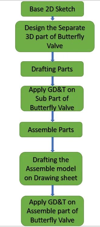
Description of tools/ Features used for designing as shown as following:-
- Creating 2D Sketch:- Creating 2D sketch for Base thickness part.
- Line :- Line is one of the most basic commands inCATIA. TO DRAW BASIC LINES AND SATIRGHRT FALT SURFACES BY USING LINE COMMNAD.
- Arc/Circle:- Use this command to create associative arcs and circle features. The type of arc you get depends on the types of constraints you combine. You can create many types of arcs by combining different types of constraints.
- Hole:- In CATIA has a command that users could create or drill standard sized holes with it. This command is called Hole and you can activate this command by clicking on it. You can create various kinds of holes that generally used in mechanical structures according to accepted standards.
- PAD &POCKET:-PAD AND POCKET, makes body or surface by EXTRUDE OR PAD THE sketch, face or closed area. Also, you can pad curves, edges, surfaces, sections, areas. and make a hole by using pocket by remiving the material in requried palce
- Drafting:- Quickly and easily create engineering drawings from 3D models using highly efficient drafting tools. The drafting software automatically creates drawing views from 3D part and assembly models, and helps you align and scale drawing views and arrange drawing sheets.
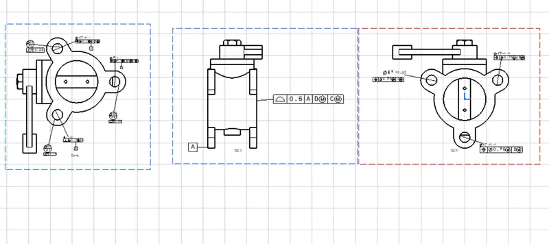
- and also used for applying the gd&t symbols...
Name of the Parts:
1. Body
2. Shaft-Stem
3. Top Flange
4. Disc Plate
5. Lever Handle
6. Nut
BODY:
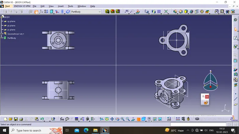
The one of the major component in butterfly valve is body that is fit between two pipe flanges. The following sets of the command used for Body designing in catia.
A.The wafer-style body is the more cost-effective of the two. It is connected to the pipes via bolt holes that run through the valve’s body. This design is simple to install and is primarily used in universal flow systems to prevent backflow. It should be noted, however, that they are not recommended for use in regulated systems.
B.Lug style butterfly valves are slightly more expensive than their counterparts, but they provide several distinct advantages. Lug butterfly valves connect to the pipe via protruding lug holes on the outside of the valve’s body. Unlike the wafer valve, the valve in this design actually helps carry the weight of the piping throughout its body.
- Sketch
- Extrude
- Counterbore
SHAFT:
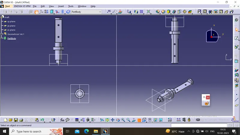
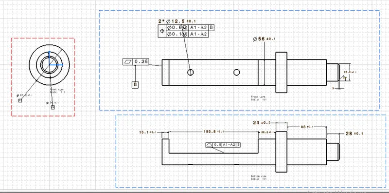
In order for the disk to be held in the proper position, the stem must extend beyond the bottom of the disk and fit into a bushing in the bottom of the valve body.The disc plate and lever are assembled to this shaft.The butterfly valve stem may appear to be a small component, but it plays an important role. The stem is what connects the disk on the inside to the handle on the outside. Without it, the valve would be unable to open or close, and what good is a valve if it cannot open or close?.
RETAINER:
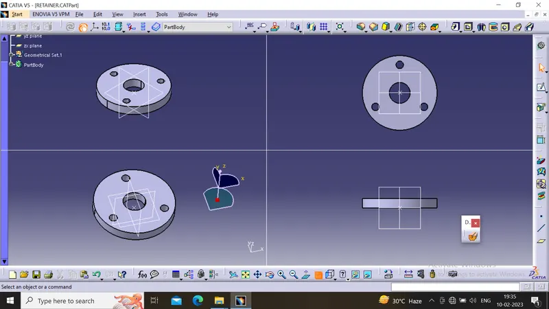
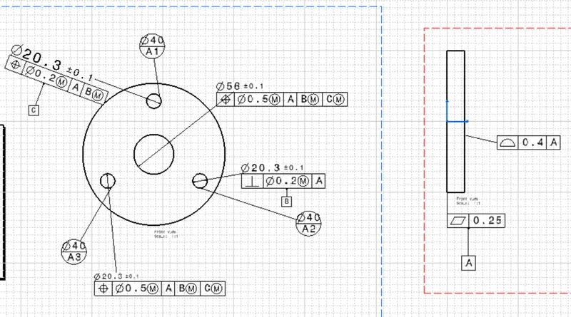
Retainer is a kind of washer fixed on the body of butterfly valve. Butterfly valves comprise a valve seat comprising a generally S-shaped cross-section and a valve seat retainer configured with appropriately shaped cooperating surfaces.
DISC PLATE:
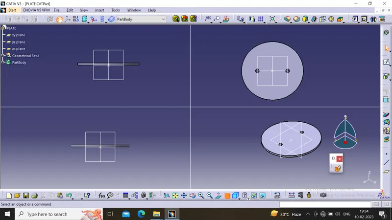
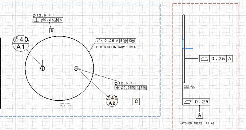
When valve is fully opened or closed the disc is rotated a quarter turn.Disc is mounted on shaft. When the valve is closed, the disc is turned so that it completely blocks off the passageway.When the valve is fully open, the disc is rotated a quarter turn so that it allows an almost unrestricted passage of the fluid.Two methods are used to secure the disk to the stem so that the disk rotates as the stem is turned. In the first method, the disk is bored through and secured to the stem with bolts or pins. The alternate method involves boring the disk as before, then shaping the upper stem bore to fit a squared or hex-shaped stem. This method allows the disk to "float" and seek its center in the seat. Uniform sealing is accomplished and external stem fasteners are eliminated. This method of assembly is advantageous in the case of covered disks and in corrosive applications.Among different parts of butterfly valve, a disk exists that has been positioned inside the body of the butterfly valve. This disk is responsible to control the flow of the fluid and works similar to the gates or balls that are placed inside the ball valves. The disk also has two types: Eccentric and Concentric. The eccentric disc has a bit more complicated design compared to the concentric. The concentric disk contains a stem that passes through the disk’s centerline. Valves with concentric disks are usually used in applications that require low pressure. The eccentric disk, in contrast, contains a stem that runs behind the center line. It is in the opposite flow direction.
The eccentric disk is among the parts of butterfly valve that has been initially designed to help prevent the contact between the seal and the disk before the butterfly valve is closed completely. This design enables the valve to have a longer lifespan.
LEVER :
Lever is mounted at an end of shaft outside the body. Hand lever is usually used in small sized Butterfly valves.Basically lever handle is used to open and close the Butterfly Valve. It provides ease of operation at the expense of speed. It can be adjusted to various positon with the help of the gearbox.
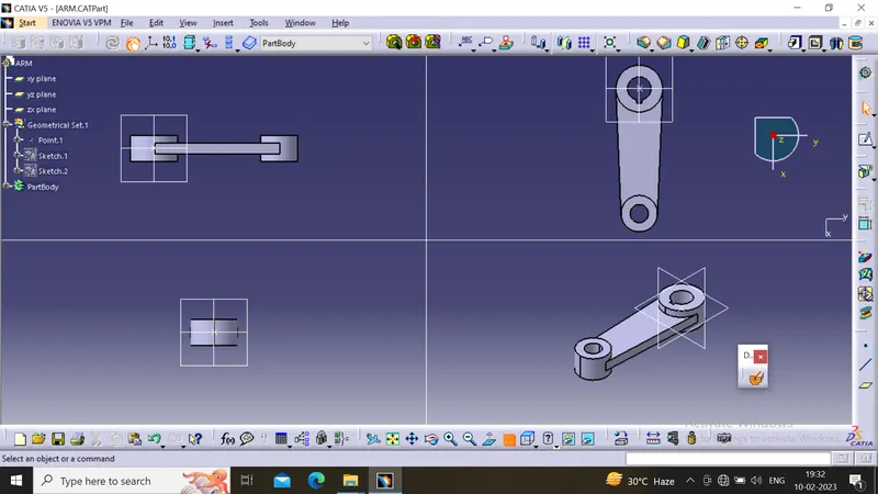
- The lever is attached at the end of the shaft/stem above the body & retainer. This lever handle is used in a small-sized butterfly valve. Using this we can regulate the flow by opening and closing the disc whenever required.
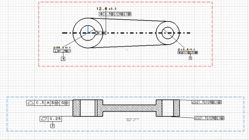
- Create two circular sketches with the appropriate diameters, and specify a suitable distance between them. Also, create a keyway slot in the bigger diameter sketch. Join these two sketches with a line tangent to both the circles.
- After creating the fully constrained sketch, first, extrude the circular regions and then extrude the mid-section with different thickness values.
- Then combine all the features using Unite command. Then create a drawing sheet of the model and apply GD&T to the drawing
NUT:
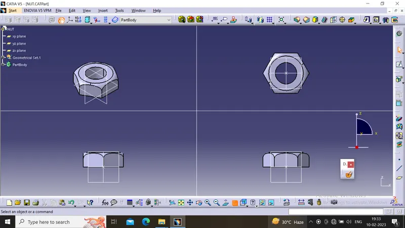
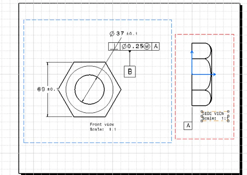
It is fixed at the top end of shaft to keep the lever and retainer on position. It is used to hold the component at the same position to add some threads inner side of the nut to make the nut stronger to hold the component.
Assembly
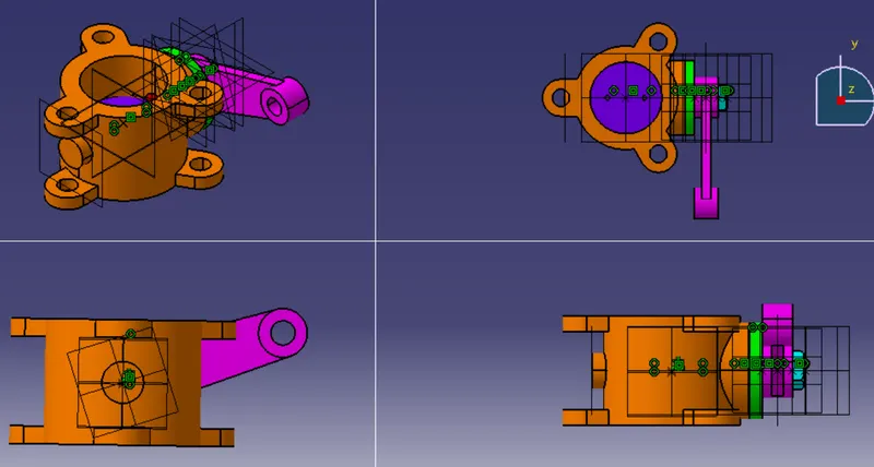
After modeling all the individual parts of the butterfly valve, all parts are assembled together in the assembly workbench of catia v5.
After the design, all the models should assemble with appropriate constraints. The assembly is created by first placing the body in position and mating other parts to it with the application of different joints provided in catia. First, the shaft and disc are joined together with the screws in place to create a sub-assembly which is then joined to the body in position. The retainer plate is then mated with the body and screws are used to fix them. After that, the lever is mated to the shaft in a position that is then fixed after the nut is mated with the shaft.
commands :- coincide ,fix,contact,manipulate...
Conclusion
The Butterfly valve is successfully created and GD&T is applied to all the different parts and the assembly of the Butterfly valve.