DOOR HANDLE
OBJECTIVES :-
- To Create the Door Handle Component from the given Class-A surface.
- To Create the tooling axis for the given Class-A Surface meeting the requirements of the draft angle.
- To Attach B side Features in the component.
- To perform the Draft analysis on the model.
Tooling Axis:
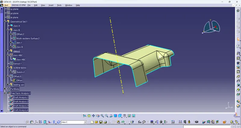
- Create a point (Coordinates) 0,0,0 mm and Create a Line - NormalTo Surface click on the point and take a surface (zx plane), give some color and make it a dashed line.
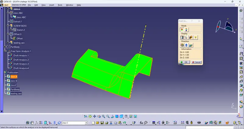
- Take a draft analysis with A surface in positive green and blue, little deviation is there.
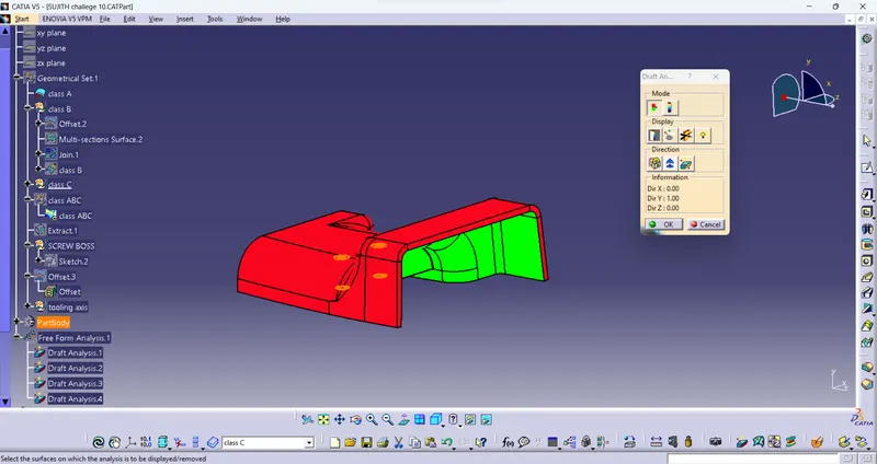
- And same thing to do in final draft analysis with final solid component, it seems a deviation green and blue that’s fine acceptable.
- And Publicate the Tooling Axis.
-
Draft Analysis
To reduce the risk of damage to parts and tool while ejecting from mold a draft angle is provided to walls which are parallel to the tooling direction. It assists with releasing the part from mold.
To perform Draft analysis in Catia, Draft analysis feature is used. For that First tooling Direction decided. Then make sure material view mode is used. After opening the window, align the compass with the tooling axis by dragging it on the axis. Then click on the surface or the body on which draft analysis is need to perform. In the bottom black colour window provide the minimum draft angle and then match the body color with this color scale. Green indicated draft angle is more than minimum draft angle. If it is blue then it is between 0 to minimum draft angle. And red denotes it is less than zero. By this way we can identify the areas with draft angle less than minimum draft angle and work on that area by changing tooling axis angle.
B SURFACE
- In the case of Class A the surface below is called core and the surface above is called cavity.
- Class A is an aesthetics surface and class B is an engineering surface.
- B surface should be inside the class A surface.
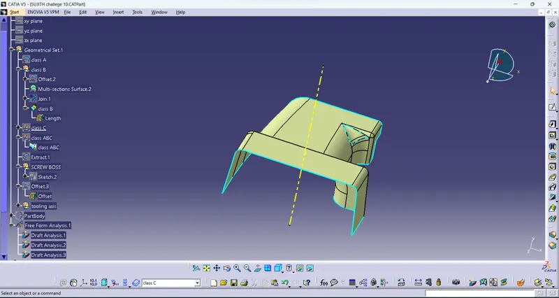
- As the class A is more complex and having multiple geometries, in this case we can directly offset the class A surface to 2.5mm thus we can obtain B surface.
- B surface is then checked for the connectivity of the surface but it will show some patches on B surface. We have to close it by extracting the required boundaries with reference to the surface and spline the uncovered area and close it by using the multi section surface, sweep and extrude method.
- All the closed patches is then then joined together by using join command and checked for the connectivity of the surface.
C SURFACE
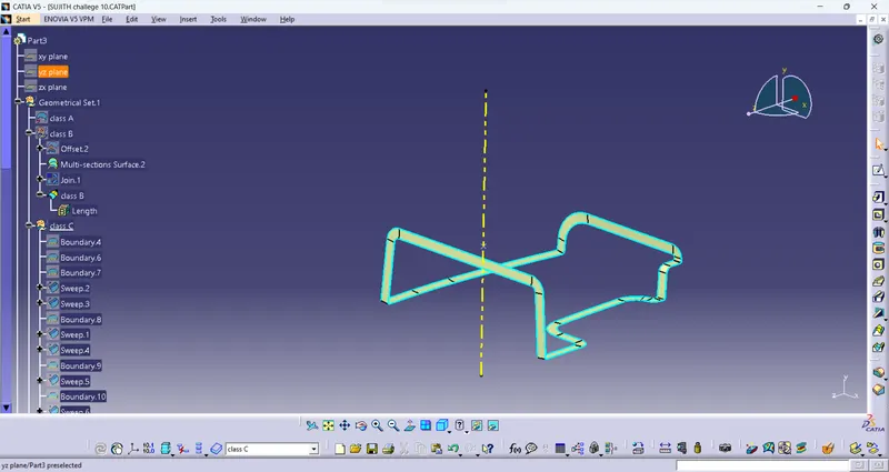
- C surface has been created from the boundary lines of class A surface and by extracting the supporting surfaces then sweep the boundary lines with reference to the extracted surfaces.
- In order to get the C surface first we have to create a boundary lines of class A surface or by using multiple extrapolated command and check for the continuity of it.
- Create a sweep with reference to the curve and the reference surface with a 90 degree angle and give the inside direction Check for the continuity of the surfaces if there is any gap go for extrapolated and trim all together now we will get the class C surface.
All the C surfaces are then trimmed to B surface and then join the trimmed surface to class A surface by join command then check it for connectivity of the surfaces we will get the final component again check whether the final body is closed by using boundary command.
Closed solid body is created by using the close surface on part workbench by selecting the final Trimmed component and do the draft analysis for the same.
Designing of Ribs
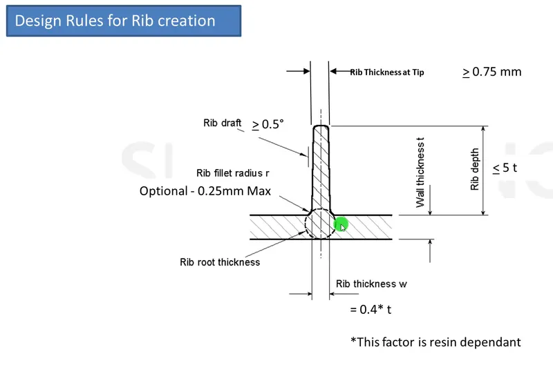
- Extract the base surface of the Rib from the solid body and draw the iso constrained base line for rib by positioned sketch method.
- Extrude the reference line by giving the proper height and then thicken it to the required size on the part work bench and give proper draft by considering pulling direction as tooling axis.
- Add it to the main body and apply proper fillet to the edges and verify all the dimensions on the rib.
- Rib root thickness can be measured with reference to the plane created on the tooling axis and choosing point as vertex on the tooling axis then intersect the body with the plane.
- Then create a circle by tri-tangential method by considering the three boundaries on the intersect then adjust the circle if it is not proper.
- Min draft: 0.5mm per side
Designing of screw boss
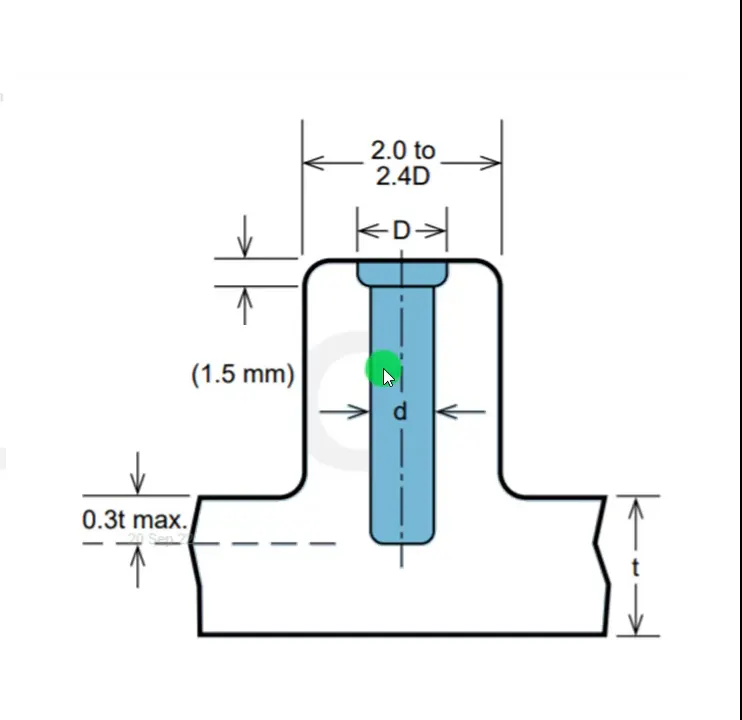
- The first step to choose the size and type of screw or fasteners used for attachment then create a cylindrical projections.
- Cylindrical projections can be created by using positioned sketch with reference to the extracted base body then pad it and assemble to the main solid body.
- Apply the draft and fillet by maintaining the guidelines for the screw boss.
- If more screw boss with same dimensions are there we can translate it and positioned them as require
- The outside diameter of boss should remain within 2.0 to 2.4 times the outside diameter of the screw or insert
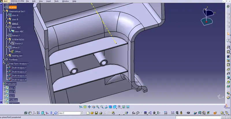
- TREE STRUCTURE :
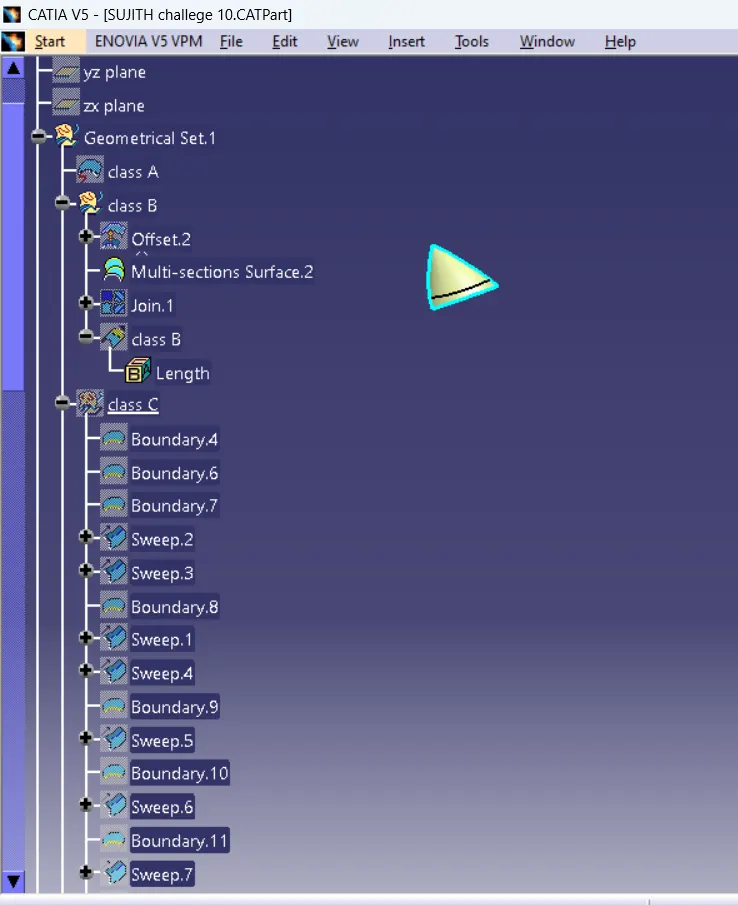
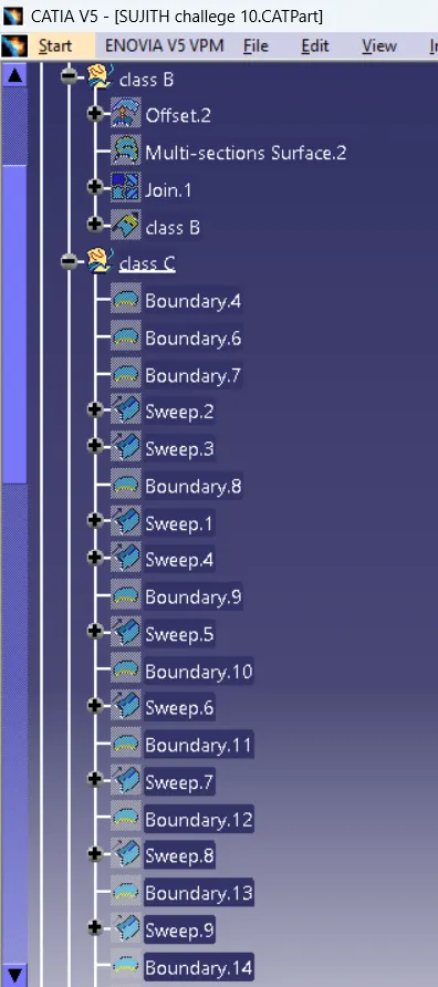
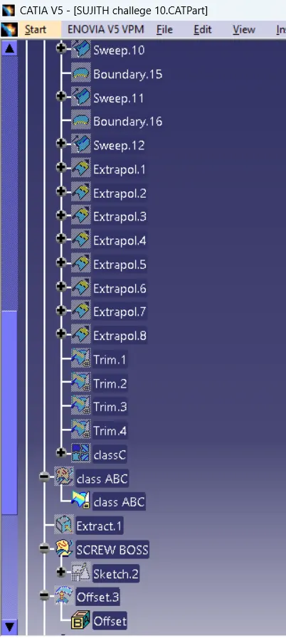
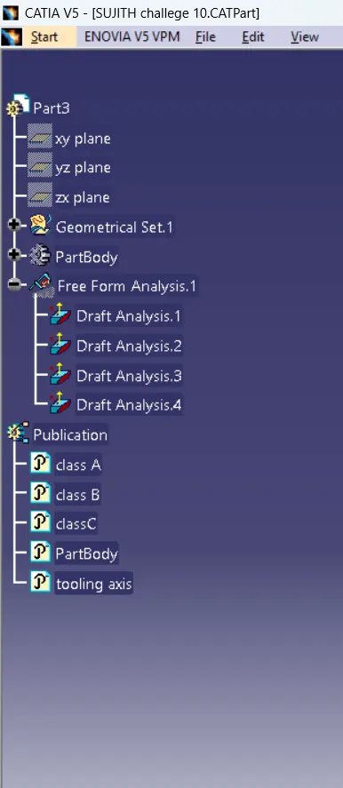
CONCLUSION:-
Class A surface of Door Handle is successfully converted into solid body And all the B side Rib and Screw Boss also created on Class B surface with the correct terminology.its passes the draft analysis also means we can conclude that its is manufacturable or Formable.