DORTRIM LOWER
Aim: To Create the Door trim lower component through the given Class-A surface.
Objectives:
• Creation of Tooling axis with appropriate draft angle.
• Creation of other surfaces (eg, B and C surfaces) for creating a solid component. • Perform Draft analysis on Class A surface and Solid model hence created.
Tooling axis creation
- The direction in which the mould open and closes is called the tooling axis direction.
- Check the connectivity of the surface and ensure there will be no gap between the surfaces and then define the tooling axis.
- While creating a tooling axis please ensure to give the tooling axis on a flat length surface or the surface which have a hole on it.
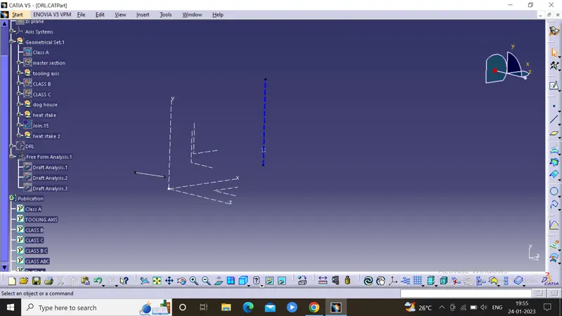
- Create a point on the middle of the base surface by using point on the surface command then create a intersection for the surface and extract the reference lines which will be helpful for creating the dummy tooling axis using the intersect method by creating a bisecting line..
- Use the line command and draw the lines which is aligned with the extracted lines and extended it to the required length.
Draft analysis
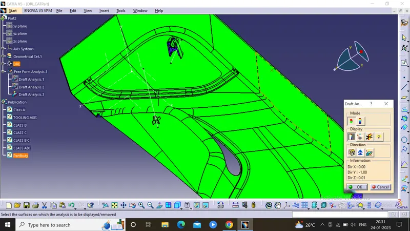
- Draft allows for the component to release from the mould, most parts or applications require a minimum of 0.5 to 1 degree draft angle and 3 dgree draft angle is widely used as per the norm.
- Change the materalistiuc mode to customize mode before moving to the draft analysis.
- Insert –analysis-feature draft analysis
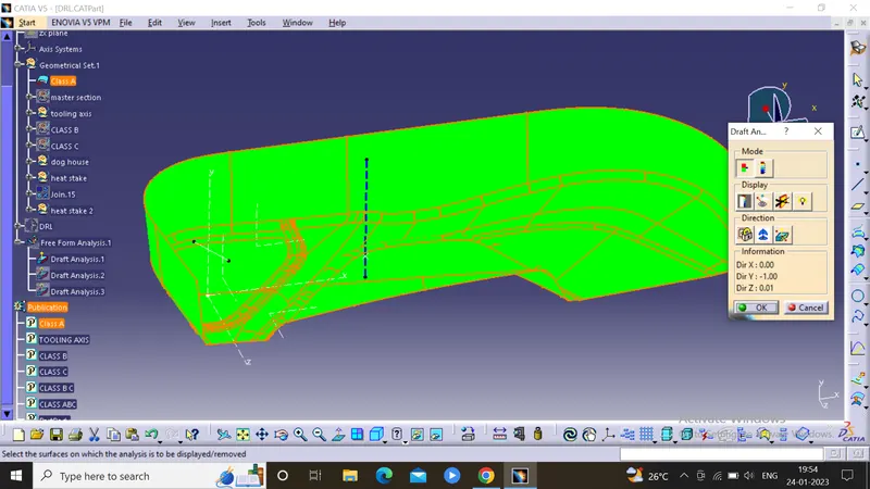
- Defining the draft direction Select draft analysis from the tool bar and click on the compass symbol and pull the compass from the right side top corner of the workbench and place it on the component where want to do the draft analysis. ‘W’ of the compass and tooling axis should be aligned on the same line.
- Once the compass is aligned with the tooling axis click on the lock symbol and drag on the surface we will get a wrong mark then select that point a table will appear it shows the draft value on the table we can adjust the draft value and analysis it for all the edges and surfaces.
- By clicking the on the surface and using the flipping tool we can assign the Flipping direction, the color of the surface change as per the flipping direction .
- Analysis under running point and move the mouse on the surface and it will show the details of the surface deg direct at each and every point of the surface.
B surface
- In the case of Class A the surface below is called core and the surface above is called cavity.
- Class A is an aesthetics surface and class B is an engineering surface.
- B surface should be inside the class A surface.
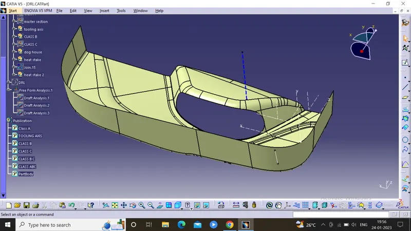
- As the class A is more complex and having multiple geometries, in this case we can directly offset the class A surface to 2.5mm thus we can obtain B surface.
- B surface is then checked for the connectivity of the surface but it will show some patches on B surface. We have to close it by extracting the required boundaries with reference to the surface and spline the uncovered area and close it by using the multi section surface, sweep and extrude method.
- All the closed patches is then then joined together by using join command and checked for the connectivity of the surface.
C surface
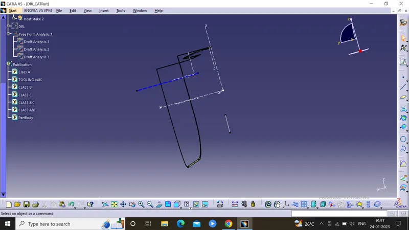
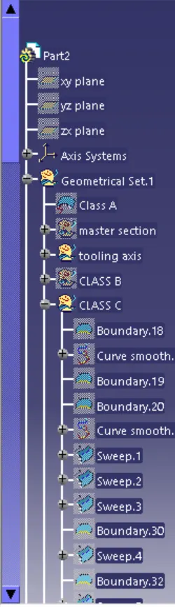
- C surface has been created from the boundary lines of class A surface and by extracting the supporting surfaces then sweep the boundary lines with reference to the extracted surfaces.
- In order to get the C surface first we have to create a boundary lines of class A surface or by using multiple extrapolated command and check for the continuity of it.
- Create a sweep with reference to the curve and the reference surface with a 90 degree angle and give the inside direction Check for the continuity of the surfaces if there is any gap go for extrapolated and trim all together now we will get the class C surface.
JOINING THE CLASS A WITH C SURFACE AND THEN TRIM IT WITH B SURFACE
- All the C surfaces are then trimmed to B surface and then join the trimmed surface to class A surface by join command then check it for connectivity of the surfaces we will get the final component again check whether the final body is closed by using boundary command.
- Closed solid body is created by using the close surface on part workbench by selecting the final Trimmed component and do the draft analysis for the same.
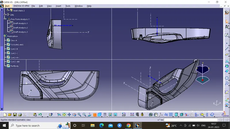
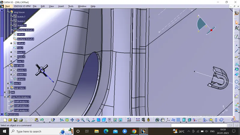
HEAT STAKES
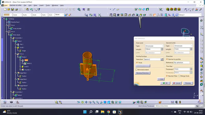
- Thermal staking is an assembly method that uses the controlled melting and reforming of a plastic stud or boss to capture or lock another plastic or metal component of an assembly in place.
- Heat stakes is used to arrest the degree of freedom of locators by 3-2-1 principle in automotive tooling design.
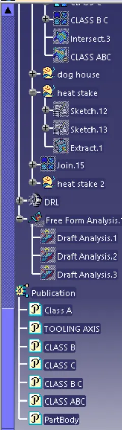
FINAL DRAFT ANALYSIS
Conclusion:
Thus the door trim lower component is created with the help of class a surface upon generating the Class B and class c surfaces and applying the proper draft analysis using catia software