Development of TFT Cluster Speedometer Software Component
Development of TFT Cluster Speedometer Software Component
TFT Cluster Speedometer
A TFT Cluster Speedometer is an advanced instrument cluster for vehicles, incorporating Thin-Film Transistor (TFT) display technology. It offers high-resolution and customizable digital interfaces to present vital driving information such as speed, fuel levels, and navigation details, enhancing the driver's experience and safety.
General functionality:
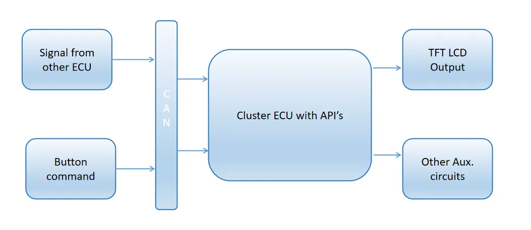
Cluster Instrument receives the signals from other ECU's via the CAN bus interface. It also receives commands from the driver via steering wheel buttons. The signals are then processed by the Cluster ECU, after which the Cluster ECU may send the vehicle information to the LCD, light the LEDs, and so forth, according to the results. Therefore, the Cluster ECU can be viewed as a carrier of the information flow.
Verification
Verification within the Verification and Validation (V&V) workflow centres on meticulous inspections, documenting requirements, and crafting both High-Level and Low-Level designs. Employing static analysis and manual checks, this phase aims to detect and rectify defects early, ensuring the product adheres to standards, is bug-free, and reliable before validation commences.
Validation:
Validation entails functional tests executed through code evaluation (integration and system acceptance) and non-functional tests(customer acceptance). This ensures not only meeting product requirements but also confirming the correct functionality of the product under specified conditions, guaranteeing its efficacy and reliability in real-world scenarios.
This project entails a fundamental implementation of a software component dedicated to displaying vehicle speed. This component is intricately integrated into the processing system of the Cluster Electronic Control Unit (ECU), a crucial element within the TFT Cluster Speedometer.
The Waterfall version of the V&V model is selected due to stable requirements and straightforward development. Its linear and sequential nature suits the following project as it has minimal changes, offering clarity, predictability, and ease in planning, making it ideal for straightforward development and maintenance.
Aim:
To execute a thorough Verification and Validation cycle ensuring precision and reliability for the Display speed software component of the TFT Cluster Speedometer.
Objectives:
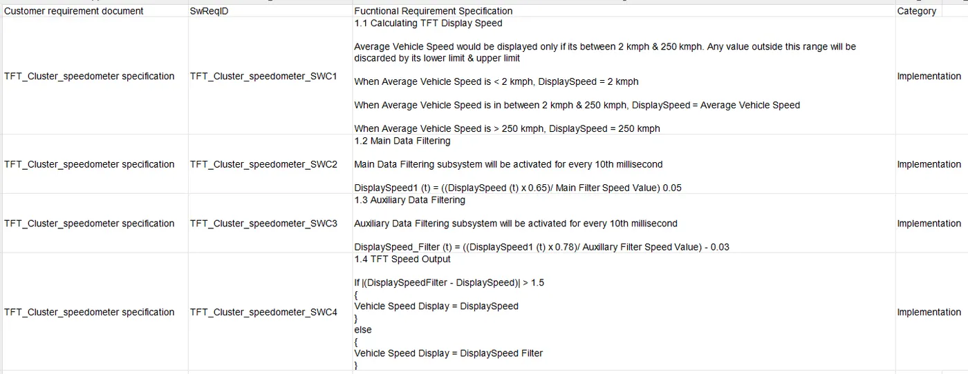
1. Requirement Documentation and analysis
a) Includes Usage of Requirement Toolbox or Manual documentation of the requirements
2. High-Level Design
a) Design of the functionality of the system by usage of blocks etc.. in accordance with the requirements
3. Building of Simulink Model
a) SLDD file creation - Simulink Data Dictionary enhances model management by centralizing data, promoting collaboration, and ensuring consistency, facilitating efficient design, simulation, and documentation in complex engineering projects.
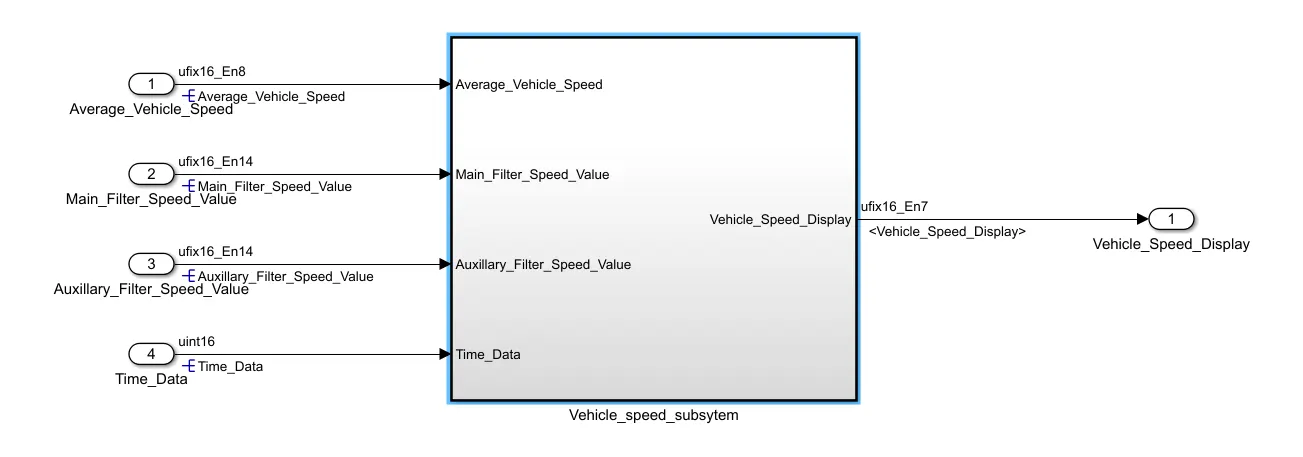
b) Development of a Model using Simulink blocks adhering to requirements.
c) Requirement tagging through a Requirement tagging tool or other means.
4. Static testing
a) Usage of Fixed Point Tool - The Fixed-Point Tool in MATLAB is essential for designing and optimizing fixed-point numerical representation, ensuring accurate and efficient implementation of algorithms for embedded systems and hardware.
Note: While the Fixed-Point Tool simplifies fixed-point arithmetic in MATLAB, thorough checks and adjustments are crucial to guarantee the correct functionality of data types.
b) JMAAB guideline check (As per requirement) using Model Advisor and Static analysis.
c) Usage of Design Verifier - Design Error Detection to detect any dead logic in the model and produce the report for the same.
5. Code Generation
a) Choose the embedded Coder(ert.tlc) in the Code Generation con-fig parameters and ensure the appropriate toolchain is installed in the system.
b) Build the code
6. System Testing and Acceptance testing
a) Development of Functional test cases
b) Development of MIL Harness and analyzing model coverage.
c) Development of SIL Harness and comparison of the output with the output from MIL Harness
d) Test Generation in Design Verifier - Automatic analysis of Dead logic and production of test cases for coverage analysis.
e) Producing relevant reports for the same.
7. As a part of the project objective we repeat step 6 using the Simulink Test Manager
a) Simulink Test Manager - Simulink Test Manager streamlines the testing process by managing test cases, executing simulations, and analyzing results. It ensures systematic validation and verification of Simulink models, promoting robust and reliable designs.
b) Usage of Baseline Test - Baseline tests compare the outputs from a simulation against the expected outputs.
c) Usage of Back to Back Test - Facilitates parallel run and comparison among the model subsystems
d) Producing the relevant reports.
Implementation of Objectives:
1. Requirement Documentation and analysis
2. High-Level Design
3. Building of Simulink Model
a) SLDD file creation
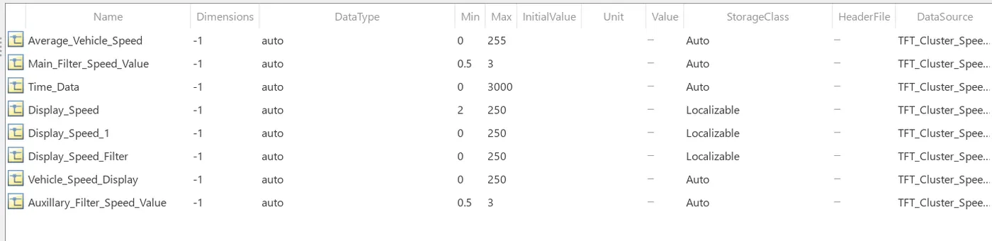
Note: Choose appropriate storage classes.
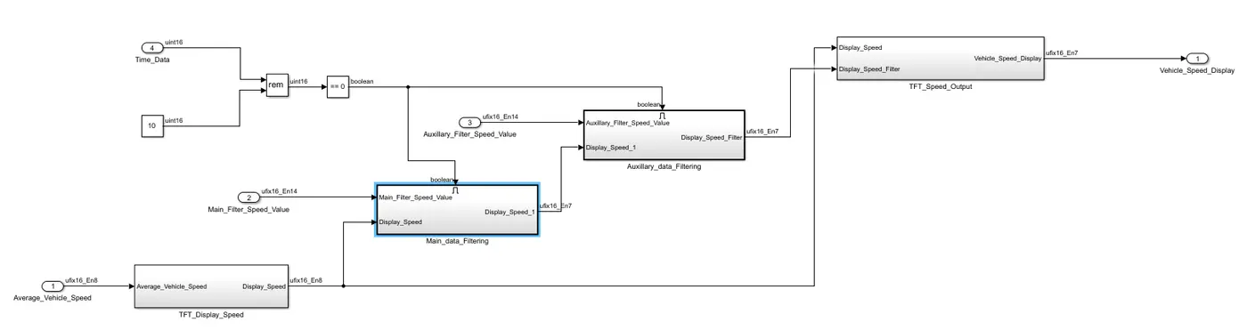
b)Model Creation
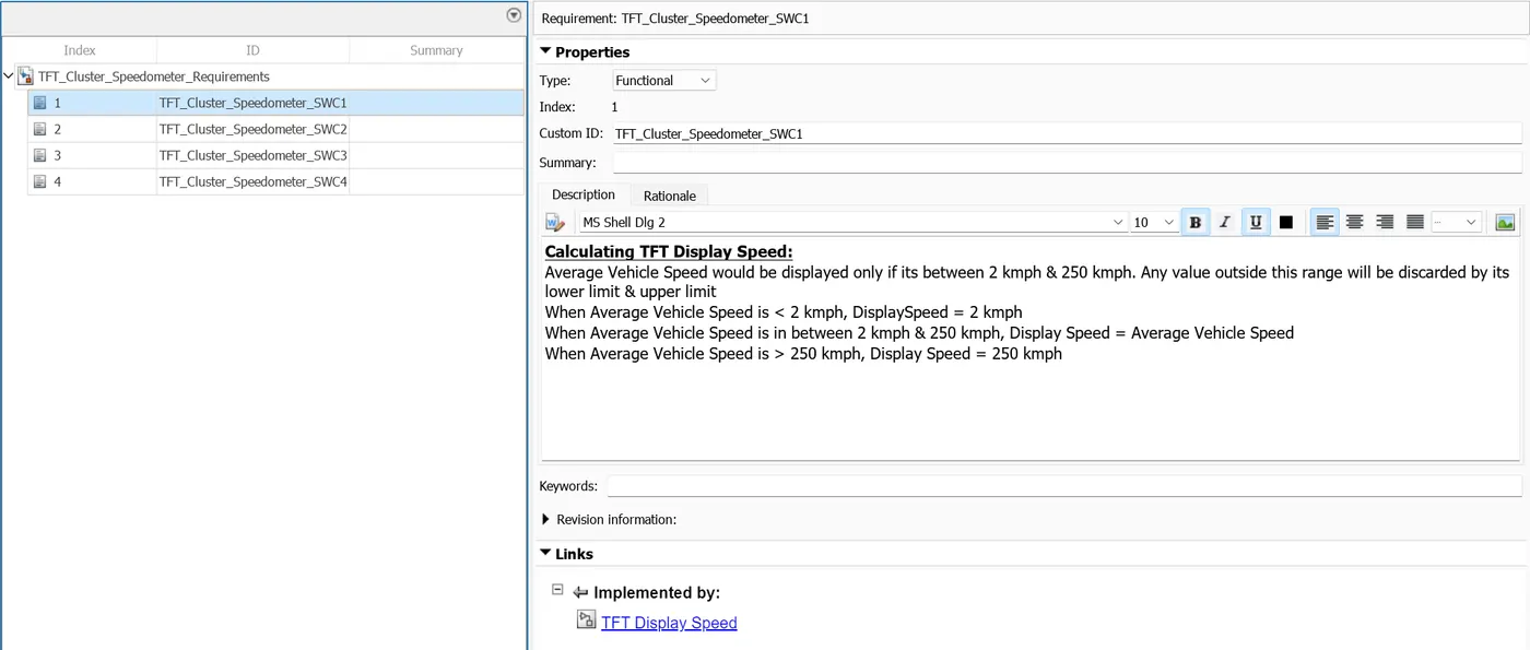
c)Requirement Tagging
Apps --> Requirement editor
4. Static testing
a) Fixed Point Tool
b) JMAAB guideline check -- Find the report and Static analysis
c) Design error Detection -- Find the report below
5. Code Generation
Please find the attached in the Zip file.
6. System Testing and Acceptance testing
a) Functional test cases.
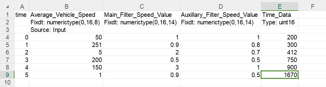
Note: The datatype specification is important here because by default the values are of double datatype. There is a workaround i.e. use a Data type conversion block with the setting of data type as "inherit via backpropagation".
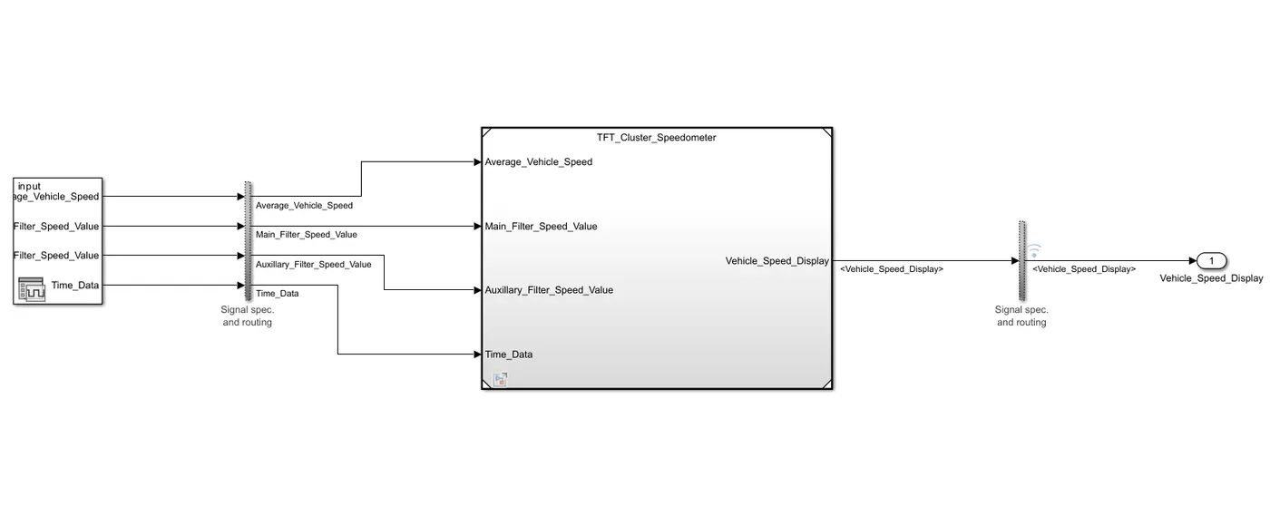
b)MIL Harness and SIL Harness with model coverage reports:
MIL Harness
SIL Harness
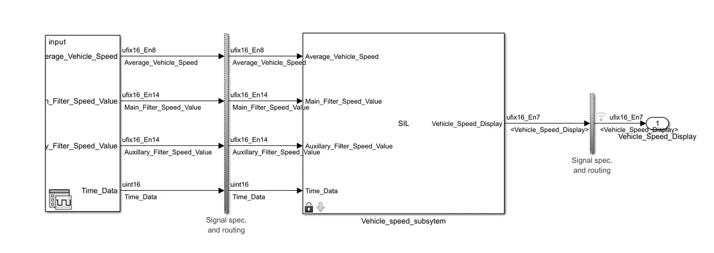
Note: Usage of the signal editor as it default provides an option to specify the data type of the input.
The reports of the Coverage of SIL and MIL harness are attached as a zip file.
Follow the following steps for a better understanding of Signal Editor:
Step 1:
If there is no relevant mat file click on the Launch signal editor (circled)
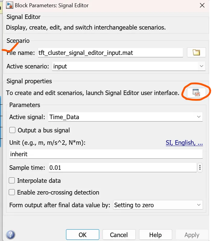
Step 2:
Click on Open and choose Import.
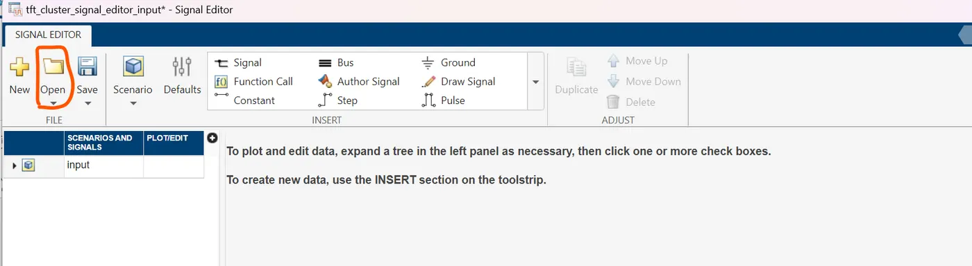
Step 3:
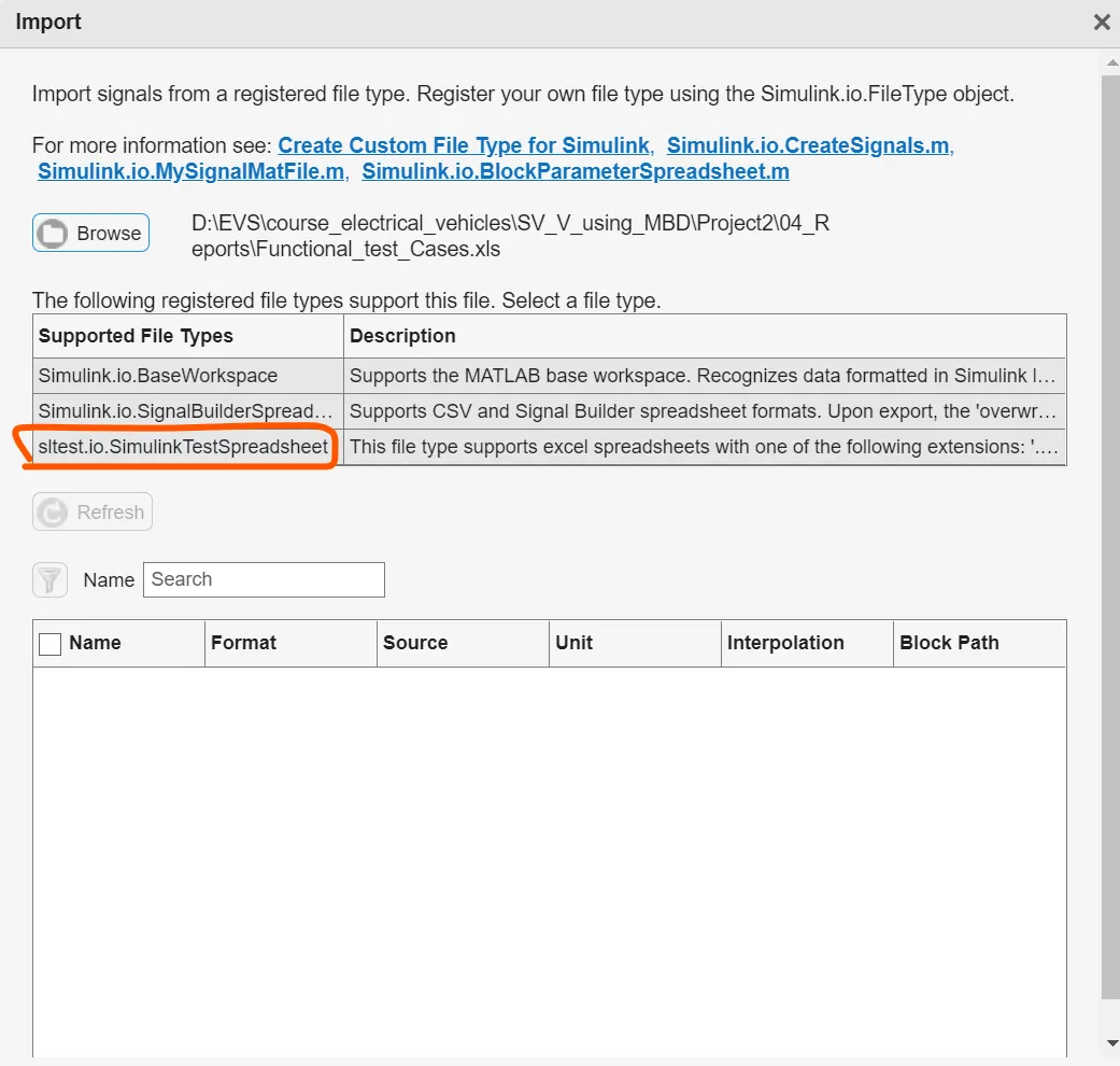
Use the browse option and select the xls file which has the datatypes specified (refer to the image in the section functional test case above)
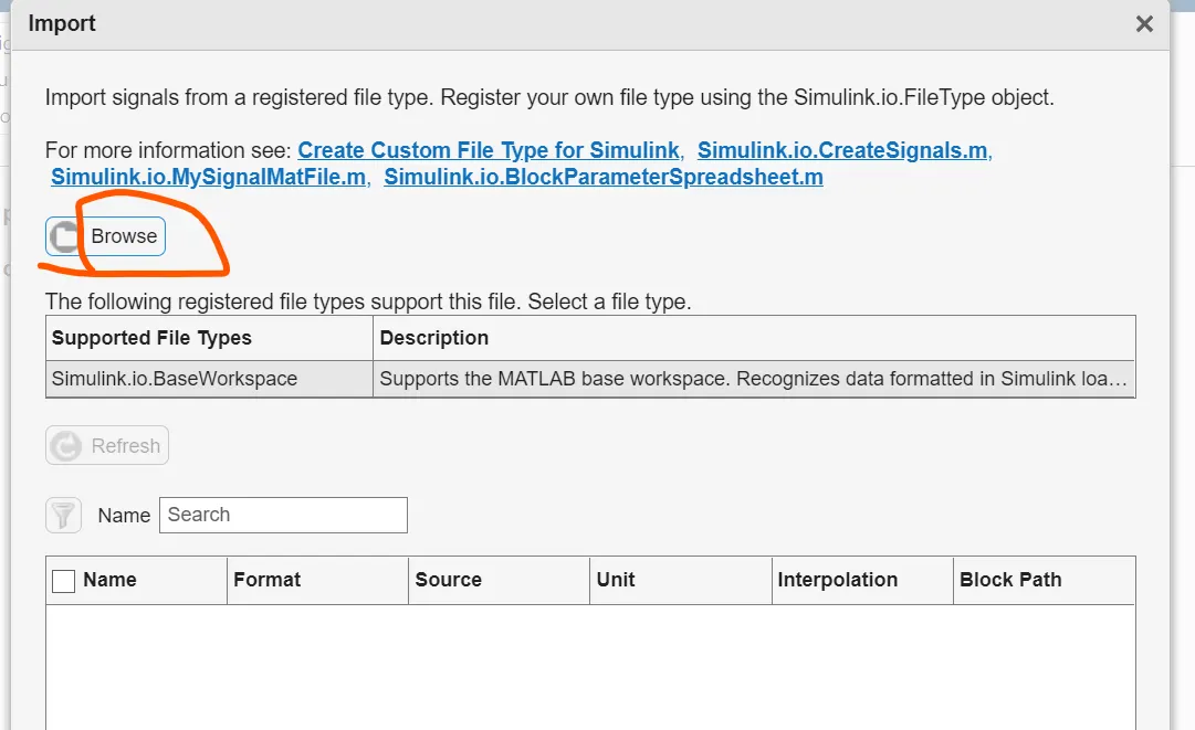
Step 4:
Explore the 3 options; the 3rd option suits files of spreadsheet type. and click on the desired option
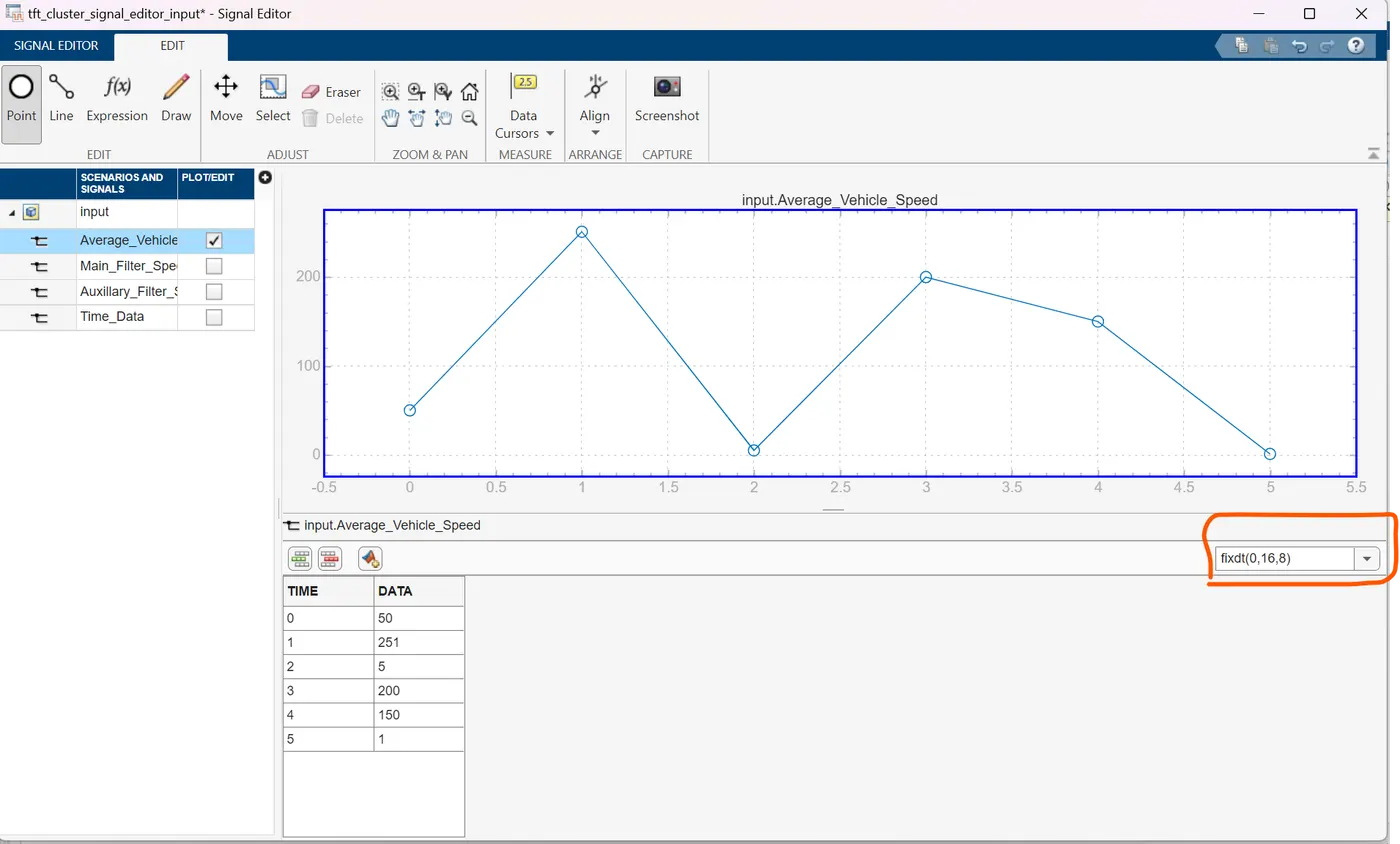
Step 5:
Notice the data type circled and as per our requirement
Step 6:
After step 5 click Ctrl+S (save) the data gets saved as a .mat file
Select the sample time that has been set for the model for each active signal.
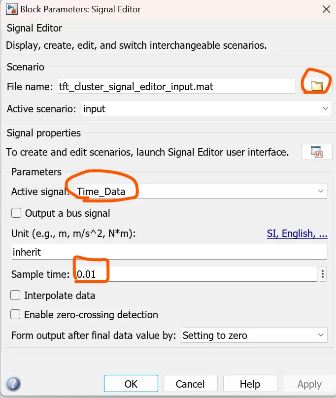
and that wraps up the usage of the signal editor.
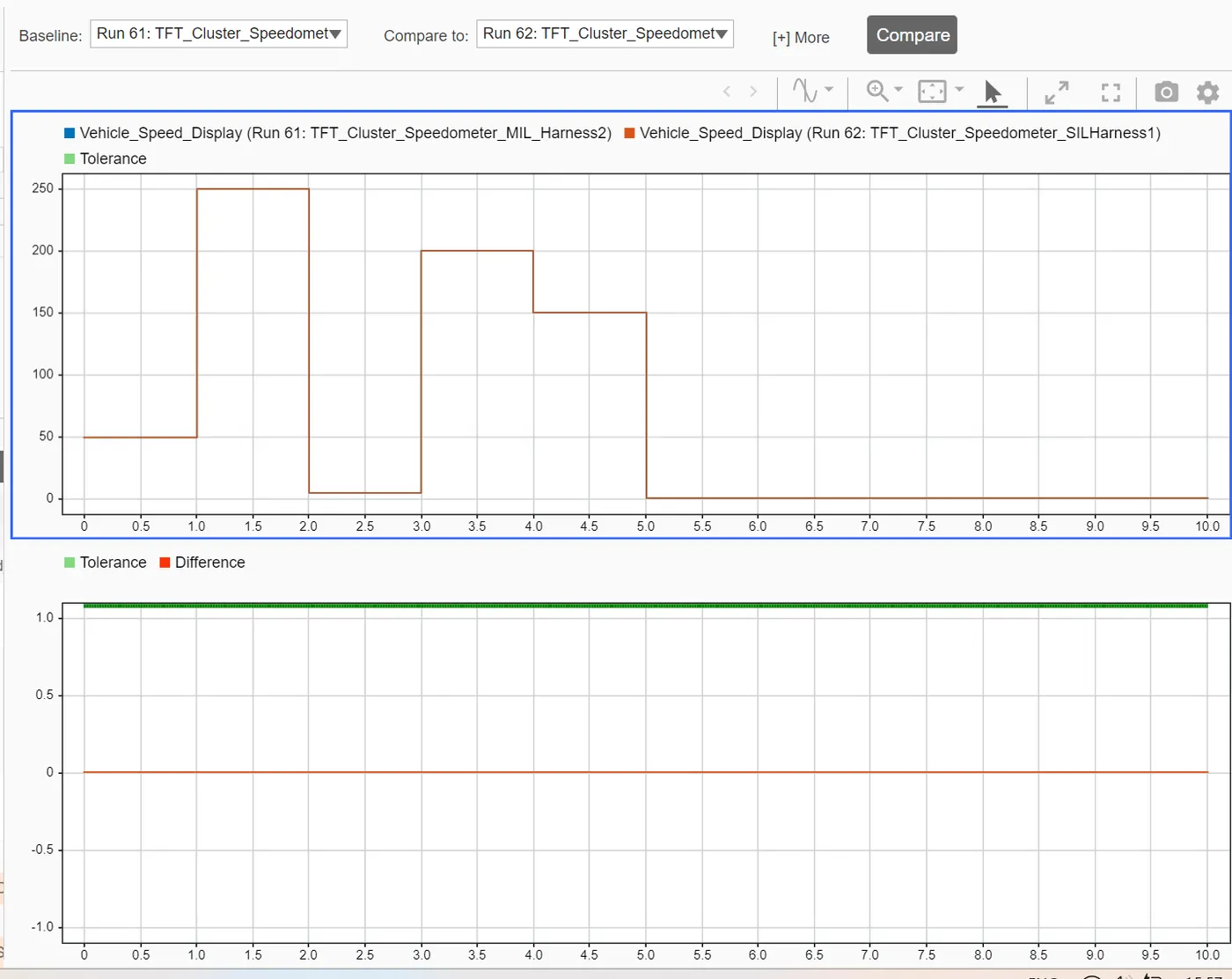
Comparison of Output of MIL and SIL Harness for the functional test case inputs.
d) Test generation in Design Verifier - Please find the report attached.
7. Repeatation of Step 6 In the Simulink test manager.
a) Baseline testing -- Find the report attached .
b) Back to Backtesting -- Find the report attached.
Note: Due to the unavailability of the Ployspace analysis tool the reports for the same cannot be produced here. The process of doing so is detailed in Challenge 9.
Result :
Therefore all the objectives were met in the above process and the results were analysed.
Contents of the ZIP file:
TFT_Cluster_Speedometer.slx
TFT_Cluster_Speedometer_SLDD
TFT_Cluster_Speedometer_code.zip
TFT_Cluster_Speedometer_Requirements.slreqx
1.TFT_Cluster_Speedometer_Requirements
2.TFT_Cluster_Speedometer_JMAAB_Report
3.TFT_Cluster_Speedometer_Design_error_report
4.TFT_Cluster_Speedometer_MIL_coverage_report
5.TFT_Cluster_Speedometer_SIL_coverage_report
6.TFT_Cluster_Speedometer_test_generation_report
7.TFT_Cluster_Speedometer_B2B_report_1
8.TFT_Cluster_Speedometer_Baseline_report
9.Functional_test_Cases.xls
10.tft_b2b_input_2.xls