Adaptive Cruise Control
1. General Overview:
Given as above Adaptive cruise control is the major aspect of the Advanced Driver Assistance system.
2. Objective:
To understand the requirements and build a Simulink model that mimics an Adaptive cruise control.
3. Requirement Analysis:
Please find the attached word to see the requirements.
4. Designing of Base Simulink Model:
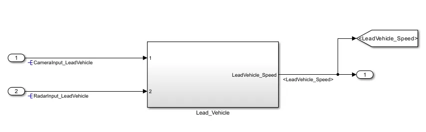
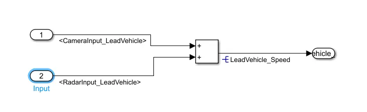
Requirement 1:- Lead Vehicle:
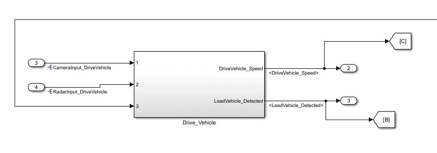
Requirement 2:- Drive Vehicle:
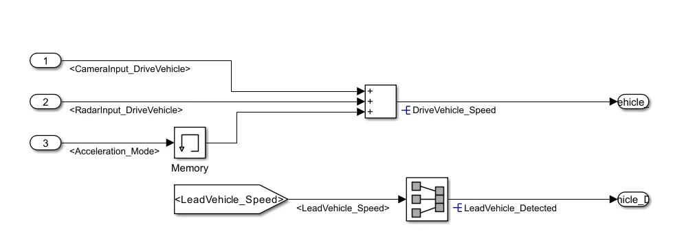
It is worth noticing the usage of Memory block...
The output of the Stateflow model drives the output of the Drive Vehicle subsystem and the output of the Drive vehicle subsystem acts as an input to the stateflow model thus forming an algebraic loop.
The Simulink algebraic solver usually solves an algebraic loop but when the loop includes a stateflow model it cannot solve the same, Hence we add a memory block which creates a delayed output.
The usage of too many memory blocks must be avoided as it increases the simulation time.
Requirement 3:- Statemodel of Adaptive Cruise Control Algorithm
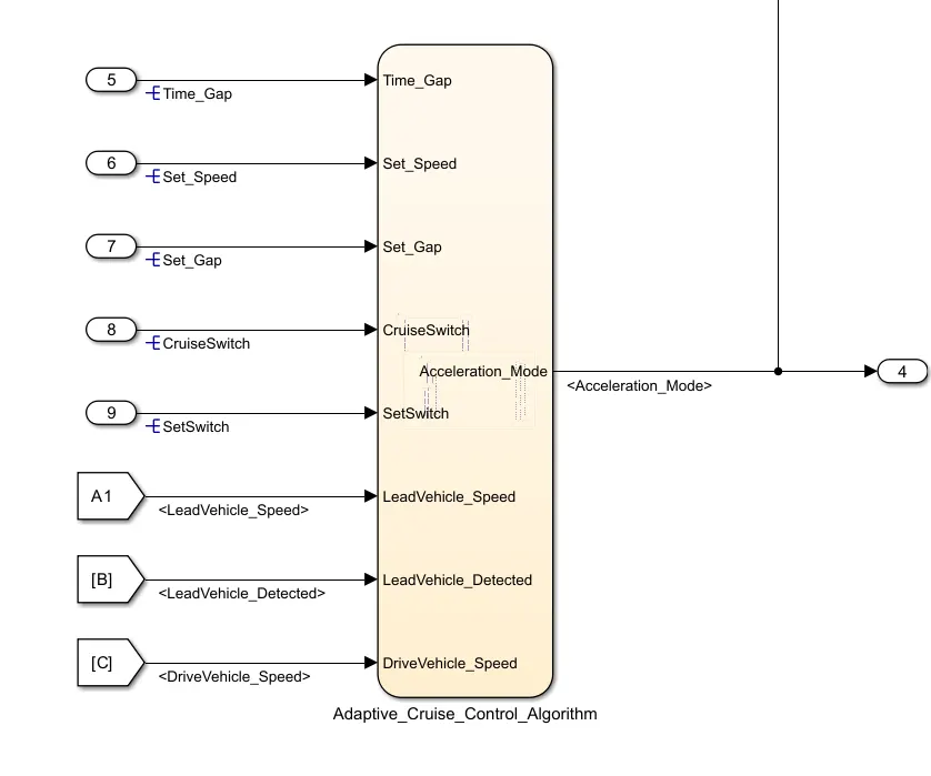

It is worth noticing that the stateflow model property Action Language is changed to C to adhere to MAB guidelines.
(Right-click after opening the chart and navigate to properties to find the option of Action Language).
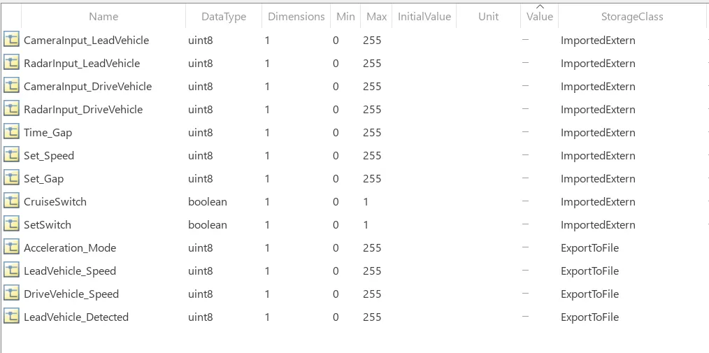
5. Building the SLDD file:
6. Requirement Tracking and Traceability
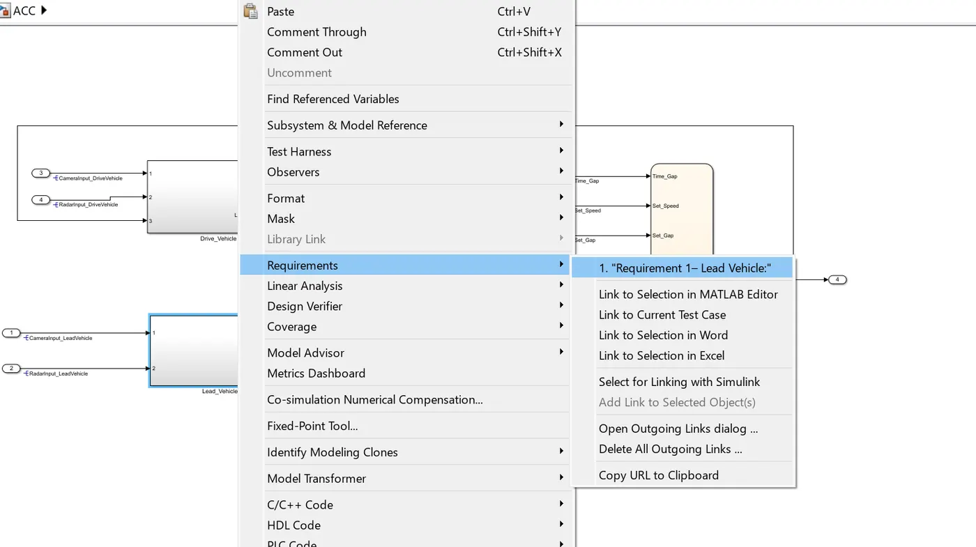
Requirement tagging is essential for easy understanding of the requirement about any subsystem or any block by attaching the reference document to them as follows.
- Open the Word / Excel or the supported format and select the text that is to be tagged for the Subsystem/block/part of the model or the whole model.
- Now go to Model, Select the Subsystem/block/part of the model or the whole model --> Right click and find the requirement option ---> Choose from the drop-down the appropriate format and click okay.
7. Configuration settings:
Use Ctrl+E to navigate to the Configuration parameters of the Simulink Model.
Set the required solver settings of step size 0.01 and system target file as ert.tlc (embedded coder) in code generation.
8. Model Advisor Check:
Check for static build errors by pressing Ctrl+D before performing the model advisor check.
Run the model advisor check present in the modelling tab by choosing to check the required checks needed. Make the necessary changes to adhere to the selected guidelines.
Please find the attached Model Advisor check report in .html format. (only MAB guidelines were checked in this case)
9. Output:
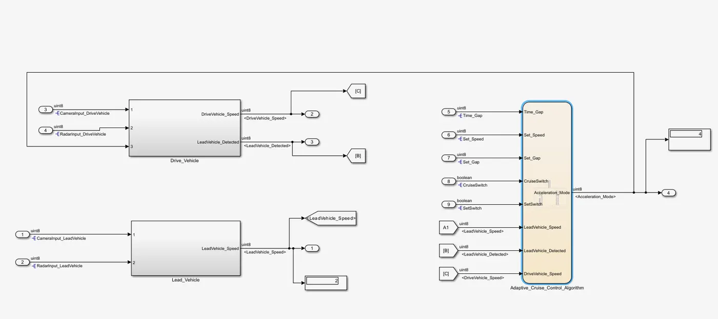
A single scenario was simulated and the output is as follows.
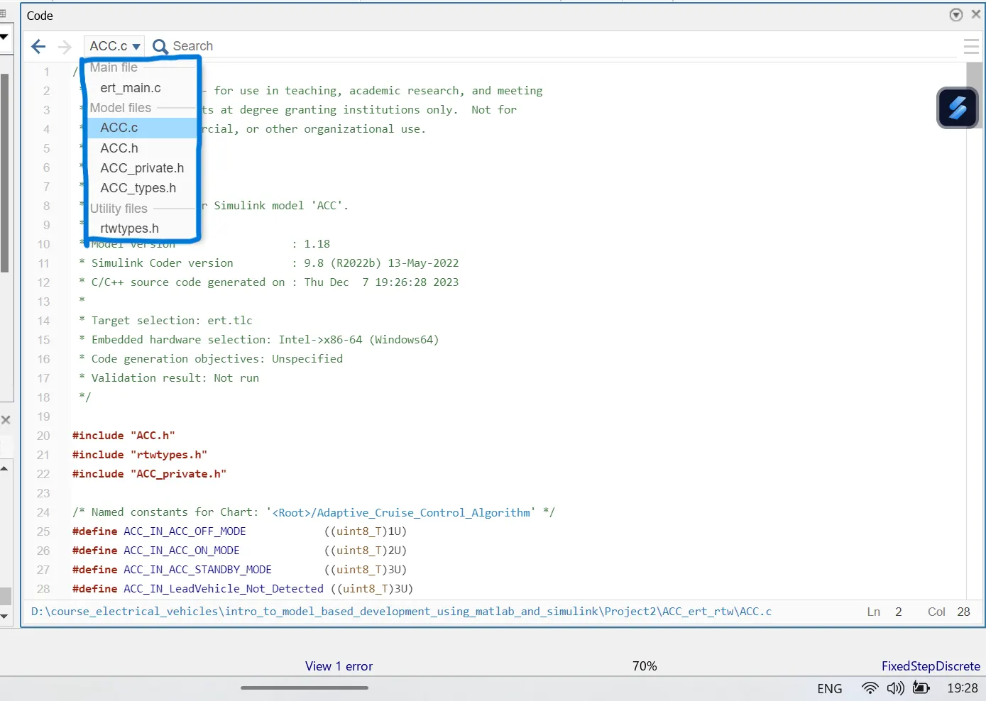
10. Code Generation:
After the checks are complete Build the Code.
Please find the attached Zip folder.
The following files were generated.
11. Result:
The Simulink model was made as per the requirements and the simulation was successful thus mimicking the behaviour of ACC to a near extent.