DEVELOPMENT OF DOOR TRIM PANEL
OBJECTIVE
To design a lower door trim panel of automotive using CATIA V5.
Introduction
To create the Door Trim Lower's Plastic Component using the Class A Surface that is provided. Desired Thickness of the Plastic Component is 2.5mm with 3 degrees as the Draft Angle.
Firstly, we have to create the required Tooling-Axis for the given Class A Surface while meeting the requirements of the necessary Draft Angle & then perform the Draft-Analysis Operation on the Class A Surface itself.
After that, we have to create the required Class B & Class C Surfaces using which we have to create the Final Plastic Component and perform Draft Analysis on it as well.
software used:
CATIA V5-R20
THEORY
Door panels serve as an interface between the interior of the car and the inner workings of the door, and between vehicle occupants and the door door panels also kown as door cards.Modern cars often have door cards that are constructed of plastic and incorporate other decorative elements.injecton molding is the most commonly used method.the Other features like vehicle's aesthetic, functionality, and ergonomics are usually included in the door panel
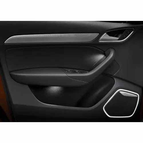
fig:A type of door panel
PROCEDURE
The class A surface of the door panel will be given by the styling team .In industry there is a separate team is allocated for the styling department.
so the class A is the first input given to the plastic designer
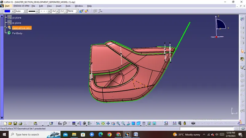
fig: door panel class A front side
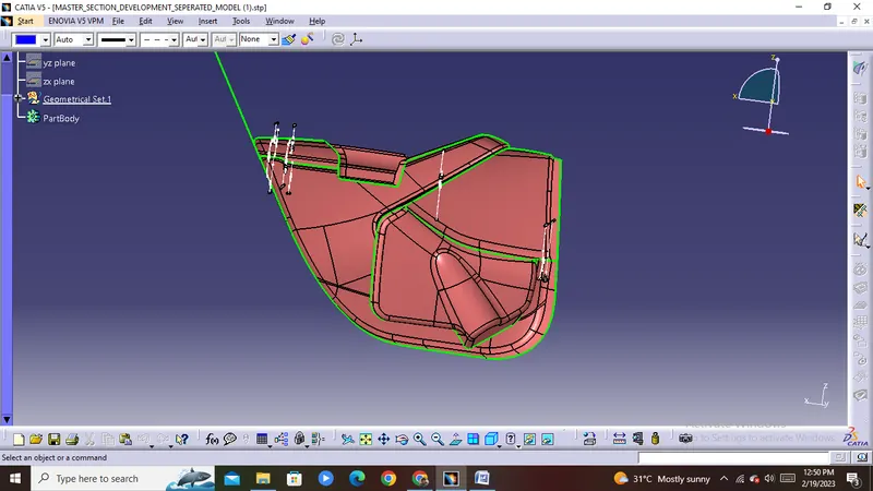
fig:Door panel c;ass A back side
CREATION OF ASSEMBLY:
the class A surface consist of the following parts
- Door Arm Rest
- Lower Substrate
- Map Pocket
- Bottle Holder
Open the assembly design copy each part into the assembly design parts and edit them there other wise devide and edit each part in separe sections and assemble them finally
1.Door arm rest
sep1:tooling axis
create a tooling axis for the class A surface of the door arm rest by creating a point on the surface and creating a line along with the direction in the desired way
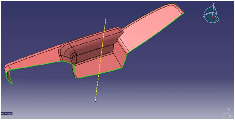
fig:tooling axis of door arm rest
stpe2:draft analysis
do the draft analysis for the class class A surface withe help of tooling axis
--change the material conditon to materialstic mode
--go to insert ,click on analysis ,select feature draft analysis
--drag the compass on to the tooling axis
--adjust the compass and click on the lock command
--after that select the surface
--the draft angle may be maintained at 3°
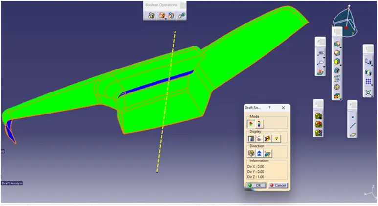
Fig :draft analysis on class A surface
step3:Creation of classB surface
--class B surface can be created by off setting the class A surface with a distance of 2.5mm with the help of offset command.
--after offseting there will be some gap will be come that can be completed by using spline,boundary, multisection and sweep comands
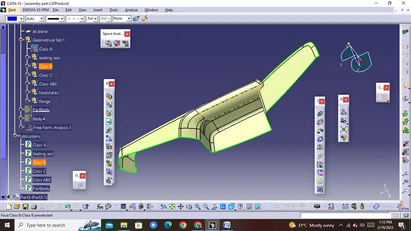
FIG:class B surface
Step4:draft analysis on class B
the draft analysis can be done by following the above mentioned instructions
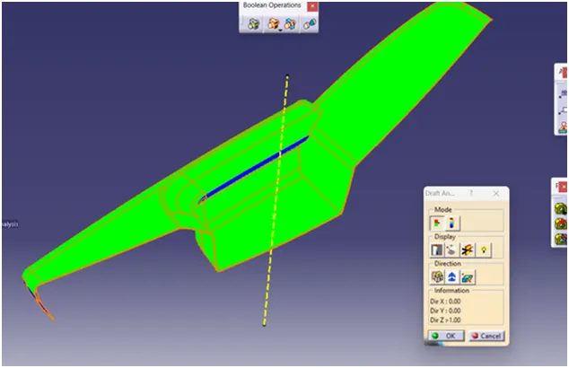
stpe5:creation class C
--by using the extract command extract ,extract the boundaries of the class A surface.
--with the help of sweep command add the material to the boundary that are extracted
--Due to surface irregularities, it was not possible to create a single sweep. Hence, several sweeps and multisection were created, and finally, they joined together to create a class C surface
--with the helpof join command join all the sweeped material
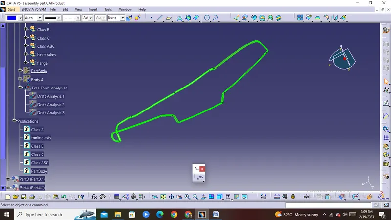
step6:CREATION OF CLOSED SURFACE
--join the class A and class c surface and named it as AC
--join the AC surface to the B surface
-- by joining them the closed surface will get
--The join of Class A and Class C surface is trimmed with class B surface to create a closed surface. While performing trim operation errors were coming as a proper intersection was not happening. Hence with the help of extrapolating command class B surface was extrapolated and finally trimmed.
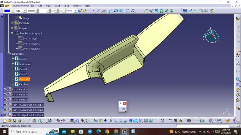
fig:class ABC surface
-draft analysis for the class ABC
after creating ABC surfface make a Draft analysis with the help of above instructions along the tooling axis
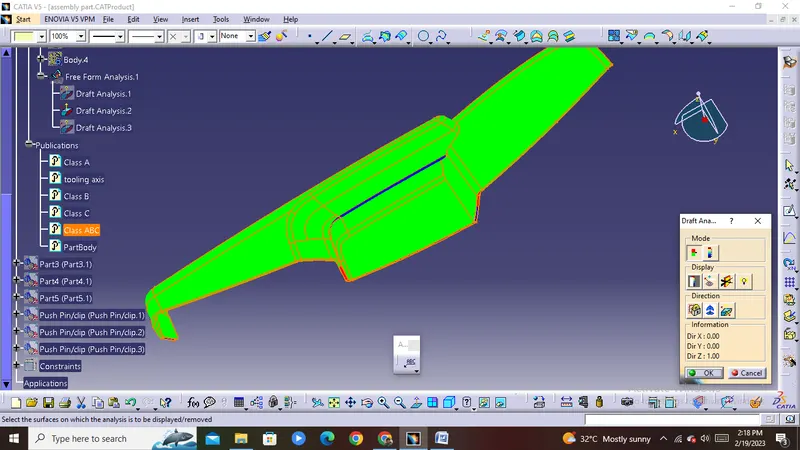
fig:draft analysis on class ABC
step7:creation of solid body
--after creating the ABC surface with the help of closed surface command create an an closed solid part body
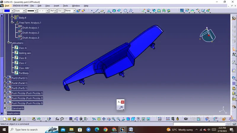
fig:closed surface of door arm rest
after creating solid body perform the draft analysis on the body
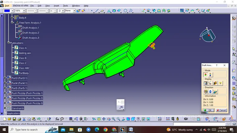
2 LOWER SUBSTRATE
Class A surface of lower substrate
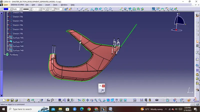
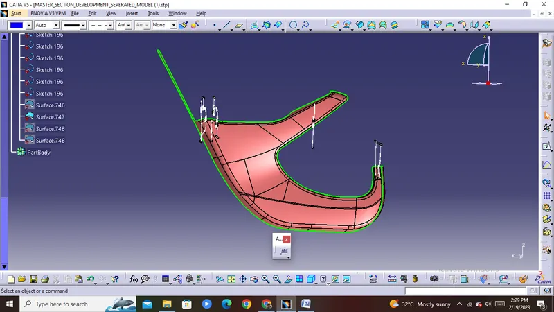
CREATION OF TOOLING AXIS:
The line has been created using the line command. The point-direction option is used to create the main tooling axis in the Y-direction.
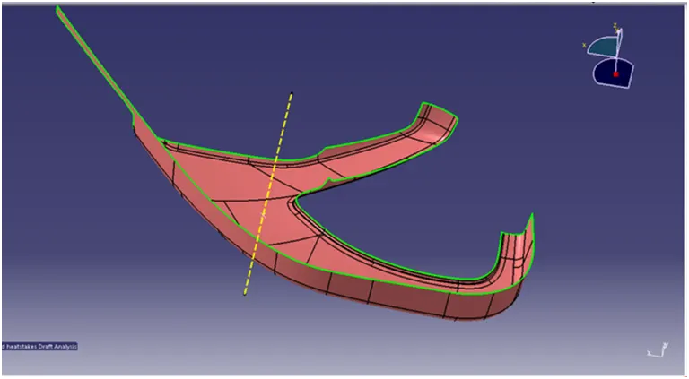
fig:tooling axis of lower substrate
Draft analysis of class A
do the draft analysis for the class class A surface withe help of tooling axis
--change the material conditon to materialstic mode
--go to insert ,click on analysis ,select feature draft analysis
--drag the compass on to the tooling axis
--adjust the compass and click on the lock command
--after that select the surface
--the draft angle may be maintained at 3°
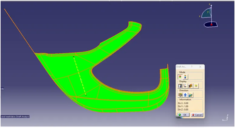
fig:draft analysis on class A
CREATION OF CLAS-B SURFACE:
Class B surface has been created by offsetting of class A surface. Offsetting has been done using the offset command. Class A surface is offset with a 2.5 mm distance.
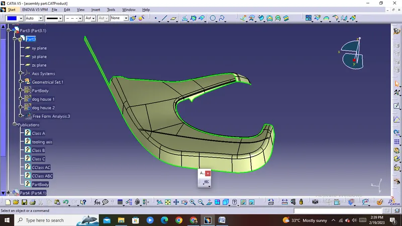
creation of class C surface
by using the extract command extract ,extract the boundaries of the class A surface.
--with the help of sweep command add the material to the boundary that are extracted
--Due to surface irregularities, it was not possible to create a single sweep. Hence, several sweeps and multisection were created, and finally, they joined together to create a class C surface
--with the helpof join command join all the sweeped material
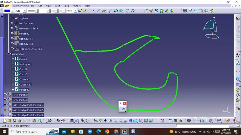
creation of closed surface
join the class A and class c surface and named it as AC
--join the AC surface to the B surface
-- by joining them the closed surface will get
--The join of Class A and Class C surface is trimmed with class B surface to create a closed surface. While performing trim operation errors were coming as a proper intersection was not happening. Hence with the help of extrapolating command class B surface was extrapolated and finally trimmed.
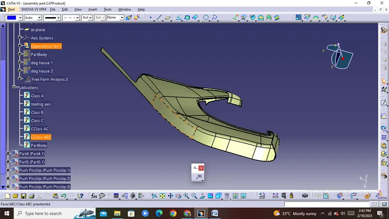
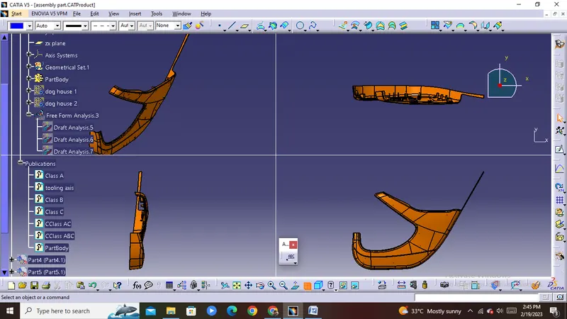
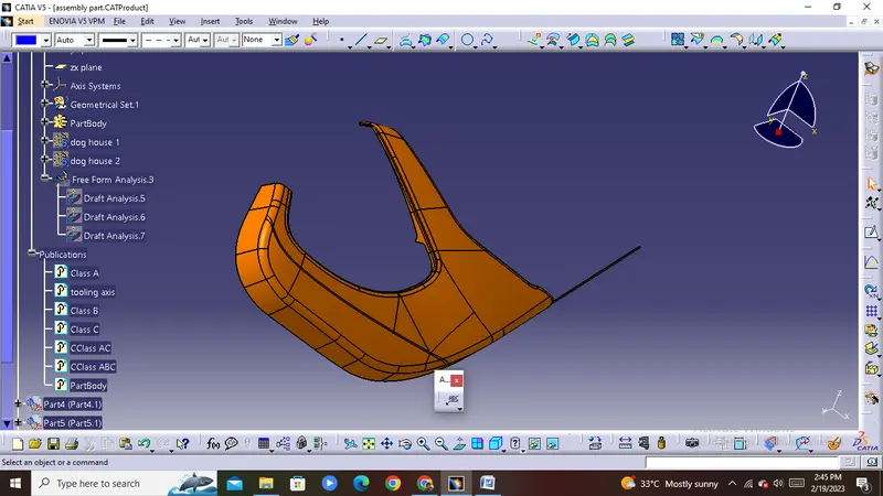
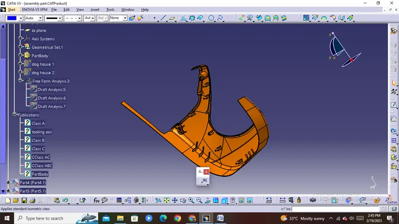
Draft analysis on closed surface
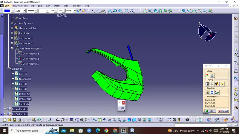
creation of closed sloid body
after creating the ABC surface with the help of closed surface command create an an closed solid part body
3.MAP POCKET
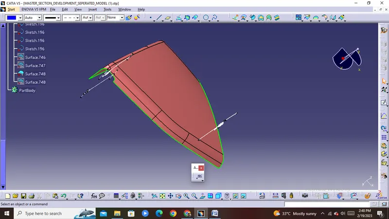
class A surface of map pocket
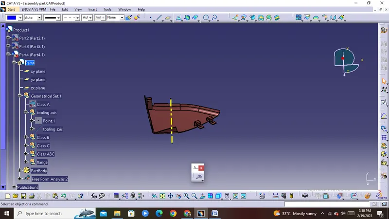
CREATION OF TOOLING AXIS:
The line has been created using the line command. The point-direction option is used to create the main tooling axis in the Y-direction.
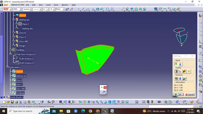
DRAFT ANANLYSIS ON CLASS-A:
- Change View Mode Customization to Material mode.
- Go to INSERT--->ANALYSIS--->FEATURE DRAFT ANALYSIS and move the compass to the moving Axis.
- Change the range to 3°. Apply the settings as shown in below image.
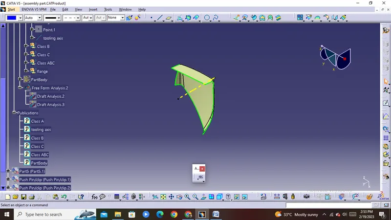
CREATION OF CLAS-B SURFACE:
--class B surface can be created by off setting the class A surface with a distance of 2.5mm with the help of offset command.
--after offseting there will be some gap will be come that can be completed by using spline,boundary, multisection and sweep comands
CREATION OF CLAS-C SURFACE:
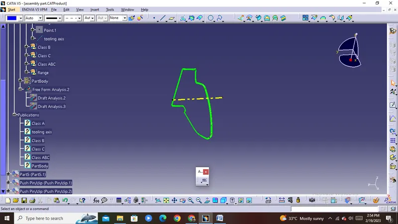
by using the extract command extract ,extract the boundaries of the class A surface.
--with the help of sweep command add the material to the boundary that are extracted
--Due to surface irregularities, it was not possible to create a single sweep. Hence, several sweeps and multisection were created, and finally, they joined together to create a class C surface
--with the helpof join command join all the sweeped material
CREATION OF CLOSED SURFACE:
join the class A and class c surface and named it as AC
--join the AC surface to the B surface
-- by joining them the closed surface will get
--The join of Class A and Class C surface is trimmed with class B surface to create a closed surface. While performing trim operation errors were coming as a proper intersection was not happening. Hence with the help of extrapolating command class B surface was extrapolated and finally trimmed.
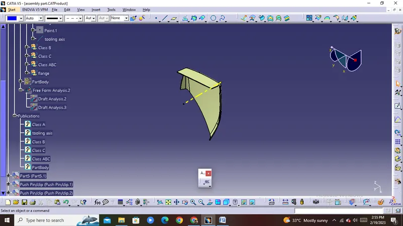
Draft analysis on ABC
perform the draft analysis on class ABC by using the above instruction
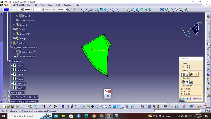
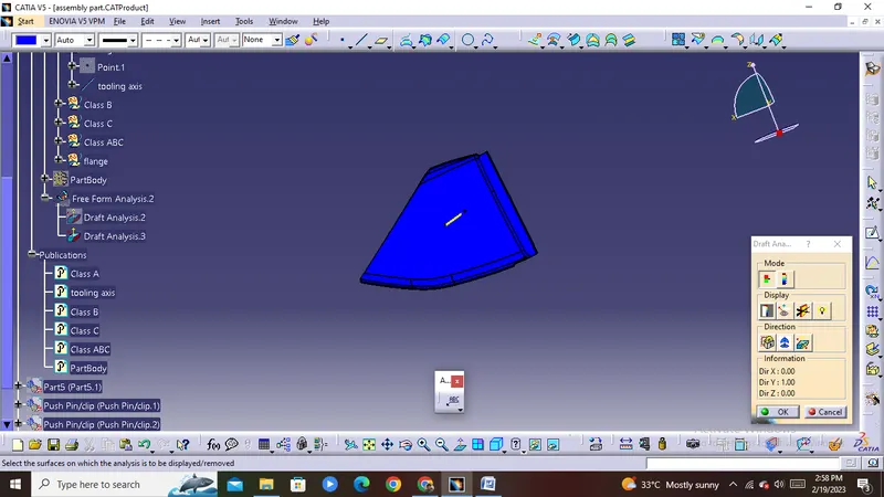
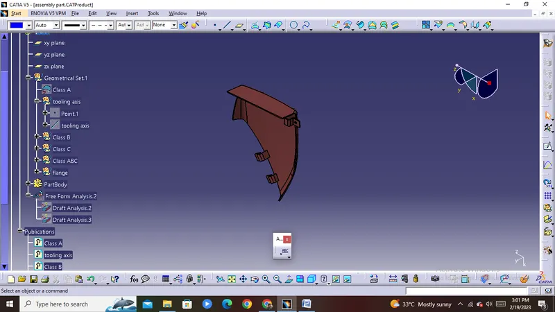
cretaion of solid body
by using the closed surface create a closed final solid body
BOTTLE HOLDER:
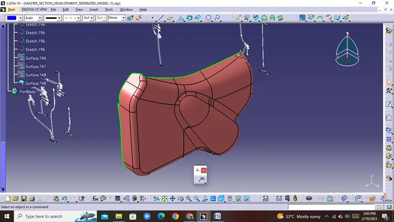
class A
class A surface is given by styling team
 ]
]
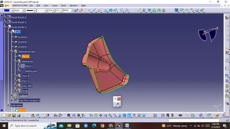
CREATION OF TOOLING AXIS:
The line has been created using the line command. The point-direction option is used to create the main tooling axis in the Y-direction.
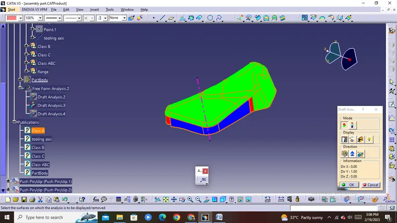
draft analysis on class A
do the draft analysis for the class class A surface withe help of tooling axis
--change the material conditon to materialstic mode
--go to insert ,click on analysis ,select feature draft analysis
--drag the compass on to the tooling axis
--adjust the compass and click on the lock command
--after that select the surface
--the draft angle may be maintained at 3°
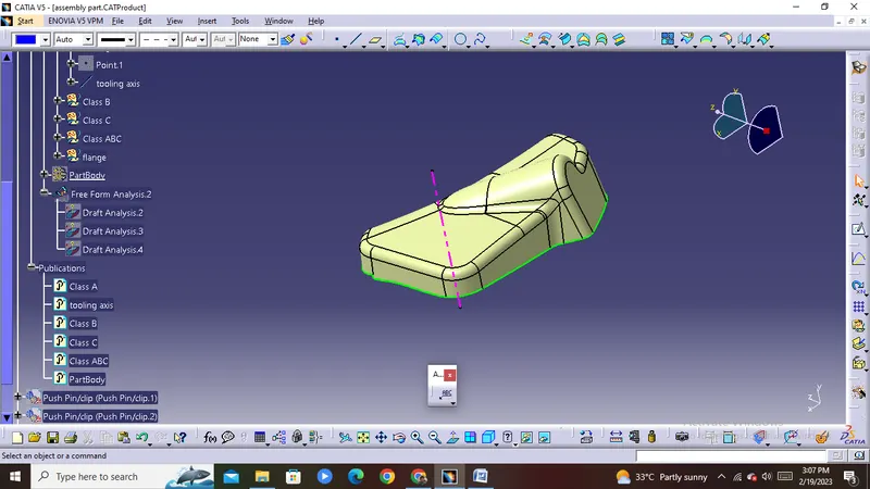
CREATION OF CLASS-B SURFACE:
class B surface can be created by off setting the class A surface with a distance of 2.5mm with the help of offset command.
--after offseting there will be some gap will be come that can be completed by using spline,boundary, multisection and sweep comands
creation of class C
by using the extract command extract ,extract the boundaries of the class A surface.
--with the help of sweep command add the material to the boundary that are extracted
--Due to surface irregularities, it was not possible to create a single sweep. Hence, several sweeps and multisection were created, and finally, they joined together to create a class C surface
--with the helpof join command join all the sweeped material
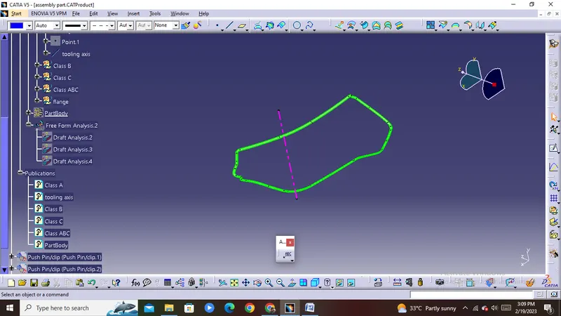
creation of class ABC
join the class A and class c surface and named it as AC
--join the AC surface to the B surface
-- by joining them the closed surface will get
--The join of Class A and Class C surface is trimmed with class B surface to create a closed surface. While performing trim operation errors were coming as a proper intersection was not happening. Hence with the help of extrapolating command class B surface was extrapolated and finally trimmed.
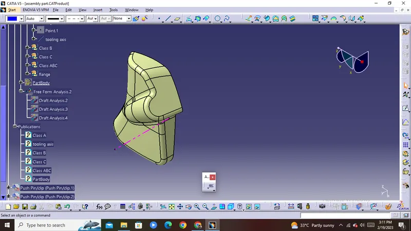
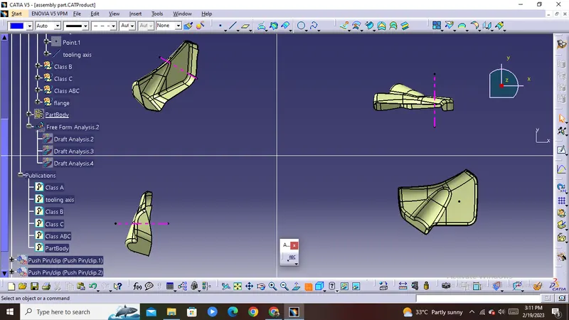
creation of solid body
after creating the ABC surface with the help of closed surface command create an an closed solid part body
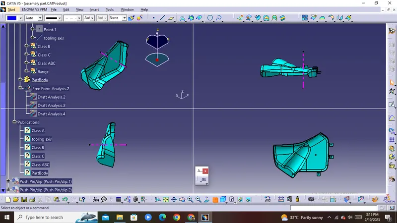
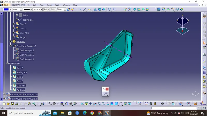
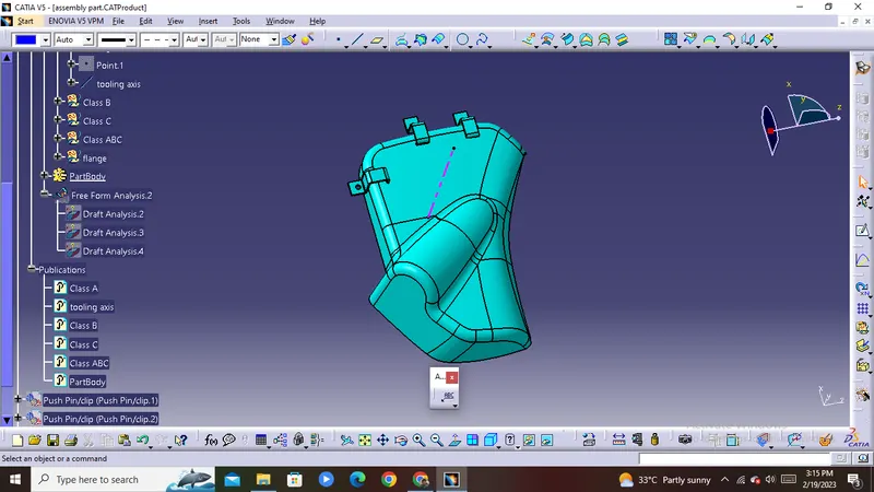
B-SIDE FEATURES
flanges
Flanges are the elements that are used or needed to join different components together.to join the all parts together inn here flanges are need to made on the following parts
door Armrest
Map pocket and
Bottle holder
--Following the master section, given as the input basically the measurements and location of the flange.
--For creating the flanges take extraction of the curve and made a point on that curve then create one plane on that point followed by creating a sketch on that plane take the point created as the origin.
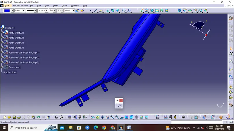
fig:flanges of door arm rest
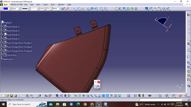
fig:flanges on map pocket
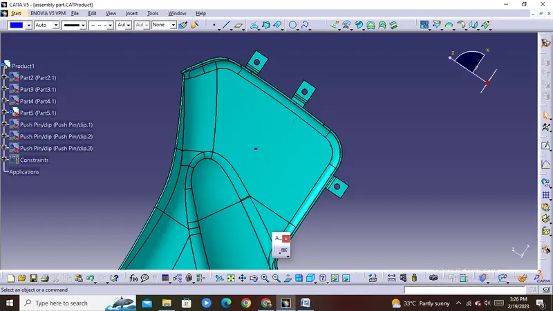
fig:flanges on bootle holder
DPG HOUSE
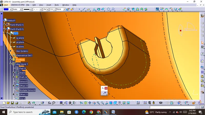
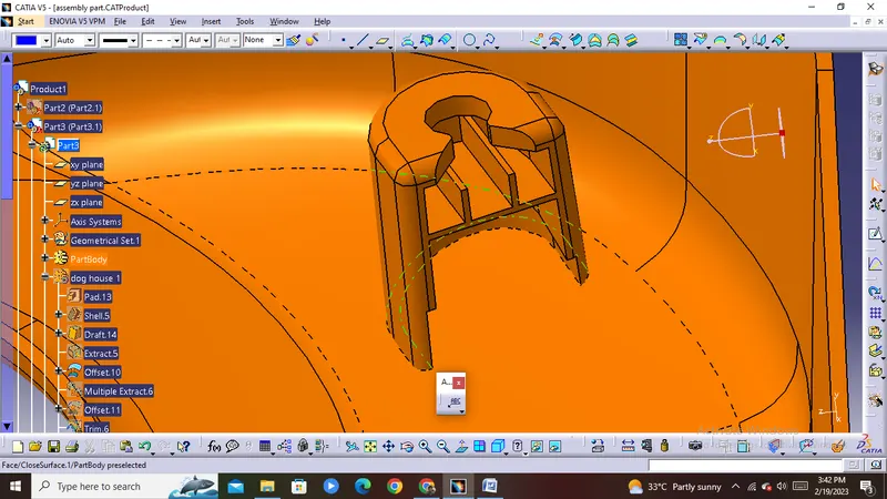
dog houses are an engineering features in plastic design which are used as an supporting features
--do house and other b side features are created on ClassB surface
--Dog houses are subjected to draft analysis to prevent breakage of the component during ejection from the mold cavity
--in this door panle the dog houses are only mounted on lower substrate
--So for creating the dog house I have extracted the base surface of the lower substrate and made a point that extracted surface and sketched on it.
--Then I have swept the above sketch along the tooling axis of the lower substrate giving 1.5 degrees of the draft.
--For this purpose, I have just offset the base of the lower substrate to a height of 4mm the value could be anything between 3-6mm and then I have extracted the inside portion of the dog house.
Then I have extrapolated the inside portion that extracted and trimmed it with the base.
PUSH PINS
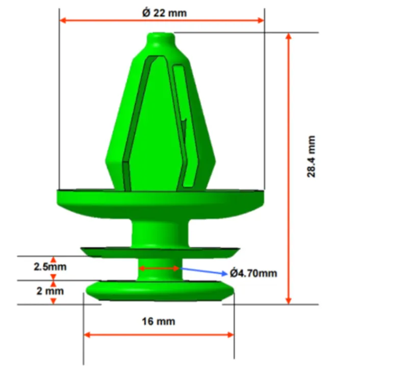
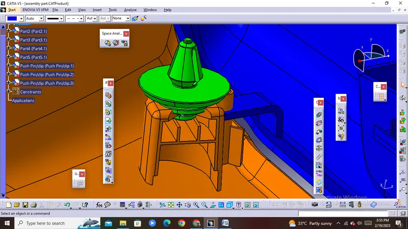
--push pins are used to join one component to other in here push pins are inserted or attached to dog house
--the dimesions are taken from the below shown figure reference
ASSEMBLY OF PUSH PIN
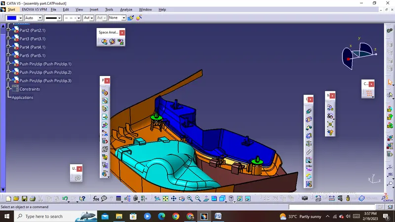
the push pin is assembled to the dog house by using the coincide constraint and contact constraint the below fig will show the assemblage of push pi
HEAT STAKE and RIBS
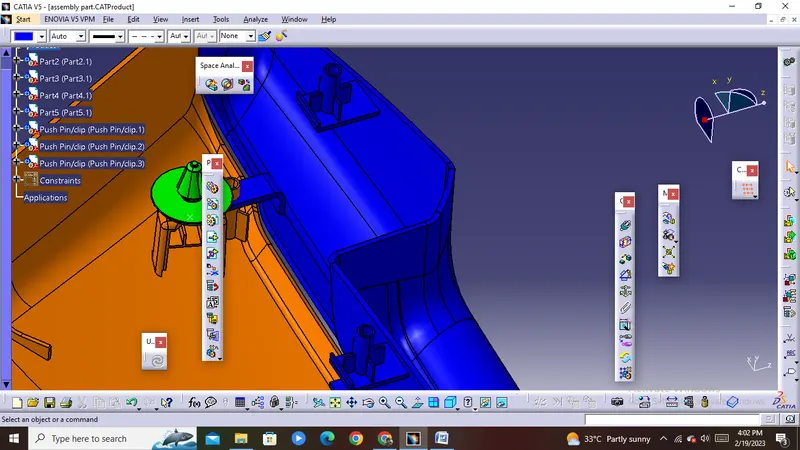
heat stake is permenant joint techninque .in here heat stake is used to join the two plastic components
Heat staking also known as thermoplastic staking is the process of joining two dissimilar materials together. In heat staking we use local heating and cooling to raise the temperature of plastic components and allow plastic reforming to be carried out. This reforming can be used in a wide variety of applications.
RIBS
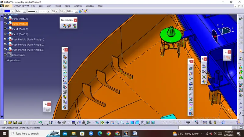
--the ribs are created on lower substrate
--Ribs are thin, wall-like features typically designed into the geometry of a part to add internal support to walls or other features like bosses. In a similar fashion, gussets are support features that reinforce areas such as walls or bosses to the floor.
ASSEMBLY
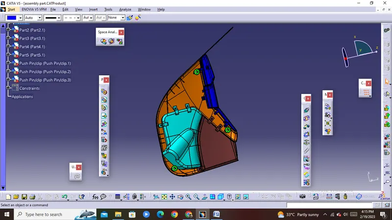
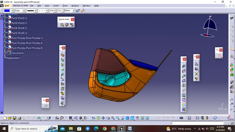
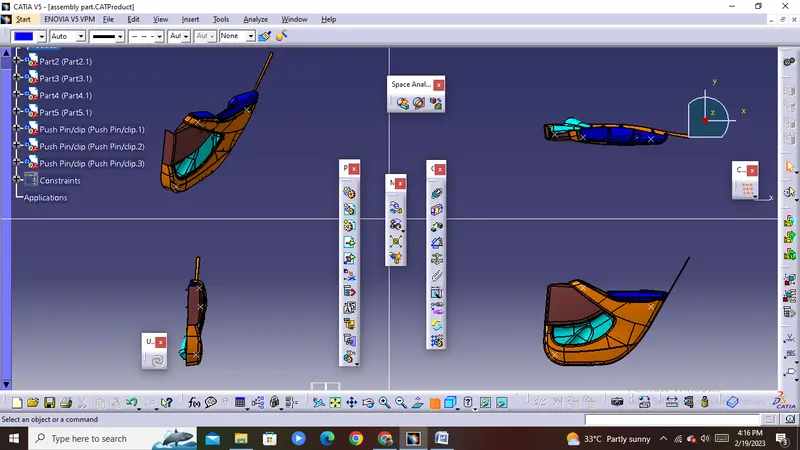
after all doing this final stage is assembling the all parts
--the assembly process is done by the tools available in catia v5 like coincidence ,contact,and offset
--firstly the lower substrate is fixed then the other parts are attached to the lower substrate by using above commands
below figures will show the final component
conclusion
The door trim panel was sucessfully designed as per the OEM standards used in automotive industry in CATIA V5