CREATION OF BUTTERFLY VALVE AND APPLY GD&T
AIM :
The main moto of this project is to design the assembly of the Butterfly valve and apply the GD&T concepts to the various parts of the Butterfly Valve
SOFTWARE USED :
CATIA V5
INTRODUCTION
GD&T SYMBOLYS
GD&T gives manufacturers a clear understanding of the tolerances for a specific part. It provides the maximum amount of tolerance for the part to function properly, which reduces part complexity so that you aren't overspending for a minimum tolerance that you may not need.
GD&T allows you to convey substantial information about your part’s design using a relatively small amount of letters, numbers, and symbols. No long paragraphs of explanation necessary! The ability to communicate efficiently reduces back and forth between you and the contract manufacturing service you are working with.
Since GD&T is such a precisely articulated system of language, it minimizes ambiguity in the description of a parts design. As a result, you can be confident that your part will be manufactured with the highest degree of accuracy and work as intended in the field
BUTTERFLY VALVE:
A butterfly valve is from a family of valves called quarter-turn valves. In operation, the valve is fully open or closed when the disc is rotated a quarter turn. The "butterfly" is a metal disc mounted on a rod. When the valve is closed, the disc is turned so that it completely blocks off the passageway.When the valve is fully open, the disc is rotated a quarter turn so that it allows an almost unrestricted passage of the fluid. The valve may also be opened incrementally to throttle flow.Butterfly valves are used where space is limited. Unlike gate valves, butterfly valves can be used for throttling or regulating flow as well as in the full open and fully closed position. The pressure loss through a butterfly valve is small in comparison with the gate valve.
butterfly valve consisit of the following parts
1. Body
2. Shaft-Stem
3. Top Flange
4. Disc Plate
5. Lever Handle
6. Nut
Advantages of Butterfly valves-
- Compact design requires considerably less space, compared to other valves
- Light in weight
- Quick operation requires less time to open or close
Disadvantages of Butterfly valves-
- Throttling service is limited to low differential pressure
- Cavitation and choked flow are two potential concerns
Common Applications of Butterfly valve:
--food processing
--refiners
--shut off valves
--ship building
Methodlogy
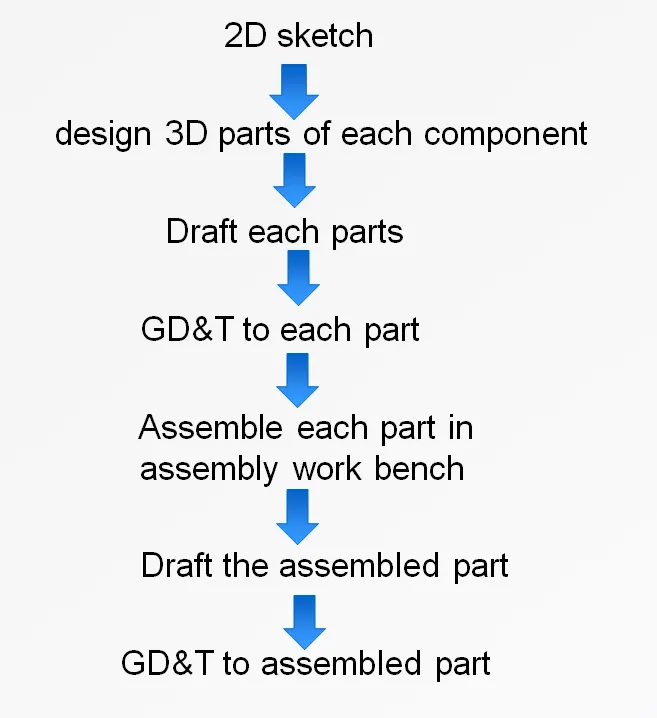
Description of tools/ Features used for designing as shown as following:
- Creating 2D Sketch:- Creating 2D sketch for Base thickness part.
- Line :- Line is one of the most basic commands inCATIA. line command is used to draw the straight lines or surfaces
- Arc/Circle:- this command is used to create associative arcs and circle features. The type of arc you get depends on the types of constraints you combine. You can create many types of arcs by combining different types of constraints.
- PAD &POCKET:-PAD is a command which add the material by extruding the 2d sketch and POCKET is the command which removes the material
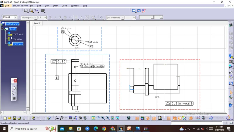
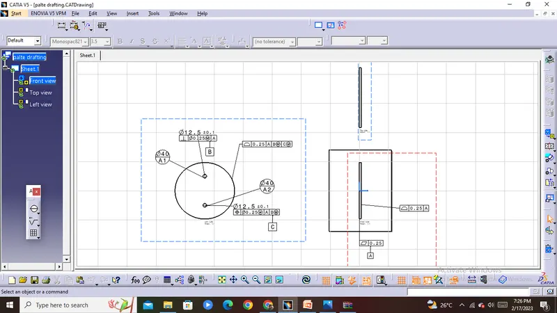
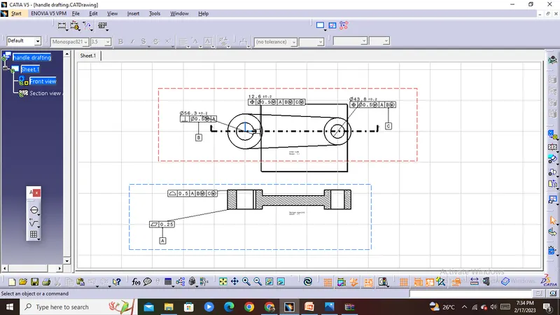
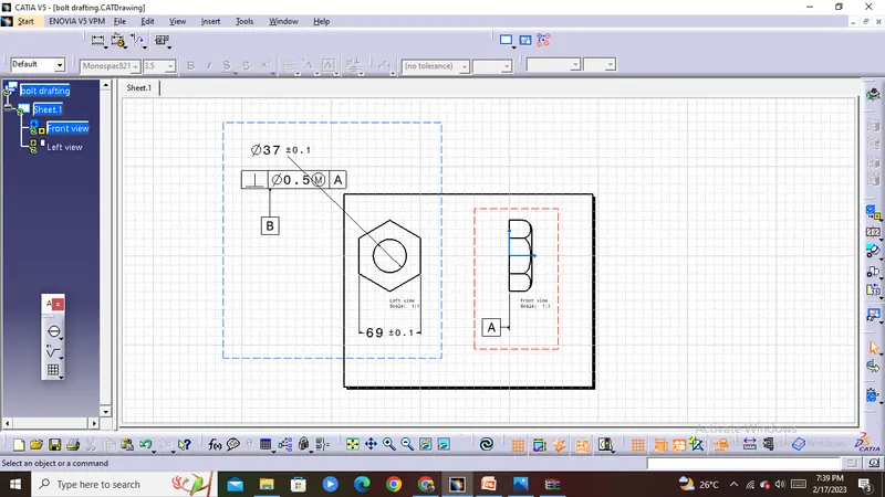
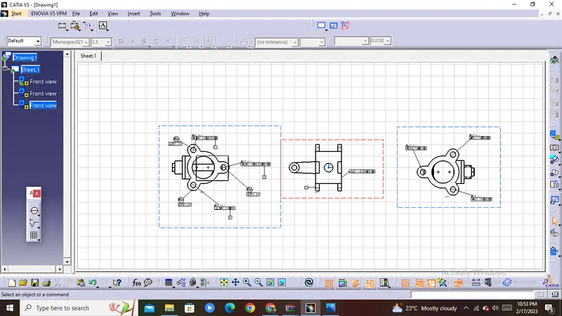
- Drafting:- Quickly and easily create engineering drawings from 3D models using highly efficient drafting tools. The drafting software automatically creates drawing views from 3D part and assembly models, and helps you align and scale drawing views and arrange drawing sheets.and drafying also used for applying the gd&t symbols
butterfly valve parts
1. Body
2. Shaft-Stem
3. Top Flange
4. Disc Plate
5. Lever Handle
6. Nut
BODY:
The wafer-style body is the more cost-effective of the two. It is connected to the pipes via bolt holes that run through the valve’s body. This design is simple to install and is primarily used in universal flow systems to prevent backflow. It should be noted, however, that they are not recommended for use in regulated systems.
B.Lug style butterfly valves are slightly more expensive than their counterparts, but they provide several distinct advantages. Lug butterfly valves connect to the pipe via protruding lug holes on the outside of the valve’s body. Unlike the wafer valve, the valve in this design actually helps carry the weight of the piping throughout its body. This enables dead-end servicing by removing piping from oneside of the valve
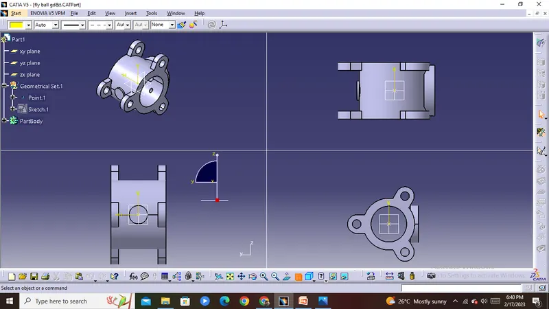
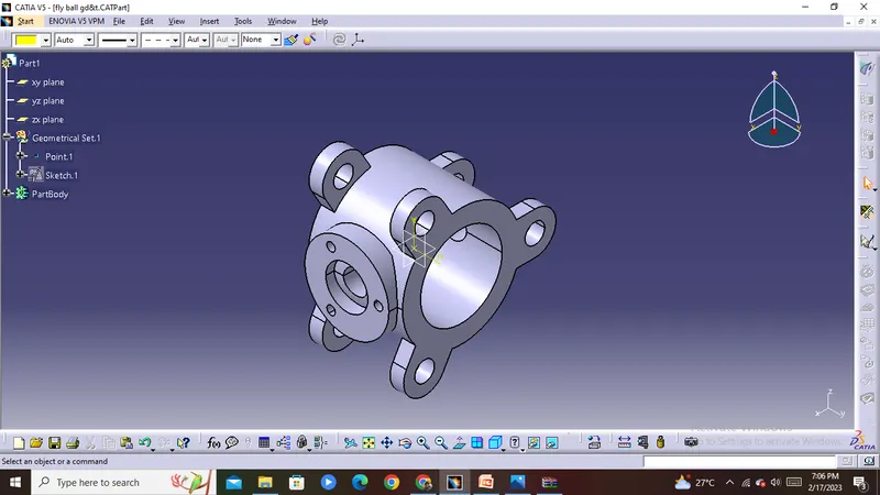
The one of the major component in butterfly valve is body that is fit between two pipe flanges. The following sets of the command used for Body designing in catia.
sketch
PAD
counterboring
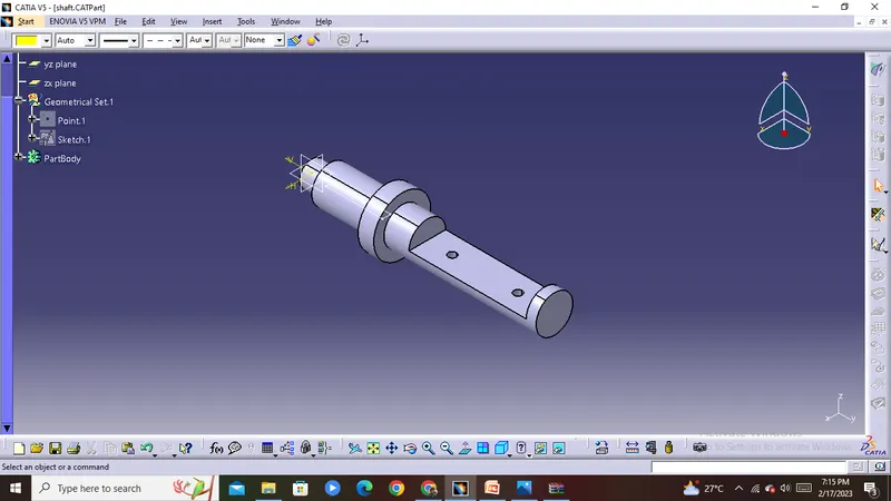
Shaft:
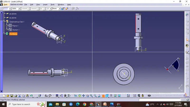
To held the disk in proper position, the stem must extend beyond the bottom of the disk and fit into a bushing in the bottom of the valve body.the disc plate and handle(lever)will be assembeld to the shaf.the stem is connects the disk on the inside to the handle on the outside. Without it, the valve would be unable to open or close
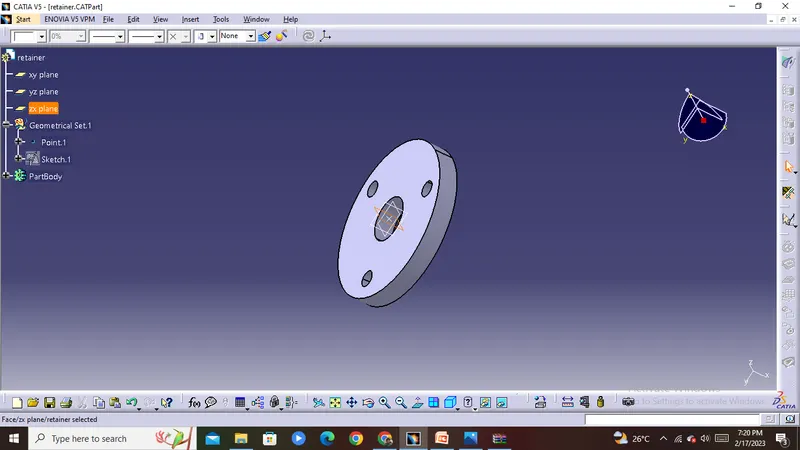
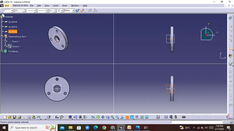
Retainer
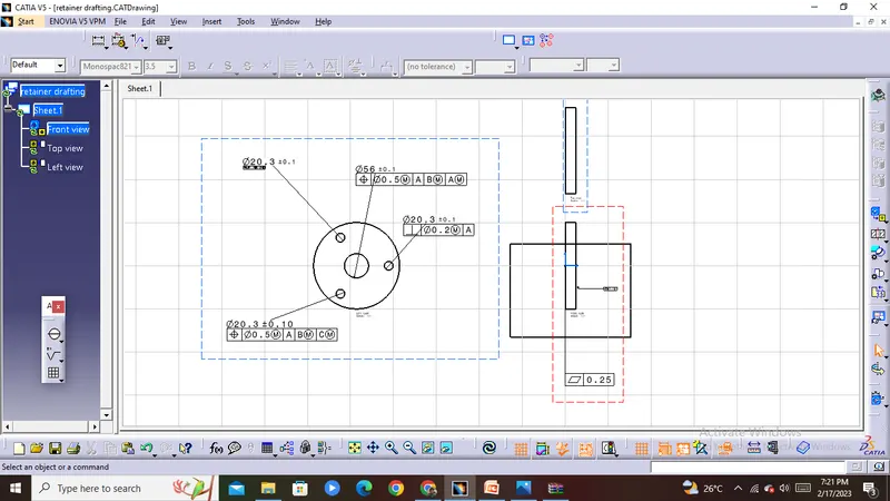
retainer is a kind of washer which is fixed to the butterfly valve the commands used to draw the retainer is
sketch
pad
Disc plate
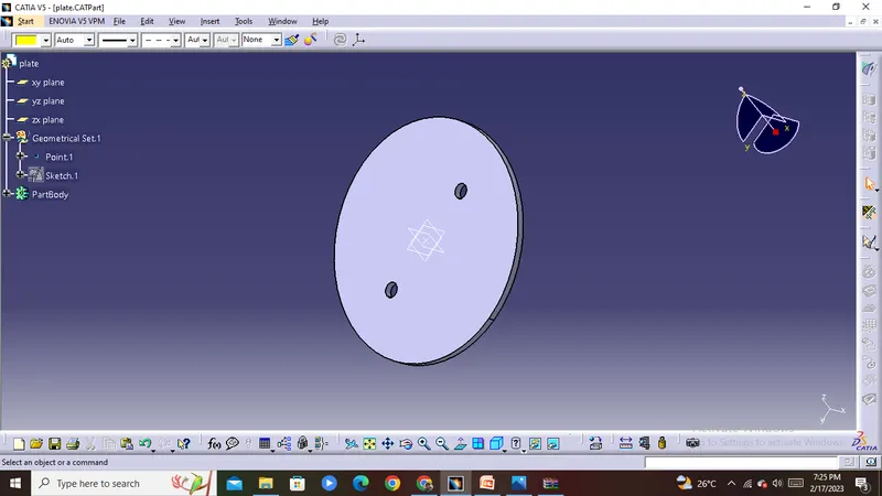
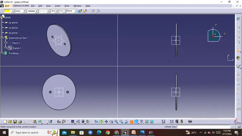
The butterfly valve opening and closing part is a disc-shaped butterfly plate, which rotates around its own axis in the valve body, so as to achieve the purpose of opening, closing or adjusting.
It plays a vital role in the entire valve structure. It can be operated by the handle or by turbine, pneumatic, electric and other equipment. The quality of the valve disc determines the overall performance of the valve.
The smoothness of the contact surface between the valve disc and the rubber seat determines the quality of the valve’s tightness.The valve disc is the opening and closing piece that controls the flow and circulation of the medium.
When valve is fully opened or closed the disc is rotated a quarter turn.Disc is mounted on shaft. When the valve is closed, the disc is turned so that it completely blocks off the passageway
tools used to draw the disc plate is same as the retainer
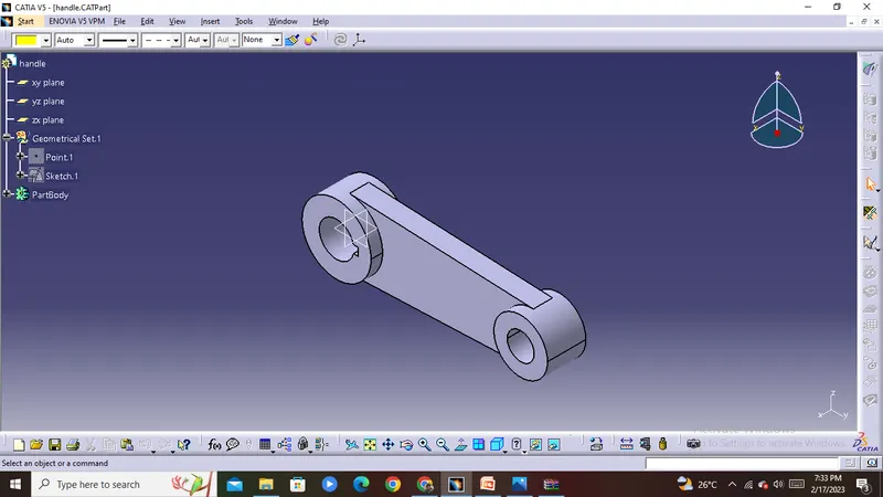
LEVER or HANDLE
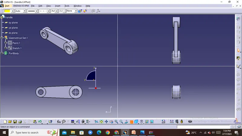
the handle is mounted at the end of the shaft and it is cantacted to retainer .the handle is used to rotate the shaft and get the required motion for valve opening and closing .Hand lever is usually used in small sized Butterfly valves.It provides ease of operation at the expense of speed. It can be adjusted to various positon with the help of the gearbox.
to create the handle follow the below steps
- Create two circular sketches with the appropriate diameters, and specify a suitable distance between them. Also, create a keyway slot in the bigger diameter sketch. Join these two sketches with a line tangent to both the circles.
- After creating the fully constrained sketch, first, extrude the circular regions and then extrude the mid-section with different thickness values.
- Then combine all the features using Unite command. Then create a drawing sheet of the model and apply GD&T to the drawing
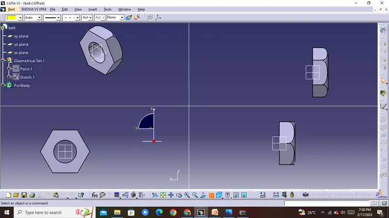
Nut
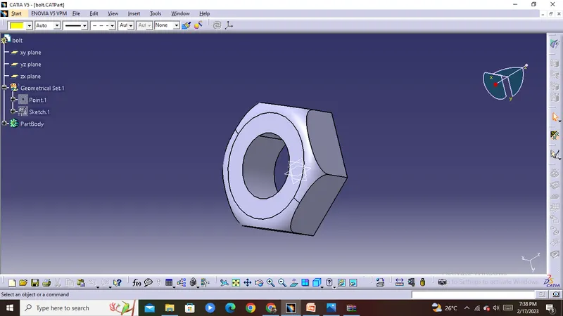
it mounted at the end of the shaft to hold the handle and retainer in its position
ASSEMBLY
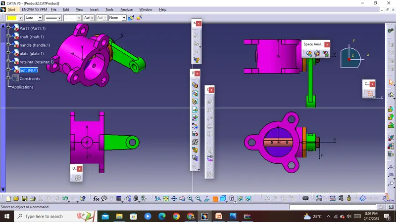
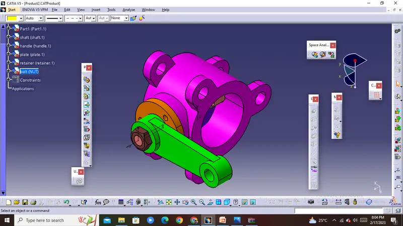
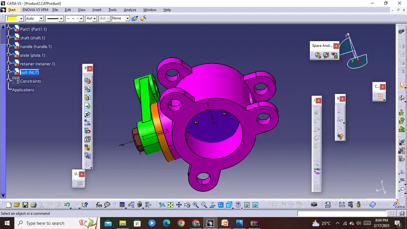
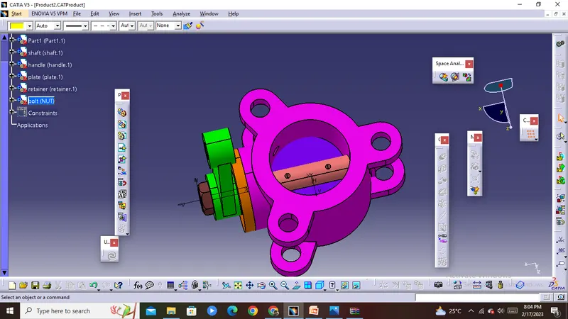
--After drawing the each part of the butterfly valve all parts should assembeld in catia v5
--the modeld parts should be assembeld with appropriate constraints
--firstly we need to fix the body then the other parts will be attached to it with the help of tools provided in catia
--firstly shaft is attached to the body by using coincidence and contact or offset constraints
---then the disc plate is attached to the shaft at the place where the shaft has a cut with the helo coincidence and contact constrants provide by the catia
--then attach the retainer at the end of the shaft by using coincidence and contact constraints the contact constarint should be given between retainer surface and body surface
--after this attach the handle at the end of the shaft by using the above constraint provide by the catia.
--finally assemble the Nut to the shaft
CONCLUSION
The Butterfly valve is successfully created and GD&T is applied to all the different parts and the assembly of the Butterfly valve