CREATION OF BASE BRACKET
Aim:To create a Base Bracket Plastic Component through a given Class A Surface and perform Draft Analysis on the final plastic component.
Objectives:
- Creation of Tooling Axis.
- Creation of Class B and Class C surface.
- Creating a solid part out of surface modeling
- Draft Analysis of Class A surface and final plastic component.
Tool Used: CATIA V5
Introduction: In this project we are designing a base bracket using given class A surface. The approach includes creation of Class B surface keeping 2.5 mm thickness in mind for the complete component. The design also included Class C creation from the given parent surface.
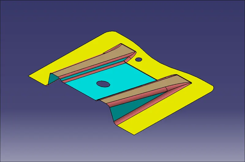
Class A:
Class A surface are primary used in the automotive environment and rrefer to these surfaces which are visible to outside world or to the humans..Class A surfaces are those surfaces ,which are vivible to us (interior/exterior) and have an shape and high surface quality
Class B
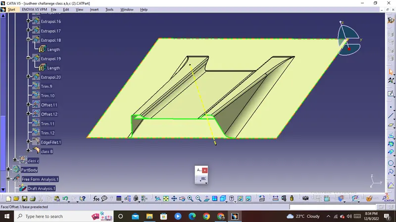
class B are secondary surfaces that goes fee sometimes ,but are less impoortant sucha s the inside of your glovebox,ash tray etc., these must be smooth and as well ,but aare not held to the standard thst class A surfaces
Class C
class C surface is the thickness between the class A and class B ,so there is no need of high end finishing in class c surfaces
Steps in creating class A ,class B, Class c surfaces:
step1: creating rotating axis
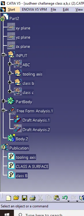
Go to insert--geometrical set parent and then define the tooling axis
after that creat a point with the help of point command
then creat a line and make it as axis and chose the direction of the axis as z -axis
step2: performing draft analysis
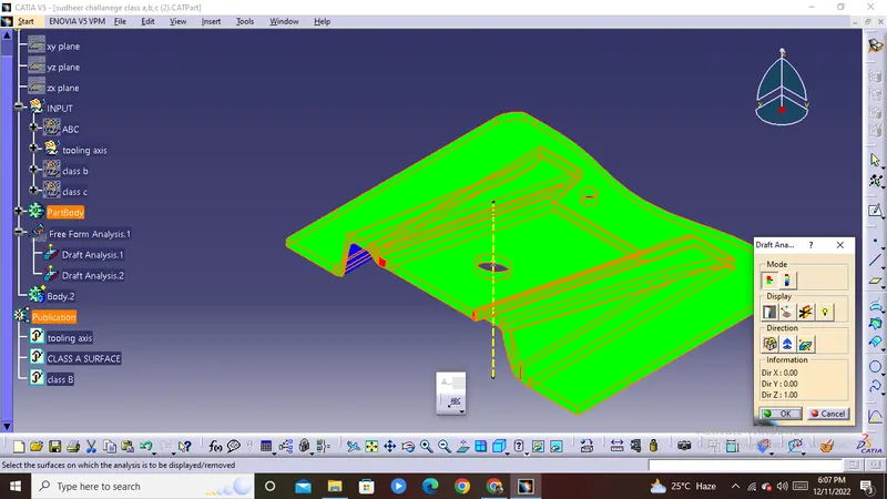
change the mode of view into materialistic mode--Go to insert -- click on analysis-- feaured draft analysis
after that drag the mini robot(direciton axis system) on to the axsis that we created
click direction symbol and adjust the mini robot on the same axis
then lock the direction with the help of lock command
self the surface which need to be done draft analysis
Step3: Publication
select CLass A surface -- tooling axis--click on publication
click on yes ,and click on ok
Do the other publictations for class A ,Class B and Class ABC surfaces
step4: creation of class b surface
Insert--geometrical set(class B) under geometrical set1--define class B
with the help of the following commands done the class B
*extract
*surface trim
*extrapolate
*off set
*trim
extract select (all the 6 sides that are need to be extracted and go on with no propagation mode) and then ok
click on untrim,select the required extraction hide it do extraction for all the faces and then hide them
click on extrapolation ,click on edge ,go with point continuty and do extapolation for all extracted elements
clcik on offset and select the extrapolated surface and do 2.5 mm off set
then trim the surface according to the class A with the help of trim command
step5: creation of class C
insert geometrical set--under(input) and click on ok
define class C,click onboundary condition select the boundary and select limit 1 and limit 2 click on ok
click on sweep surface --click on second sub type--with draft direcrtion--give 3 degrees and select the required direction
repeat the same curve on 2nd curve
join the two surfaces extrapolate the two unjoined surfaces and trim them to get joined surface
to get the holes on top surface,click these and creat boundaries and sweep that both
step 6:creation of ABC
click on insert geometrical set AC under input and then click on ok
--Define the ABC
join everything(class A,class C,class B) using join command
after joing all publish class c
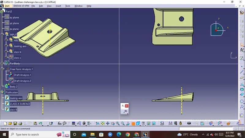
step 7:
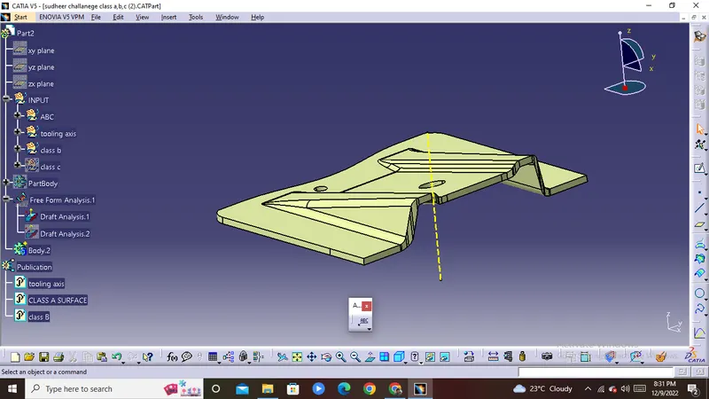
check the part whether there is any boundaries in the part after make the part as solid
Define the part body ,click on closed surface command and then click on the part body to get the solid model
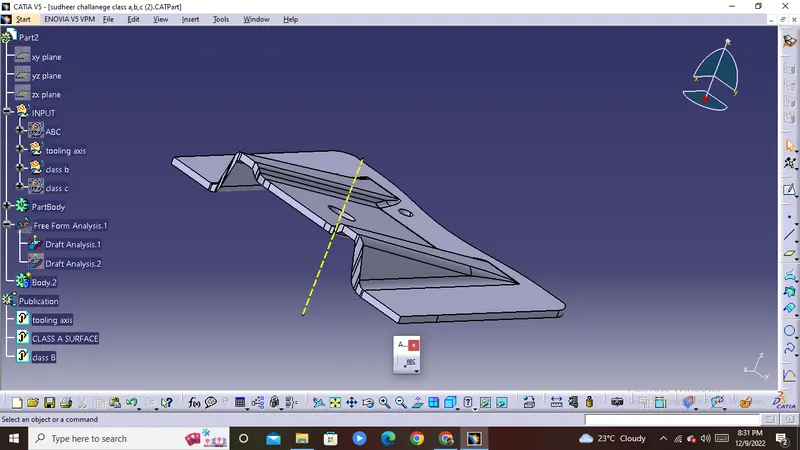
perform draft analysis for final product
repeat the steps of draft analysis to make the draft analysis on final part
CONCLUSION
The base bracket was sucessfully completed as per the standards