DESIGN OF SUPRA SAEINDIA STUDENT FORMULA CHASSIS
DESIGN OF SUPRA SAEINDIA STUDENT FORMULA CHASSIS
SUBMITTED BY - MANAS PATIL
PROJECT MENTOR - CHIKKAM SRIKANTH
Abstract: SUPRA SAEINDIA is an annual national level competition organized by the Society of Automotive Engineers India. From all over India, the selected Under Graduate & Post Graduate Engineering Student teams are asked to design, model, fabricate and compete with a small open-wheel, open cockpit type race car. The major challenge posed is to design and fabricate a light weight car without compromising the safety of the driver. The car has to be rigidly fabricated at minimal expense. The design is based on the anthropological data of the specified human (95th percentile male) allowing fast ingress and egress from the car. CATIA V5 CAD software is utilized for the design of the chassis because of its exceptionally powerful capability in the field of design and analysis of engineering products. The entire design process is based on SUPRA SAEINDIA 2020 rule book.
INTRODUCTION:
SUPRA SAEINDIA Student Formula is a national level student competition, organized by the Society of Automobile Engineers India, where students from various colleges from all over India participate to develop, design, fabricate, test and manufacture an open wheel racing car to compete with other teams. The challenge to teams is to develop a vehicle that can successfully compete in all the events described in the Student Formula Rules. The competitions themselves give teams the chance to demonstrate and prove both their creativity and their engineering skills in comparison to teams from other universities around the world. The vehicle must accommodate drivers whose stature ranges from 5th percentile female to 95th percentile male and must satisfy the requirements of the Student Formula Rules. The vehicle must totally be in compliance with the design rules mentioned in the rulebook in order to clear Technical Inspection (TI) round.
COMPONENTS AND PARTS OF THE CHASSIS:
Primary Structure:
- Front Bulkhead
- Front Bulkhead Support
- Main Roll Hoop
- Front Roll Hoop
- Side Impact Structure
- Roll Hoop Bracings
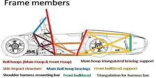
DEFINITIONS OF FRAME MEMBERS:
- Main Hoop - A roll bar located alongside or just behind the driver's torso.
- Front Hoop - A roll bar located above the driver's legs, in proximity to the steering wheel.
- Roll Hoops - Both the Front Hoop and the Main Hoop are classified as "Roll Hoops"
- Roll Hoop Bracing Supports - The structure from the lower end of the Roll Hoop Bracing back to the Roll Hoop(s).
- Frame Member - A minimum representative single piece of uncut, continuous tubing.
- Frame - The "Frame" is the fabricated structural assembly that supports all functional vehicle systems. This assembly may be a single welded structure, multiple welded structures or a combination of composite and welded structures.
- Primary Structure - The Primary Structure is comprised of the following Frame components: 1) Main Hoop, 2) Front Hoop, 3) Roll Hoop Braces and Supports, 4) Side Impact Structure, 5) Front Bulkhead, 6) Front Bulkhead Support System and 7) all Frame Members, guides and supports that transfer load from the Driver's Restraint System into items 1 through 6.
- Major Structure of the Frame - The portion of the Frame that lies within the envelope defined by the Primary Structure. The upper portion of the Main Hoop and the Main Hoop Bracing are not included in defining this envelope.
- Front Bulkhead - A planar structure that defines the forward plane of the Major Structure of the Frame and functions to provide protection for the driver's feet.
- Side Impact Zone - The area of the side of the car extending from the top of the floor to 350 mm (13.8 inches) above the ground and from the Front Hoop back to the Main Hoop.
MATERIAL SELECTION:
The material used to build the chassis is steel. Steel has high strength properties and can be easily welded. Circular seamless steel pipes of OD 25mm and having thickness ranging from 1.5mm to 2.5mm are used.
GENERAL DESIGN RULES & REQUIREMENTS
The general rules and requirements followed to design the chassis are according to the SAEINDIA Student Formula 2020 rulebook.
Wheelbase:
The car must have a wheelbase of at least 1525 mm (60 inches). The wheelbase is measured from the center of ground contact of the front and rear tires with the wheels pointed straight ahead.
Minimum Material Requirements:
The Primary Structure of the car must be constructed of either round, mild or alloy, steel tubing of the minimum dimensions specified in the following table. Only seamless pipe to be used.
|
ITEM or APPLICATION |
OUTSIDE DIMENSION X WALL THICKNESS |
|
Main & Front Hoops, Shoulder Harness Mounting Bar |
Round 1.0-inch (25.4 mm) x 0.095 inch (2.4 mm) or Round 25.0 mm x 2.50 mm metric |
|
Side Impact Structure, Front Bulkhead, Roll Hoop Bracing, Driver's Restraint Harness Attachment |
Round 1.0-inch (25.4 mm) x 0.065 inch (1.65 mm) or Round 25.0 mm x 1.75 mm metric or Round 25.4 mm x 1.60 mm metric or Square 1.00-inch x 1.00-inch x 0.049 inch or Square 25.0 mm x 25.0 mm x 1.25 mm metric or Square 26.0 mm x 26.0 mm x 1.2 mm metric |
|
Front Bulkhead Support, Main Hoop Bracing Support |
Round 1.0-inch (25.4 mm) x 0.049 inch (1.25 mm) or Round 25.0 mm x 1.5 mm metric or Round 26.0 mm x 1.2 mm metric |
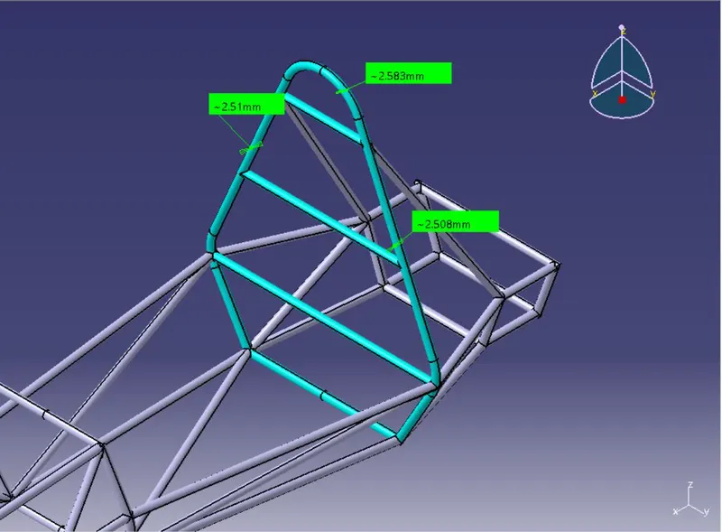
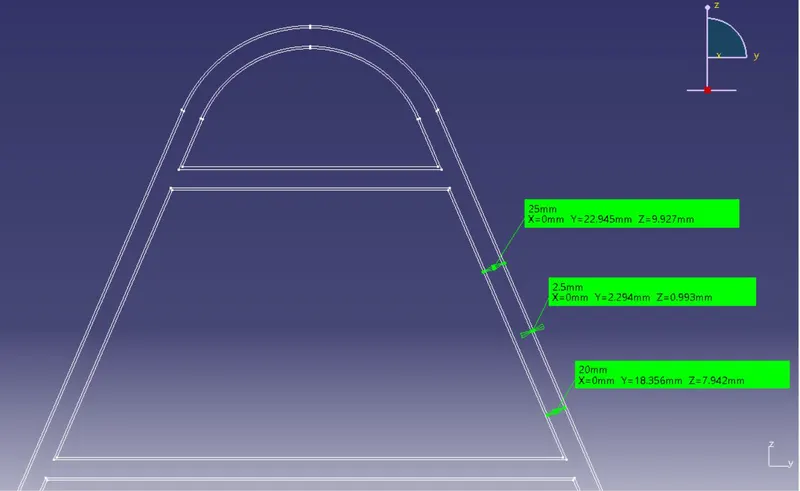
For Main Roll Hoop: -
Thickness = 2.5mm
OD = 25mm
ID = 20mm
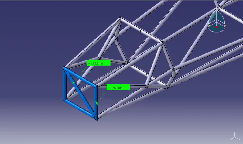
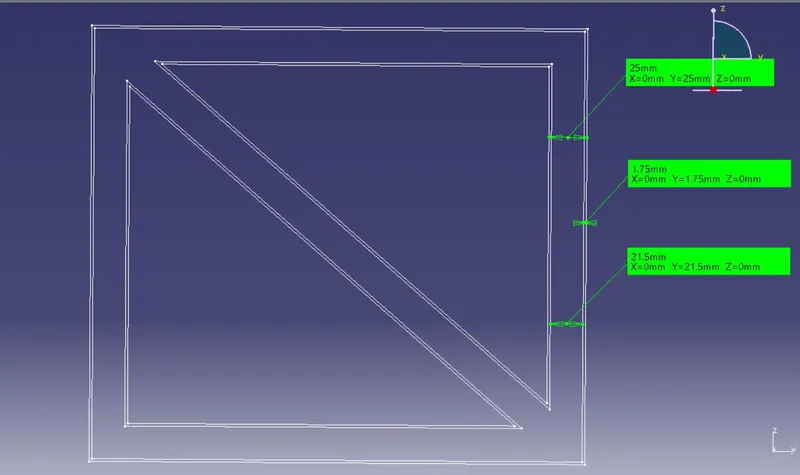
For Front Bulkhead: -
Thickness = 1.75mm
OD = 25mm
ID = 21.5mm
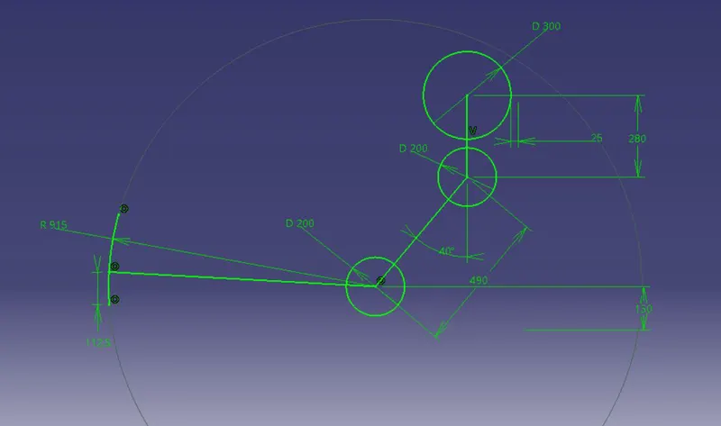
95th Percentile Male Template:
The 95th Percentile Male Template gives perspective of seating location for the occupant. It is a two-dimensional template used to represent the 95th percentile male. The chassis should be designed considering the 95th percentile male template dimensions.
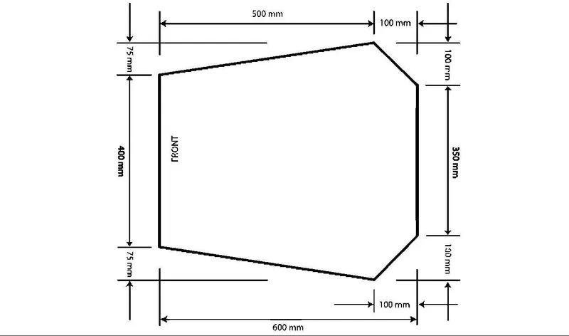
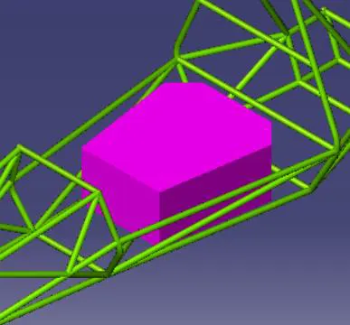
COCKPIT TEMPLATE:
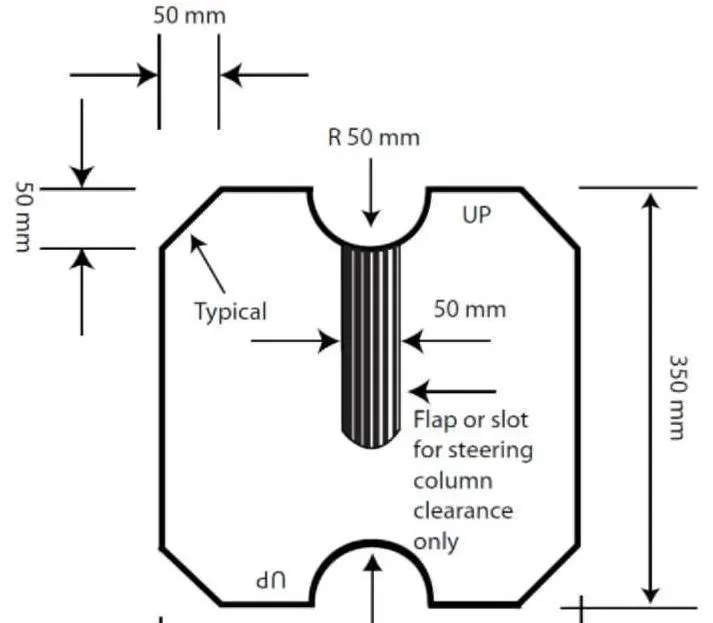
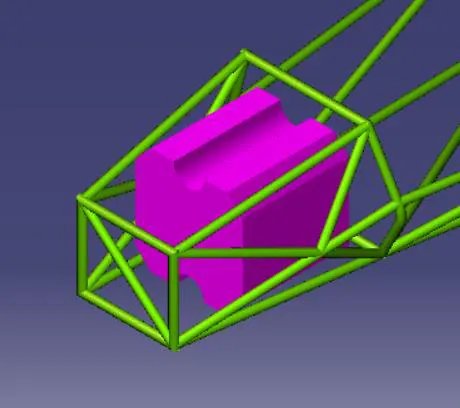
In order to ensure that the opening giving access to the cockpit is of adequate size, a template shown below will be inserted into the cockpit opening. It will be held horizontally and inserted vertically until it has passed below the top bar of the Side Impact Structure.
STEERING TEMPLATE:
The template, with maximum thickness of 7mm (0.275 inch), will be held vertically and inserted into the cockpit opening rearward of the Front Roll Hoop, as close to the Front Roll Hoop as the car's design will allow.
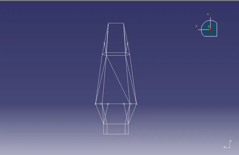
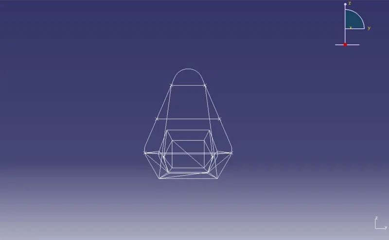
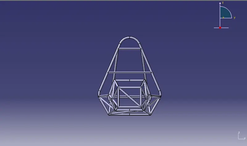
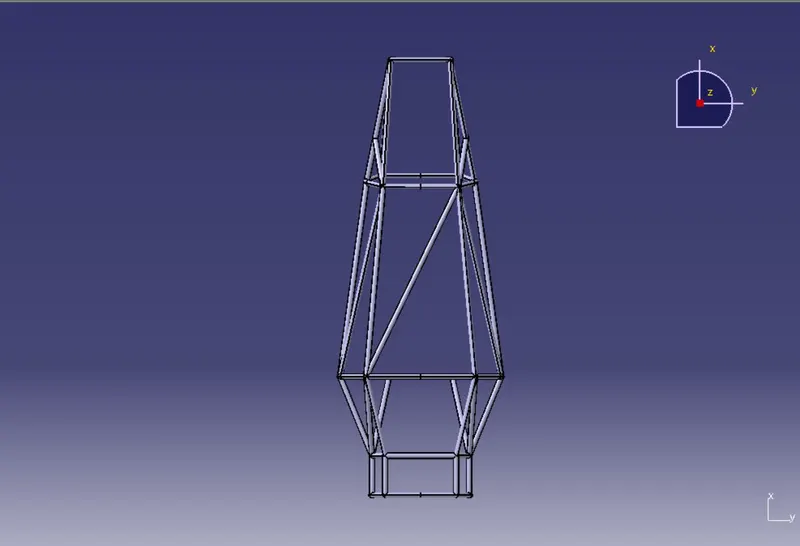
WIREFRAME DIAGRAM:
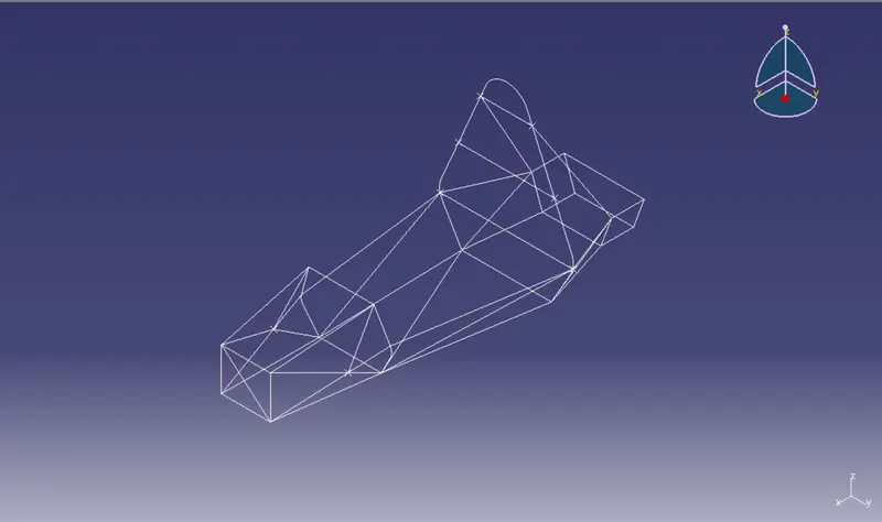
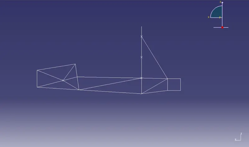
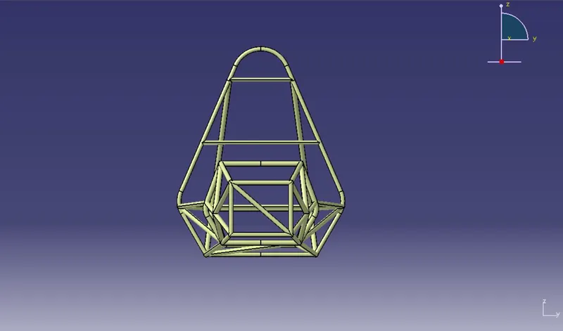
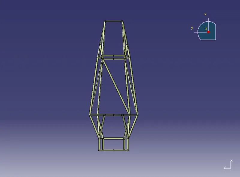
The wireframe diagram was developed by creating sketch planes and then joining these sketches by point-to-point lines.
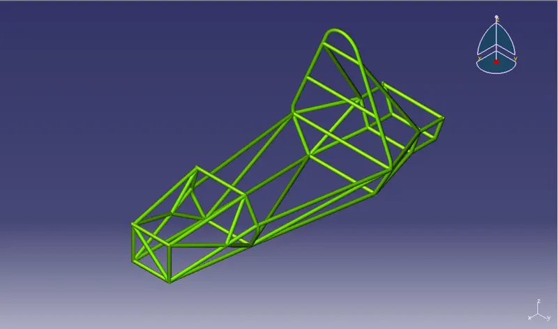
SURFACE MODEL:
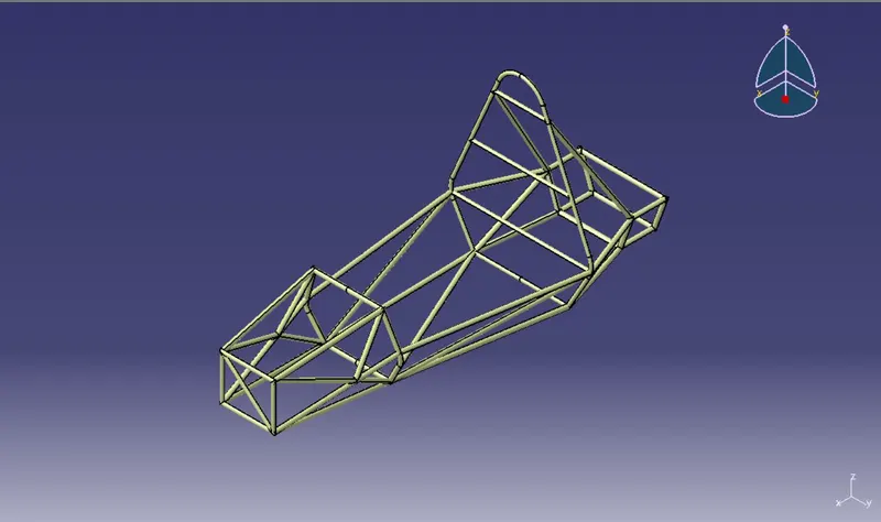
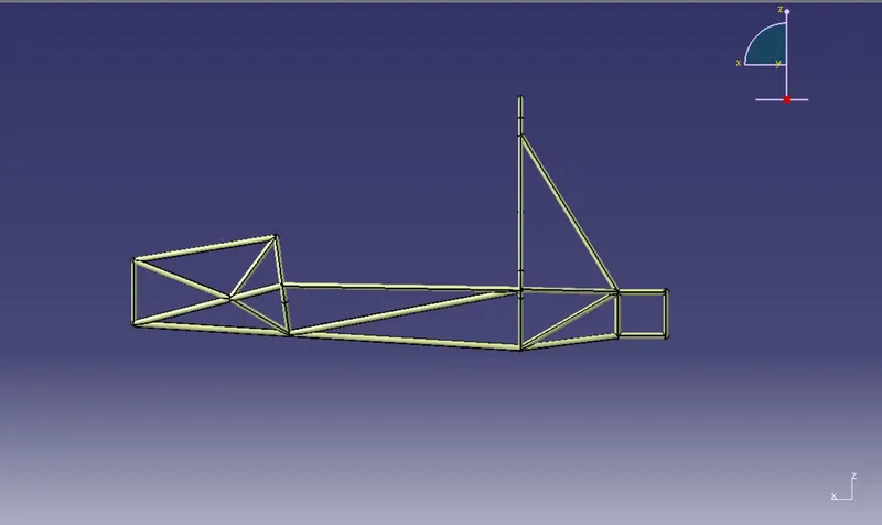
The surface model was created by forming seamless thin circular tubing along the wireframe diagram using the sweep command. The circular surface i.e., the thin round tubes are of 25mm diameter throughout. The diameter for all the structural members remains same.
SOLID MODEL:
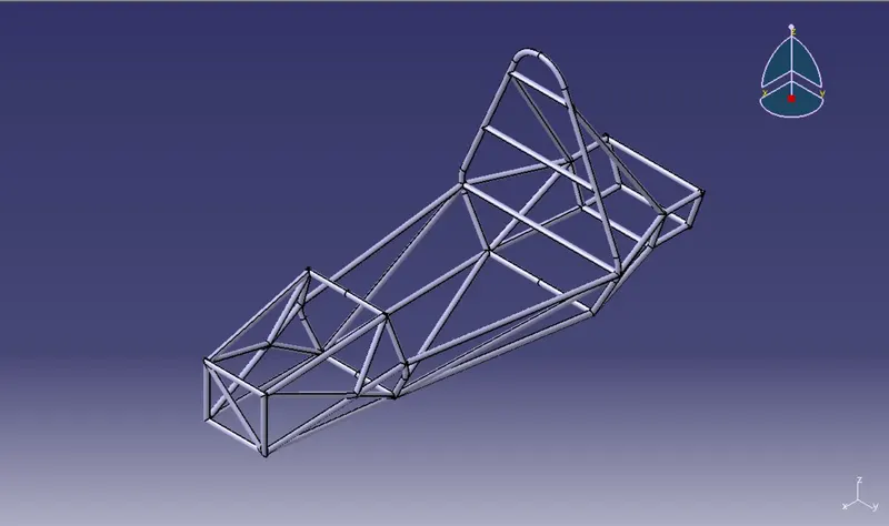
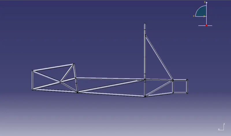
The solid model was developed by adding thickness to the surface model which makes the chassis solid and thick. The thickness for each structural member of the roll cage varies from 1.5mm to 2.5mm according to the rulebook.
RENDERS:
OVERALL MEASUREMENTS:
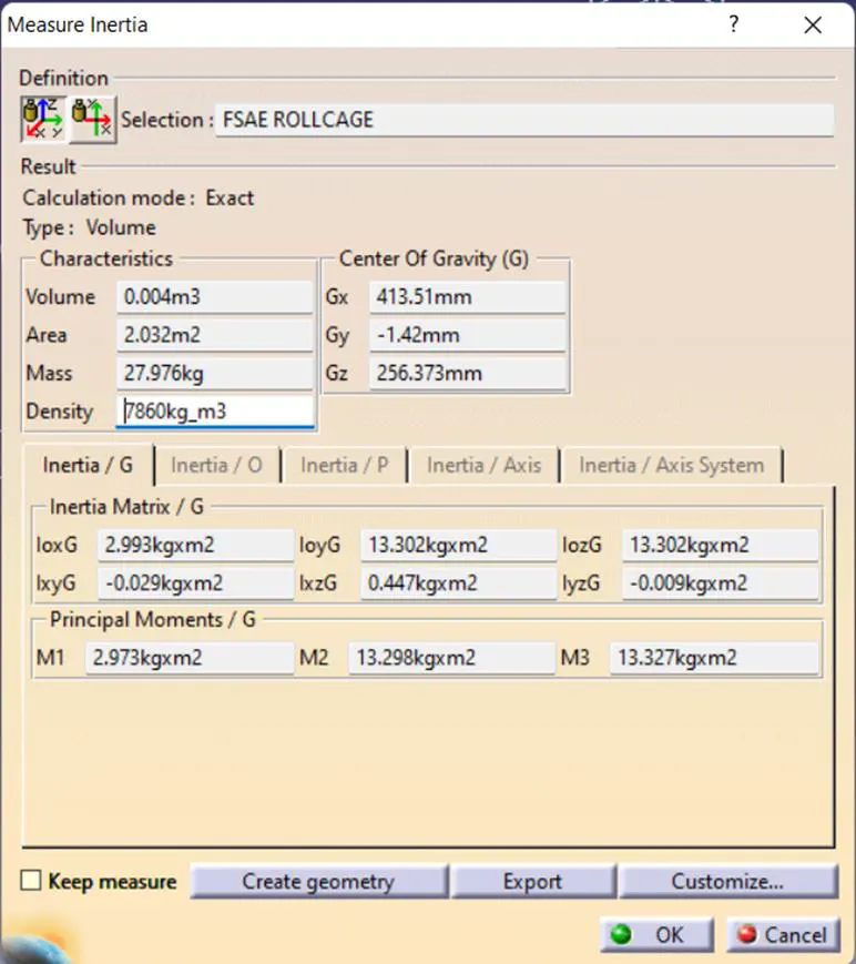
- Material – Steel
- Weight – 28kg
- Area – 2.03m²Density – 7860 kg m³
CONCLUSION:
I was able to successfully complete the CAD design of Student Formula Car chassis and in compliance with the design guidelines. The design procedure and rules mentioned in the SUPRA SAEINDIA 2020 rule book were followed while designing the chassis. The chassis was observed to be satisfying and clearing the 95th percentile male template and the cockpit templates. By working on this project, I have understood the concepts of CAD design and the design procedure and requirements to design a formula car chassis. By doing this project I have also gained knowledge about frame and structure design of a car.
REFERENCES:
[1] Waterman, Brendan J. "Design and Construction of a Space-frame Chassis." University of Western Australia. Perth (2011).
[2] Baker, Christopher Scott. "FoES Formula SAE-A space frame chassis design." (2004): 1-101.
[3] Kumar MP, Prajwal, and Vivek Muralidharan. "Design and analysis of a tubular space frame chassis of a high-performance race car." International journal of research in engineering and technology 3.02 (2014).
[4] SUPRA SAEINDIA 2020 Rulebook
[5] www.fsae.com/forums