Design of Shallow Foundation (Isolated Footings)
Design a square footing for a column size of 400x400. The compression axial load for the load combination of (1.5 DL + 1.5 LL) is 2000 KN. The safe soil bearing capacity is 150 KN/m2 at a depth of 2 metres below E.G.L. Participants are free to go for either a tapered or stepped footing. Besides the total axial load, also account for the self-weight of the footing and soil above it. Assume M25 concrete grade. Do the following checks:
- If the gross bearing pressure under the footing is within safe bearing capacity
- Provide sufficient depth and longitudinal steel for resisting bending and shear
- Sufficient anchorage for column steel into the footing
- If the bearing pressure at column-footing joint is within 0.45 times the maximum concrete compressive strength
Aim- designing a footing for a column size of 400x400.
Given Data-
Column size = 400x400
Compression axial load P = 2000 KN.
Fck = M25
Fy = Fe500
Soil bearing capacity = 150 kn/m2
Procedure –
Gross Soil Pressure And Footing area
Unfactored load with surcharge + self weight of the footing / allowable soil pressure
10% of the load is taken for self weight.
= (2000/1.5 x 1.1)/150 = 9.77m2
We assume a square footing.
Therefore,
Square root of 9.77m2 = 3.12m each side.
Net soil pressure and depth of the footing.
Factored load / actual area of footing.
2000 / (3.2 x3.2)
= Pn = 195.3 kN/m2
Assume the depth of the footing 500 mm.
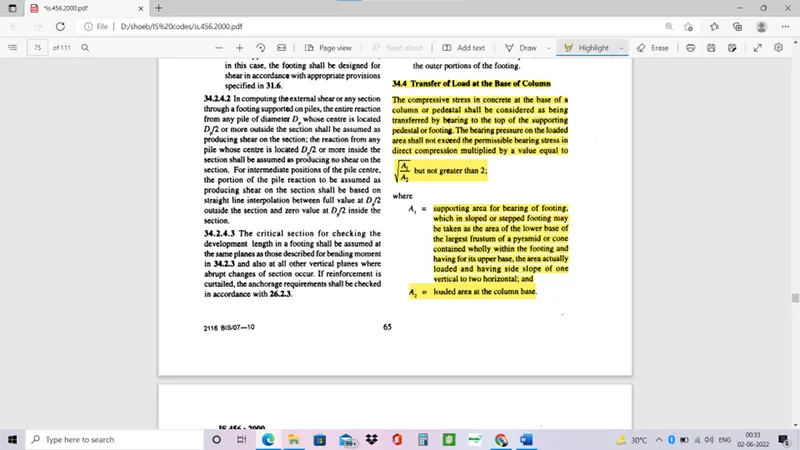
Check it for bearing stress as per IS 456-2000 clause 34.4.
Therefore,
Permissible bearing stress 0.45 x Fck = 0.45 x 25 = 11.25 N/mm2
Permissible bearing stress multiplied by the area factor of 2 = 11.25 x 2 = 22.5 N/mm2
Actual bearing stress at the column base of the footing.
2000 x 1000 / 400x 400 =12.5 N/mm2
Actual bearing stress < permissible bearing stress.
12.5 N/mm2<22.5N/mm2
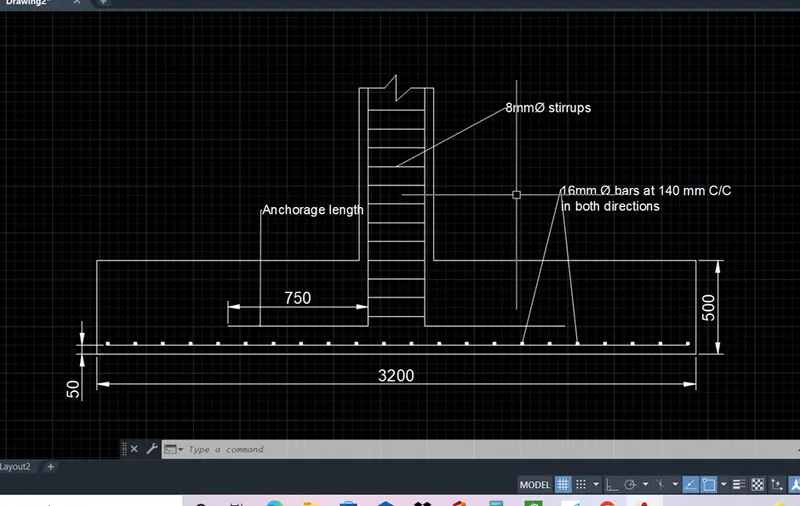
Hence 500 mm depth is okay and provide 50 mm for cover.
Effective depth = 450mm
Bending Moment and flexural reinforcement.
Bending moment due to UDL = wL2/ 2
Where,
w= net pressure into UDL.
w = 195.3 x 3.2 = 652 kN/m
= wL2 / 2
= 625 x 1.62 / 2
Mu = 800 kNm
Area of steel for 1m
Ast = 0.5x 25/ 500 x (1- √1- (4.6x 800 x 106)/ 25 x 1000 x 5002) x 1000 x500
Ast = 1450 mm2
Total Ast required = 4350mm2
No of bars
= Mu / Π/4 x d2.
= 4350 / Π/4 x 162
= 22 nos
Spacing,
S = L / Nos of bars
S = 3200 / 22
S = 145.45 mm
Therefore,
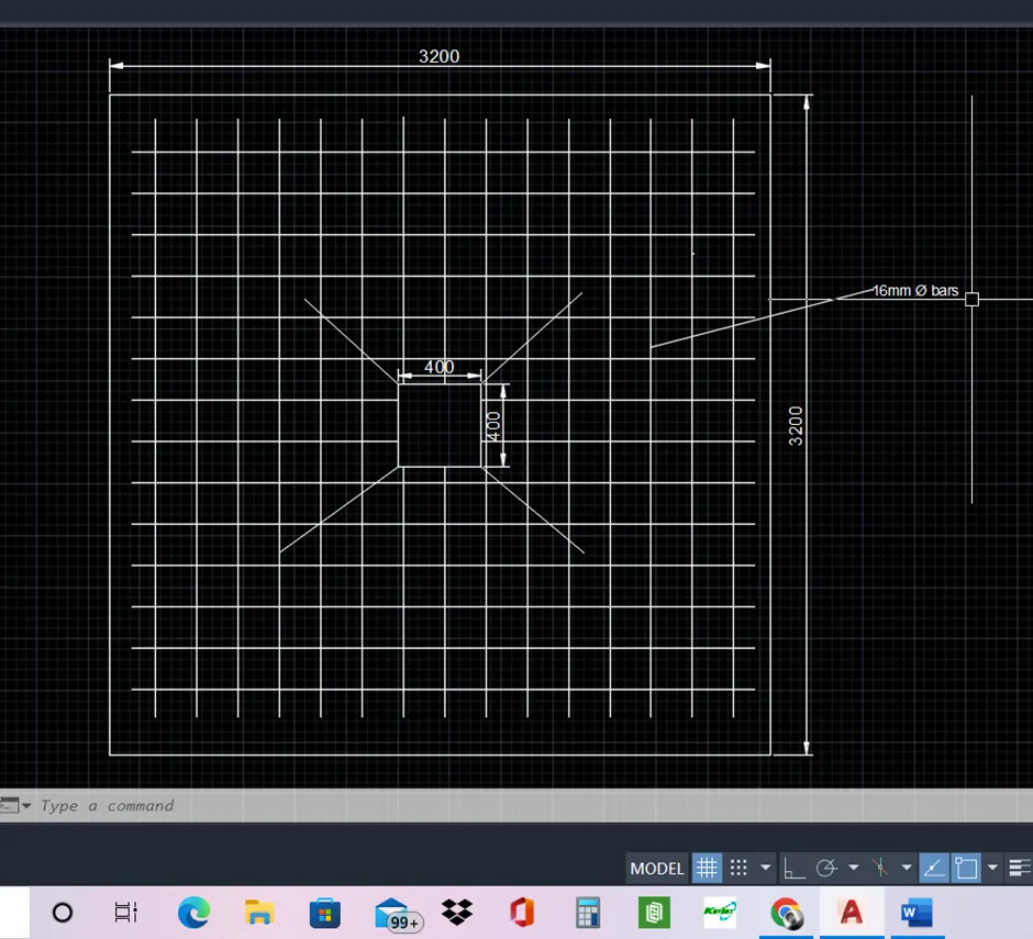
Provide 22 bars of 16mm dia at 140mm spacing.
Check for One way shear stress
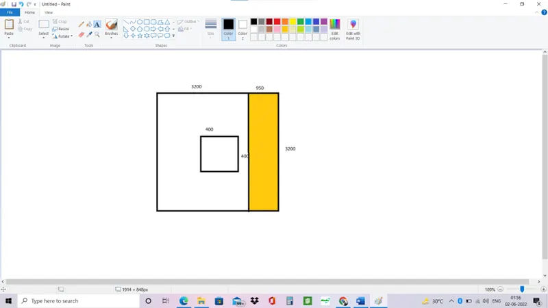
Shear force in the one way area = 0.95 x 3.2 x 195.3 kN
= 593.7 kN
Shear stress at one way cut face = tv = 593.7 x 1000 / (3200 x 450)
= 0.412 N/mm2
Shear capacity check as per IS 456-2000 table 19.
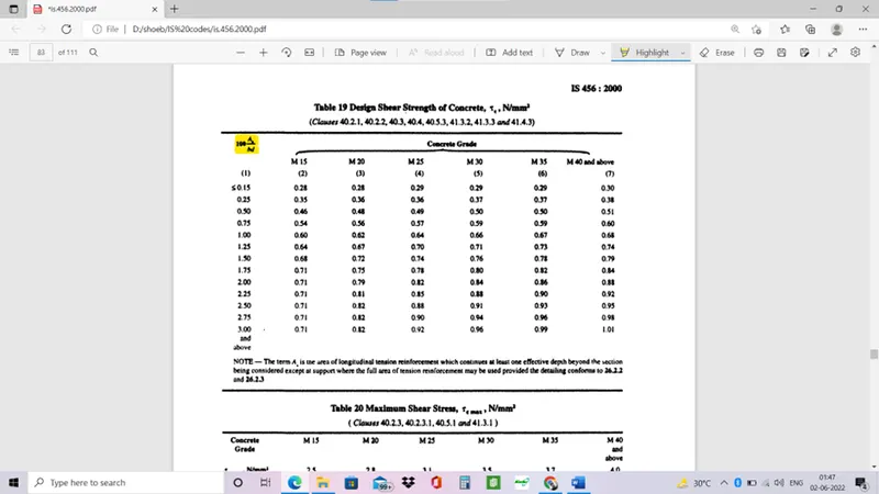
= 0.425 N/mm2
Design shear stress is less than capacity shear stress.
Hence okay.
Check for two way shear or punching shear.
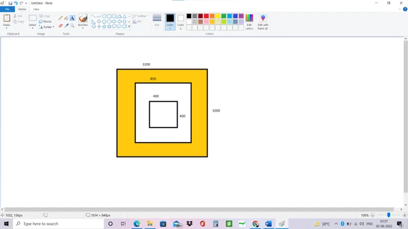
Shear force in two way
= (3.2 x 3.2) – (0.85 x 0.85) x 195.3
= 1859 kN
Design shear stress at two way cut face
Tv = 1859 x 1000 / 3450 x 450
= 1.25 N/mm2
Check for shear capacity as per IS 456-2000 cl 31.6.3.1
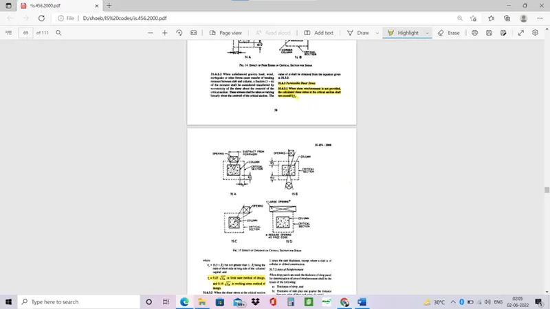
= 0.25x √fck
= 0.25x √25
= 1.25 N/mm2
Design shear stress is less than shear capacity hence okay.
RESULT-
Provide a 3.2x3.2m footing with a depth of 500 mm.
Provide reinforcement of 20mm dia bars in both directions.
Provide anchorage for column and footing at 750mm.
AutoCAD design.