Design of Shallow Foundation (Isolated Footings)
Design of Shallow Foundation (Isolated Footings)
TASK: Design a square footing for a column size of 400x400. The compression axial load for the load combination of (1.5 DL + 1.5 LL) is 2000 KN. The safe soil bearing capacity is 150 KN/m2 at a depth of 2 meters below E.G.L. Participants are free to go for either a tapered or stepped footing. Besides the total axial load, also account for the self-weight of the footing and soil above it. Assume M25 concrete grade. Do the following checks:
- If the gross bearing pressure under the footing is within the safe bearing capacity
- Provide sufficient depth and longitudinal steel for resisting bending and shear
- Sufficient anchorage for column steel into the footing
- If the bearing pressure at the column-footing joint is within 0.45 times the maximum concrete compressive strength
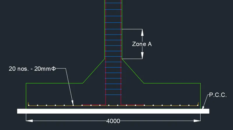
Provide a simple sketch showing the size of the footing, maximum and minimum depth of the section, flexural reinforcement in both directions, and anchorage of column steel.
AIM:
To manually calculate the spread footing dimensions and reinforcement details with respect to limit state design of soil and structure.
INTRODUCTION:
- Footings and other foundation units transfer loads from the structure to the soil or rock supporting the structure.
- The distribution of soil pressure under a footing is a function of the type of soil and the relative rigidity of the soil and the foundation pad.
- The most common type of footings used are
- Strip or wall footing
- Spread footing
- Stepped footing
- Tapered footing
- Pile cap
- Combined footing
- Mat or raft footing
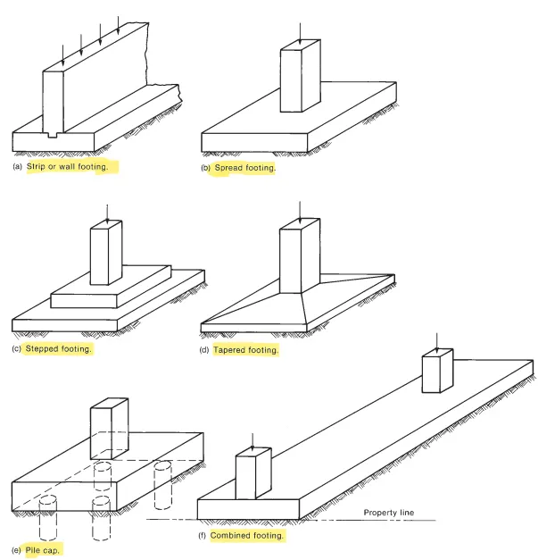
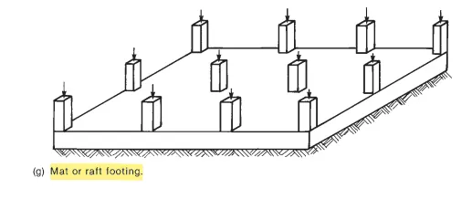
- This project is dealing with isolated footing for a column or a spread footing.
PROCEDURE:
Data Given:
- Column Size = 400mm X 400mm
- Compression axial load = 2000 KN
- Safe soil bearing capacity = 150 KN/`m^2`
- Compressive Strength `f_(ck)`= M25
- depth = 2 metres below E.G.L
- Soil depth = 20 KN/cu.m
- RCC density = 25 KN/cu.m
Steps Involved in design of Square Footing
- Determine the size of Footing
- Net Upward Pressure
- Depth of footing on the basis of B.M.
- Area of Reinforcement
- Check for One way Shear
- Check for Two way Shear
Solution:
Step 1: Size of the footing
Assume the self effect of footing equal to 10% of the superimposed load.
`W_d= 10% of 2000`
`=0.1xx2000=200KN`
Now total load,`W=W_L+ W_d`
`=2000+200=2200 KN`
Area of Footing (A) = W / SBC
`= 2200/150=14.67m^2`
Take B =`sqrt A=sqrt14.67=3.82`
Hence, provide the size of Square footing is 4m X 4m
The area of footing is `16m^2`
Step 2: Net Upward Pressure (`P_o`)
`P_o`= (W X 1.5)/ Size of Footing
`=(2200xx1.5)/(4xx4)`
`P_o =206.25(KN)/m^2`
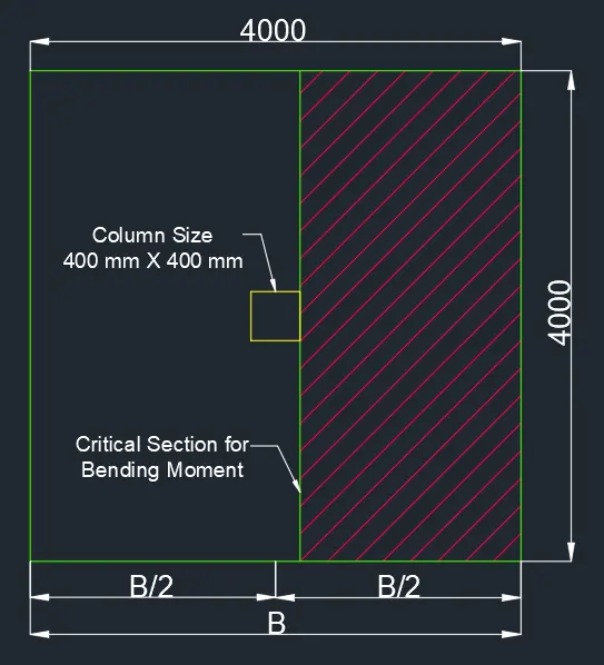
Step 3: Depth of footing on the basis of B.M.
The maximum bending moment at the face of the columnand it is given by, `M=P_o *(B/8) *(B-b)^2`
`M=206.25*(4/8)*(4-0.4)^2`
`M= 1336.5 (KN)/m`
To get the ultimate moment, we need to calculate Mu
Mu = 1.5 X Moment
Here, 1.5 is Factor of safety.
Ultimate Moment `[M_u]=1.5M`
`=1.5xx1336.5`
`M_u=2004.75(KN)/m`
Now, Calculate the Depth of Footting (D):
`M_u=0.138f_(ck)Bd^2`
`2004.75=0.138xx25xx4000xxd^2`
`d=sqrt[(2004.75xx10^6)/(0.138xx25xx4000)]`
`d=381.14`
By the thumb rule, take 2.5 times higher value of d for shear ckeck.
`d=381.14xx2.5=952.85`
`D=d+50`
`=952.85+50=1002.85~~1003 mm`
Step 4: Area of Reinforcement
`A_(st)=(0.5f_(ck))/f_y``[1-sqrt(1-(4.6M_u)/(f_(ck)Bd^2))]Bd`
`=(0.5xx25)/415[1-sqrt(1-(4.6xx2004.75xx10^6) /(25xx4000xx953^2))]xx4000xx953`
`A_(st)=5985.3mm^2`
Now we have to find the % of the reinforcement.
`P=A_(st)/(Bd)xx100`
`=5985.3/(4000xx953)xx100=0.157%`
We have to find the No. of bars required for the reinforcement.
Assume 20mm dia of bar
Area of bar= `pi/4xx20^2=314.5 mm^2`
`A_(st)=5985.3mm^2`
No. of bars =`5985.3/314.5=20`
Hence, provide 20 nos of 20mm bars.
Spacing betwwen the bars = B/ no. of bars
`=4000/20=200mm`
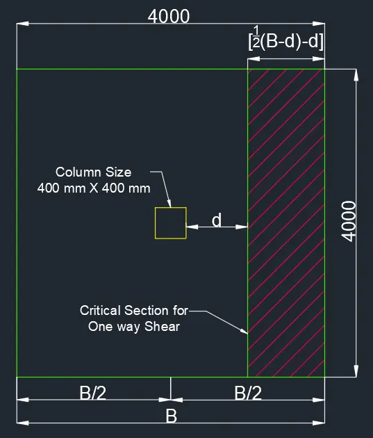
Step 5: Check for One-way Shear
For one-way shear, critical section is located at a distance "d" from the face of column.
Now, Shear Force (V) = `P_oB{1/2(B-b)-d}`
`=206.25xx4{1/2(4-0.4)-0.952}=699.6KN`
Ultimate Shear Force(`V_u`) = `1.5xxV`
`=1.5xx699.6=1049.4KN`
As per Page no-72 of IS: 456-2000 Nominal Shear Stress `tau_v=V_u/(Bd)`
`=(1049.4xx10^3)/(4000xx953)=0.27N/(mm^2)`
As per Page no-72 of IS: 456-2000 Design shear strength of concrete `tau_c'=tau_cK`
K = 1
`tau_c`for 0.157% of P is 0.28`N/(mm^2)`
`tau_c=0.28N/(mm^2)`
Then `tau_v`< `tau_c`. Hence OK.
Now `tau_v`< `tau_c'`
`V_u/(Bd)=K*tau_c`
`d=V_u/(B*K*tau_c)`
`d=(1049.4xx10^3)/(4000xx1xx0.28)=937mm`
d provided = 953mm > 937mm
Hence OK for One-way Shear.
Step 6: Check for Two-way Shear (Punching Shear)
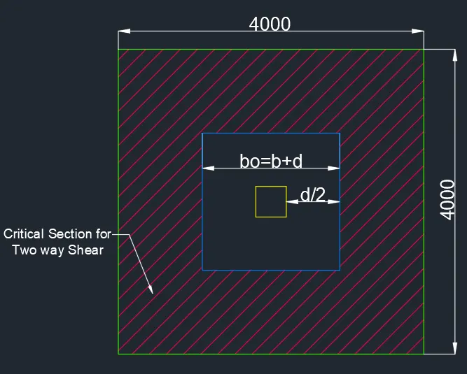
For Two-way Shear, the section lies at a distance d/2 from the column face all around.
The width = `b_o=b+d`
`=400+953=1353 mm`
Now the net shear force acting on the perimeter
`F=P_o[B^2-b_o^2]`
`=P_o[B^2-(b+d)^2]`
`=206.25[4-(1.35)^2]=449.11 KN`
Now Ultimate Shear Force,`F_u=1.5xxF`
`=1.5xx449.11=673.67KN`
Now, From Page no-57, Clause no-31.6.2 of IS: 456-2000
`tau_v=F_u/(4b_od)`
`tau_v=(673.67xx10^3)/(4xx1353xx953)=0.13N/(mm^2`
Now, From Page no-58 of IS: 456-2000, Permissible Shear Stress (`K_s tau_c`)
Here `K_s=1`(Max.)
`tau_c=0.25sqrt(f_(ck))`
`=0.25sqrt25=1.25`
`K_s tau_c=1xx1.25=1.25`
`tau_v`< `tau_c`
Hence, Safe in Two-way Shear.
RESULT:
The required square footing is designed and detailed as per the given data. All the required limit state criteria are OK and verified. The results of each drawing drawn in AutoCAD are attached.