Design of Shallow Foundation (Isolated Footings)
AIM
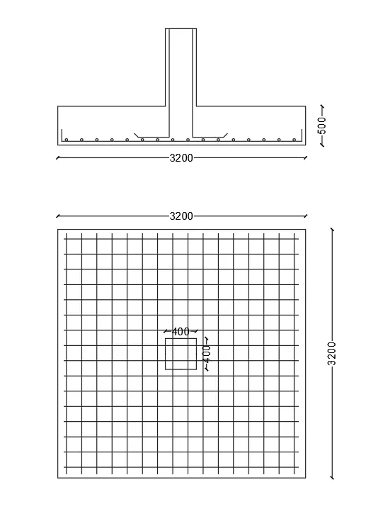
Design a square footing for a column size of 400x400. The compression axial load for the load combination of (1.5 DL + 1.5 LL) is 2000 KN. The safe soil bearing capacity is 150 KN/m2 at a depth of 2 meter below E.G.L. Participants are free to go for either a tapered or stepped footing. Besides the total axial load, also account for the self-weight of the footing and soil above it. Assume M25 concrete grade. Do the following checks:
- If the gross bearing pressure under the footing is within safe bearing capacity
- Provide sufficient depth and longitudinal steel for resisting bending and shear
- Sufficient anchorage for column steel into the footing
- If the bearing pressure at column-footing joint is within 0.45 times the maximum concrete compressive strength
INTRODUCTION
Here we are designing a square footing for a column of 400x400 size
The reinforcement detail drawing is drawn using AutoCAD
Code used 1S 456-2000
PROCEDURE
Step 1:Calculation of the size of the footing
Load acting on the footing=unfactored load on column + self-weight of footing/allowable soil pressure
=(2000/1.5)+2000*0.1=1533 KN
Area of footing=(Load acting on the footing/safe bearing capacity)
=1533/150 =10.22 mm^2
Assume square footing
Area of footing =A^2
A=square root of 10.22
A=3.19
Length=width =3.20m
Step 2:Calculation of Net soil Pressure
Net soil Pressure=Factored load/Area of footing
=2000/(3.2*3.2)
=195.3 KN/m^2
Step 3:Determination of initial depth of footing
Assuming the depth of footing to be 500 mm and checking it for bearing stress as per IS 456:2000 clause 34.4
As per the IS 456:2000 clause 34.4,
√(footing base bearing area/loaded area at the column base)≤2
=√(2400X2400)/(400X400)=6 ,as it is greater than 2 ,we cannot use the value
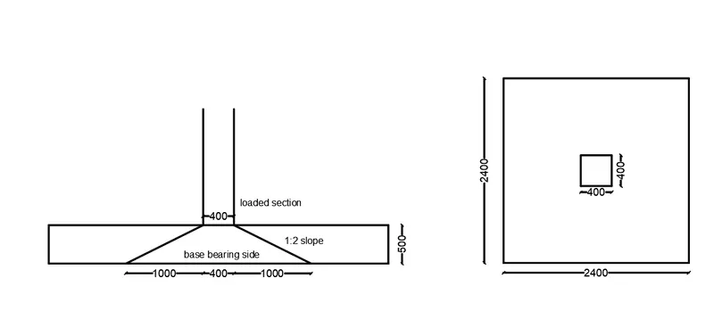
Permissible bearing stress=0.45XFck=0.45X25=11.25N/mm^2
Permissible bearing stress multiplied by area factor=11.25X2=22.50N/mm^2
The actual bearing stress at the column base=(2000X1000/400X400)=12.5N/mm^2
Actual bearing stress is lesser than the permissible bearing stress,12.5<22.5N/mmm^2, Hence,ok.
We can proceed with 500mm depth for further design checks.
If we consider 50 mm as cover,then the effective depth can be =d=450mm.
Step -4:Determination of Flexural Reinforcement
Conversion of net pressure into uniformly distributed load=195.3*3.2=624.96
=625KN/m
Bending moment due to udl over a cantilever section=(W*L^2)/2=(625 X 1.6*1.6)/2
=800 KNm
Reinforcement calculation as per IS 456:2000, Annex G
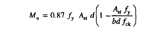
Assume fy = 500N/mm^2
Then the Ast =4350mm^2
Provide 16 mm dia bars at 125 mm c/c spacing
Number of bars=3200/125=25.6
Provide 26 bar
Ast provided =26*201=5226
Step -5:Check for One Way Shear
Critical setion d from face of column
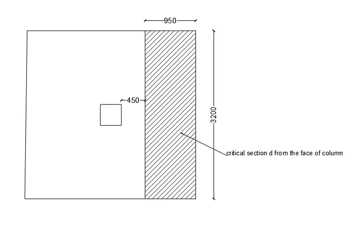
Shear force in the one way Shear shaded area=195.3 X 0.95 X 3.2=593.7KN
Design shear stress at one way cut face,
τv = Vu/Bd=593.7x1000/3200X450=0.412 N/mm^2
Shear stress capacity of the section as per IS 456:2000,Table 19
We arrived the Tc value as =0.425 N/mm2
Since,the design shear stress is less than the shear capacity, hence,ok.
Step -5:Check for Two Way Shear
Critical setion d/2 from face of column
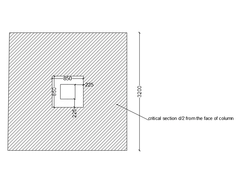
Shear force in the Two way Shear shaded area=(3.2X3.2)-(0.85x0.85)x195.3=1859 KN
Design shear stress at Two way cut face,
τv = Vu/Bd=1859X1000/3400x450=1.215 N/mm^2
Shear stress capacity of section as per is 456:2000 clause 31.6.3.1
0.25√Fck=0.25*25=1.25 N/mm^2
The design shear stress is less than the shear capacity, hence,ok
RESULTS