DESIGN OF BUTTERFLY VALVE IN NX CAD WITH THE APPLICATION OF GD&T - ASME 14.5 2009
AIM – DESIGN OF BUTTERFLY VALVE IN NX CAD WITH THE APPLICATION OF GD&T – ASMEY14.5 2009
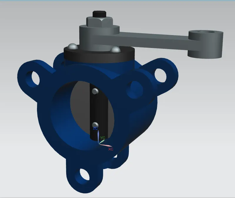
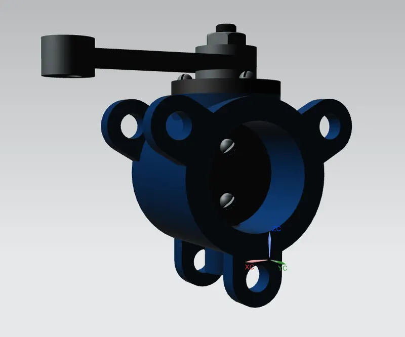
OBJECTIVE- The main objective of this project is to model different parts of Butterfly valve and assemble with the applications of GD&T (drafting).
SOFTWARE USED- NX CAD 12.0 (NX, formerly known as "unigraphics", is an advanced high-end CAD/CAM/CAE, which has been owned since 2007 by Siemens PLM Software. In 2000, Unigraphics purchased SDRC I-DEAS and began an effort to integrate aspects of both software packages into a single product which became Unigraphics NX or NX.)
INTRODUCTION-
BUTTERFLY VALVE –
- It is a valve that isolates or regulates the flow of a fluid/gas . it consists of various parts such as body, shaft, lever, arm, retainer, disc, nut and screws.
- In butterfly valve the lever is connected with the shaft and shaft is connected with the disc and fitted into the body and top closed by retainer where screws are bolted .
- The disc angle can be changed while using lever the angle of disc determines the restrictions.
- Butterfly valves are favoured because of their low cost and lighter weight. The disc is always present in flow therefore pressure drops is induced regardless of the valve positions.
- This valve controls the starting, stopping and regulating flows.
- Large flow and low pressure applications.
- Good for slurries.
- Maintainence cost is low.
GD&T-
- GD&T, short for Geometric Dimensioning and Tolerancing, is a system for defining and communicating design intent and engineering tolerances that helps engineers and manufacturers optimally control variations in manufacturing processes.
Feature Control frame
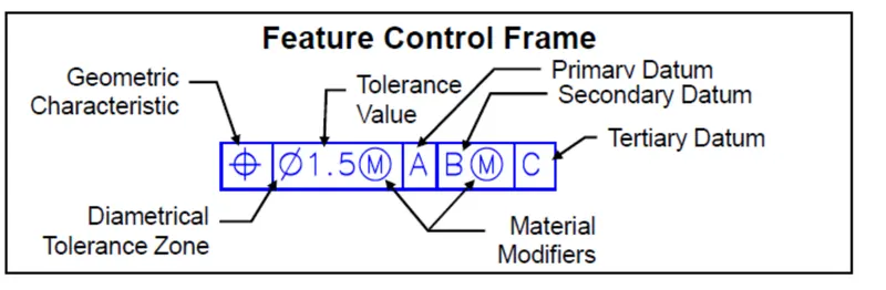
- it is a set of boxes define the operator how to manufacture the parts.
- Feature control frame is generally the language of geometric dimension and tolerance.
- maximum boxes a feature control frame can have is 5.
- minimum boxes a feature control frame can have is 2.
FEATURE CONTROL FRAME VARIOUS TERMS
- Geometric characterstics- genrally they are in the very first box of fcf. it tells us about what type of tolerance we need to hold. There are 14 types of geometric characterstics i.e. straightness, flatness, circularity, cylindricity, profile of a line, profile of surface, angularity, perpendicularity, parallelism, positions, concentricity, symmetry, circular runout, total runout.
- Modifier- material modifier is known as bonus tolerance which defines the tolerance.
- DATUM- datum is a plane, a straight line, or a point that is used as a reference when processing a material or measuring the dimensions of a target.
- Tolerance zone shape- It generally come in picture when we given tolerance to hole or pin.
- Tolerance- it determine the amount of tolerance we need to hold . these are generally in millimetres.
DESIGN METHODOLOGY
For this entire design ,drafting , assembly using the parametric cad software , siemens nx . First each part will be individually designed and 2 d drafting will be done with the applications of GD&T and then the final assembly will be done and drafted.
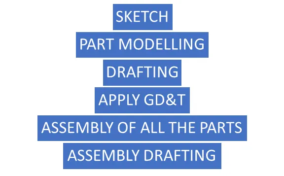
THE PART MODELLING OF BUTTERFLY VALVE WILL CONSIST OF –
- BODY
- SHAFT
- DISC
- LEVER
- REATINER
- SCREWS
- HEXAGONAL NUT
For modelling of above parts commands were used such as-
- SKETCH- it is used to create a 2D drawing which is later used to form 3D model.
- EXTRUDE- it extrudes the sketch or selected sketch contours in one or two directions to create a solid feature.
- HOLE- a hole feature is used to creates holes on the model.
- UNITE- it function is to convert two or more solid bodies into one solid body.
- REVOLVE- it revolves a sketch or selected sketch contours around an axis to create a solid feature.
- CHAMFER-it is used to connect two adjacent faces using an inclined line.
PART CREATION- As in most of the CAD packages , NX also requires base sketch for the part to be designed. The sketch can be first drawn and the feature can be applied later. Also, the sketch created within the command all the parts for this butterfly valve created in the modelling environment of NX CAD.
ASSEMBLY CREATION- assembly creation in NX is a very simple method as it allows to preselect the joints and to move the component in the assembly process as per design intent . alignment and touch command is generally used.
APPLICATIONS OF GD&T- after each part is designed under the application , modelling in nx , the drafting application is choosed to create a drawing for individual parts. After the drawing is created using the required drawing views, proper GD&T is applied as per the requirements of various parts. Applications of GD$T in NX is a very simple and effective process because it allows applying any kind of GD&T with few clicks. The feature control frame and datums can be applied easily as per the requirement of following standards.
Manufactured items differ in size and dimensions from the original CAD model due to variations in the manufacturing processes. To optimally control and communicate these variations, engineers and manufacturers use a symbolic language called GD&T, short for Geometric Dimensioning and Tolerancing.
GD&T tells manufacturing partners and inspectors the allowable variation within the product assembly and standardizes how that variation is measured.
This guide walks through the GD&T system for streamlining communication about the design in both traditional and digital manufacturing.
Limitations of Tolerancing Before GD&T
Before GD&T, manufacturing features were specified by X-Y areas. For example, when drilling a mounting hole, the hole had to be within a specified X-Y area.
An accurate tolerancing specification, however, would define the position of the hole in relation to the intended position, the accepted area being a circle. X-Y tolerancing leaves a zone in which inspection would have produced a false negative because while the hole is not within the X-Y square, it would fall within the circumscribed circle.
Stanley Parker, an engineer who was developing naval weapons during World War II, noticed this failure in 1940. Driven by the need for cost-effective manufacturing and meeting deadlines, he worked out a new system through several publications. Once proven as a better operational method, the new system became a military standard in the 1950s.
Currently, the GD&T standard is defined by the American Society of Mechanical Engineers (ASME Y14.5-2018) for the USA and ISO 1101-2017 for the rest of the world. It concerns mostly the overall geometry of the product, while other standards describe specific features such as surface roughness, texture, and screw threads.
MODELLING AND DRAFTING OF BUTTERFLY VALVE PARTS
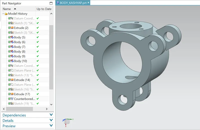
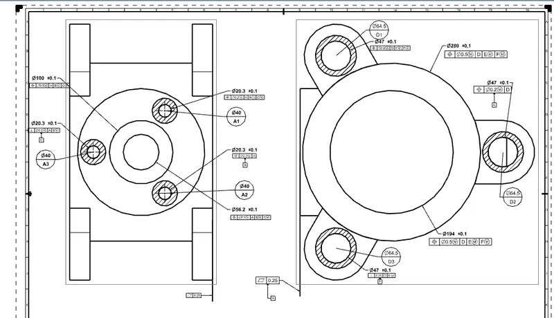
- BODY- It is the main components of butterfly valve. The body connects of two pipes on its two sides and it regulates flow. For creating 3D modelling basics command like sketch, extrude, holes and pattern feature are used. For the application of GD&T on the parts body , it is better to apply it once the parts are assembled it because will be connected to two pipes once assembly is completed.
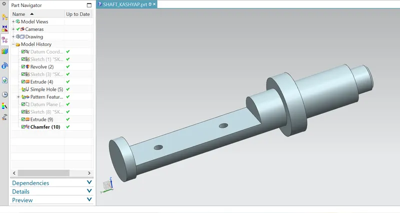
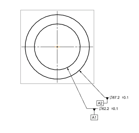
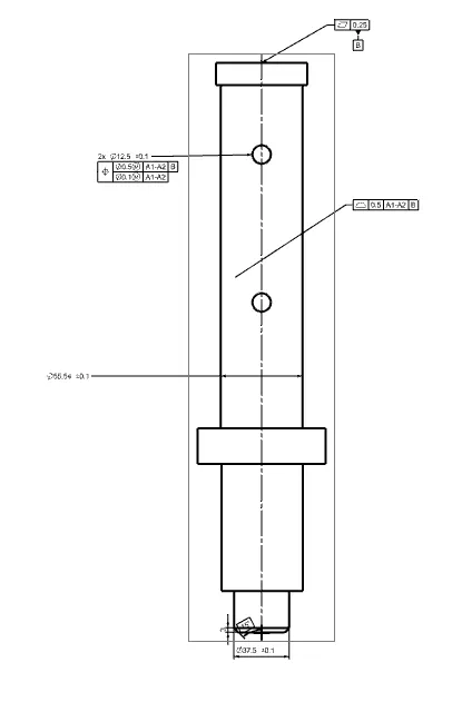
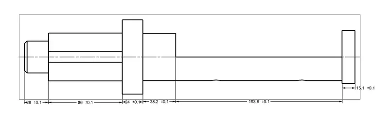
- SHAFT- it is an important component of a butterfly valve . it inserts perpendicular into the body of the valve . it hold the disc inside the body with the help of screws.for creating 3D model of shaft sketch , revolve , extrude and chamfer is used. After the part creation is complete drafting is done . for this position tolerance should be given to the holes which hold the disc. A profile of the surface should be applied to the surface where the disc sits and the position tolerance for cylindrical body of the shaft with respect to defined datums. Composite position tolerance is applied in case of disc positioning holes as it repeats creating pattern.
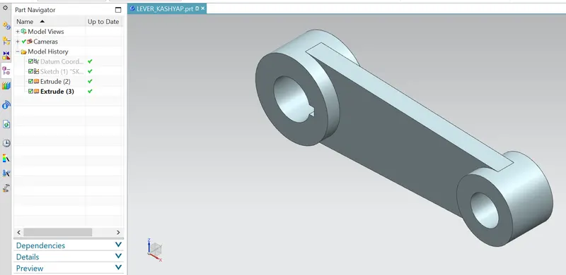
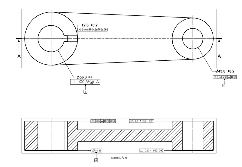
- LEVER- a lever is handle that is used to rotate in order to start and stop of flow. When the lever is rotated the shaft which is connected with the disc also rotates with respect to lever. For the application of GD&T on lever different datums are defined. position tolerance is applied to the proper holes after the perpendicular tolerance is applied to one of the hole. Profile tolerance are provided to the surface which comes to contact with other parts as per requirements.
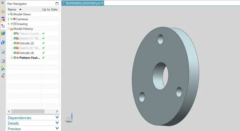
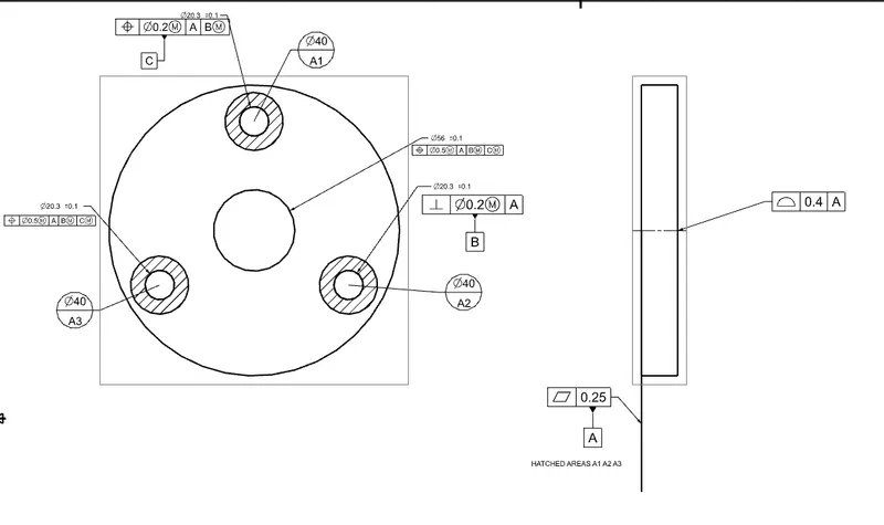
- RETAINER-This parts helps to retain or fix the shaft with the body of the butterfly valve. It prevents the shaft from coming out of the body and position the proper functioning of the disc inside the body. perpendicular and position tolerance are applied in the DOF of the retainer in position. A profile tolerance is also applied to control the upper surface of retainer.
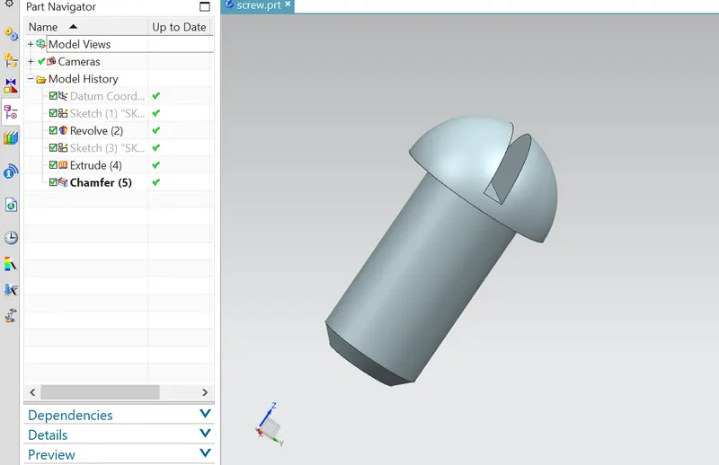
- SCREW-It helps to fix the disc with the shaft of butterfly valve.
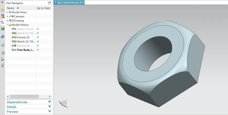
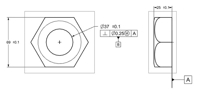
- HEX NUT-It is the last part that helps to fix the lever in position with the stem . it allows to keep in position .The primary datum is defined on the surface which comes in contact with lever. Perpendicular tolerance is applied to the hole or the thread and is defined as datumB. Size tolerance is also applied to thickness of nut.
ASSEMBLY-
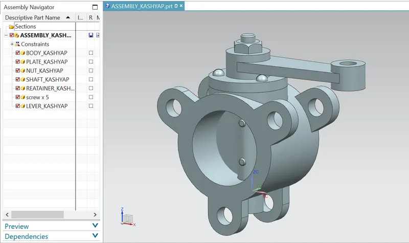
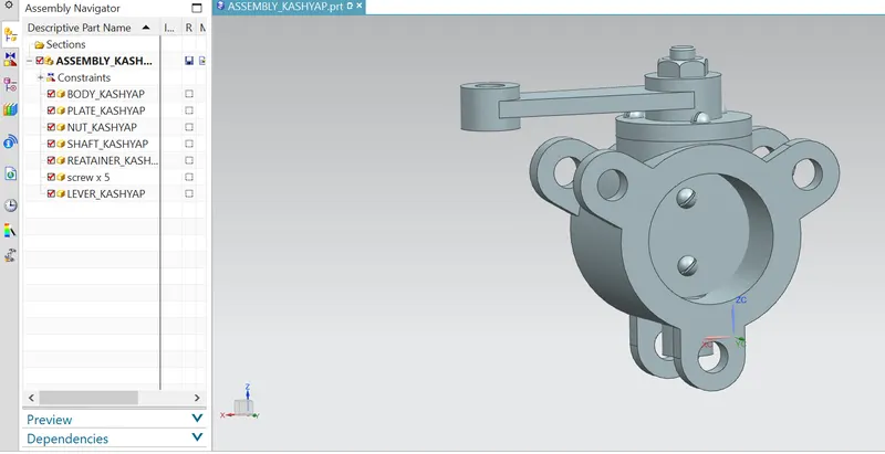
First body is placed in position mating other parts to it and then shaft and disc are joined together with screw in place . the retainer plate is then mated with the body and screws are used to fix them. Finally lever is mated to the shaft in position that is fixed after the nut is mated with shaft.
DRAFTING -
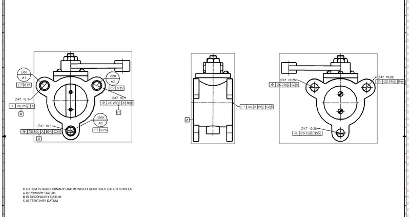
There are three holes on both sides which will come with contact with the two pipes. The primary datum is defined as the surface containing three holes with the application of datum target . Perpendicular and position tolerance are given to other datums i.e secondary and tertiary. There is also a sub datum D with respect to the datum A . Flatness tolerance is applied to the primary datum whereas profile tolerance is applied to the other side of body.
CONCLUSION-Different parts of butterfly valve ae individually created and drafted with GD&T application and also assembled using NX CAD.