Design of backdoor
Aim:
To design the backdoor /Tailgate of the Car with the given styling Surface skin data and to develop necessary reinforcements and mountings.
Back Door /Tailgate/Lid:
The door or opening of a cargo area may be hinged at the top, side, or bottom.
If the door is hinged at the bottom, it is called a tailgate, particularly in the United States. They are used on station wagons and pickup trucks, as well as on some sport utility vehicles (SUV). Traditional drop-down station wagon and pickup tailgates can also serve as a mount for a workbench.
Traditional U.S. station wagons included a roll-down window retracting into the tailgate to load small items or to allow the tailgate to be opened down on its bottom-mounted hinges. Because of the potential for carbon-monoxide fumes, the tailgate window on station wagons should be closed whenever the engine is running.
Two-way station wagon tailgates may be hinged at the side and the bottom so they can be opened sideways like a regular door, or drop downwards as load platform extenders. They are designed with special handle for opening in the selected direction on special hinges after the window is lowered.
A three-way design that was also used by Ford allows for the tailgate to be opened like a door with the window up.
General Motors developed a clam shell style "disappearing" design where the rear window rolls up into the roof and the tailgate slides down and beneath the load floor.
If the door is hinged at the top it is termed a hatch, and is used on a hatchback. A bottom opening door is now common on SUVs.
The trunk lid (in the U.S. automotive industry sometimes also called decklid or deck lid) is the cover that allows access to the main storage or luggage compartment. Hinges allow the lid to be raised. Devices such as a manually positioned prop rod can keep the panel up in the open position. Counterbalancing torsion or other springs can also be used to help elevate and hold open the trunk lid. On cars with their trunk in the rear, lids sometimes incorporate a center-mounted third brake light. A rear lid may also have a decorative air spoiler. On many modern cars, the trunk lids can be unlocked with the car's key fob.
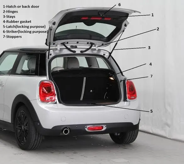

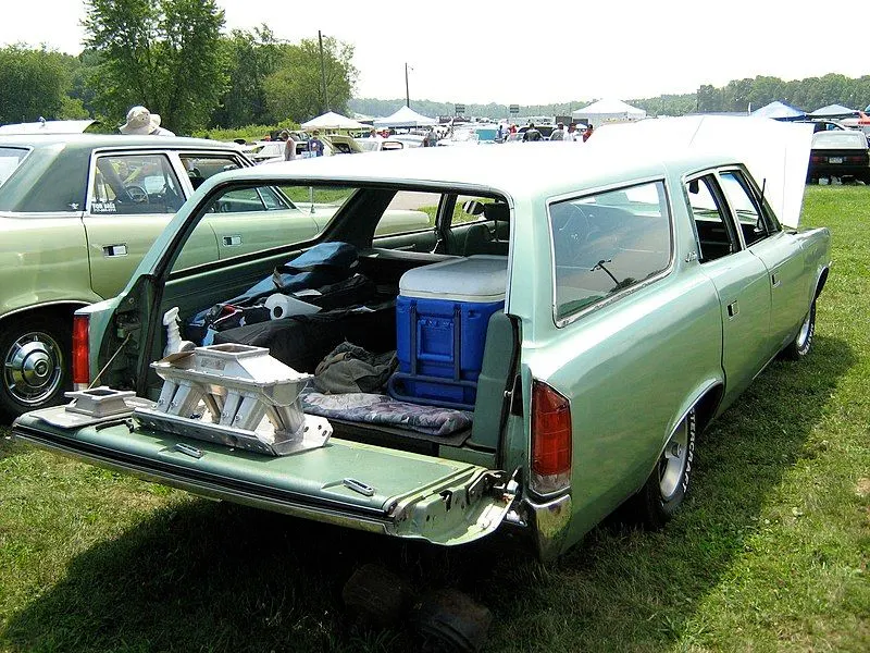
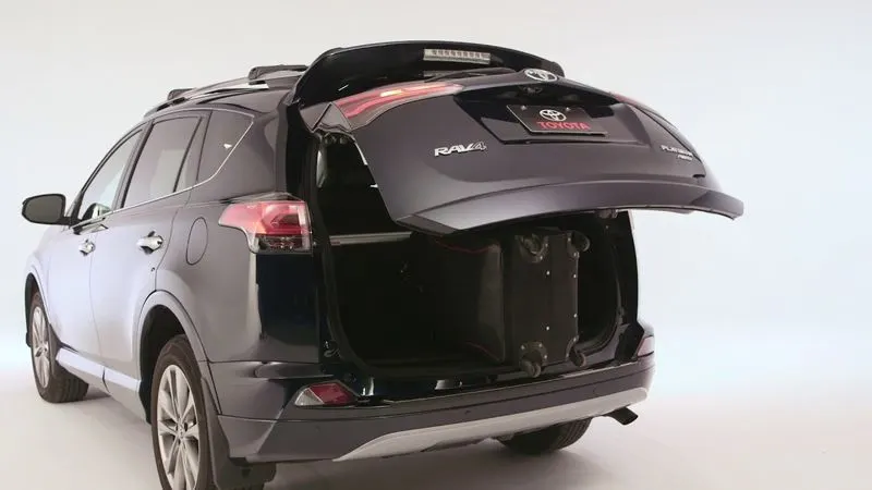
Components of a Tailgate /Back Door:
- Outer Panel upper
- Outer Panel Lower
- Inner panel
Design Considerations of the Backdoor:
- Rear Visibility criteria
- Rear Crash Regulations
- Loading and Abuse Cases
- Luggage or Boot Space Volume
- Ease of Manufacturability
Loading Cases:
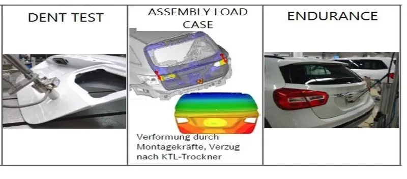
Bending test, Torsion test, Abuse test, Dent test, Assembly load tent and Endurance test are carried out on the back door to check the Behaviour and Strength.
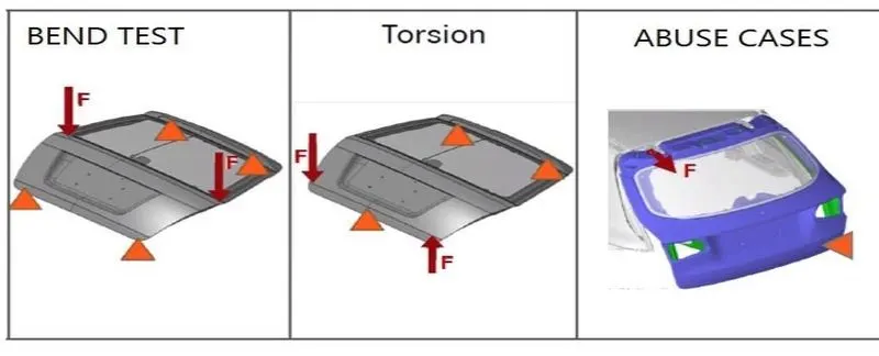
Design of Back door:
The design stage of the backdoor/tailgate begins with the given styling surface skin data which is also called the Class - A Surface. This Class - A Surface Consists of two parts of the backdoor, one: the upper outer panel and other: the lower outer panel. These two should needs to be separated into two independent part models for the easy referencing.
Once the upper and lower panels are saved in their respective part files, the next stage of designing is carried out. Since, back door is not a single component and consist of multiple parts and are assembled together as one so an assembly file is created and the parts are created within the assembly file. Once the part files are added in the queue of the assembly file the actual designing is carried out.
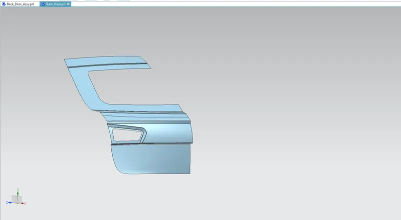
As the given Class - A surface may Contain discontinuities or irregularities it is safer to repair it before taking the referencing from it.
Repairing of Class- A Surface:
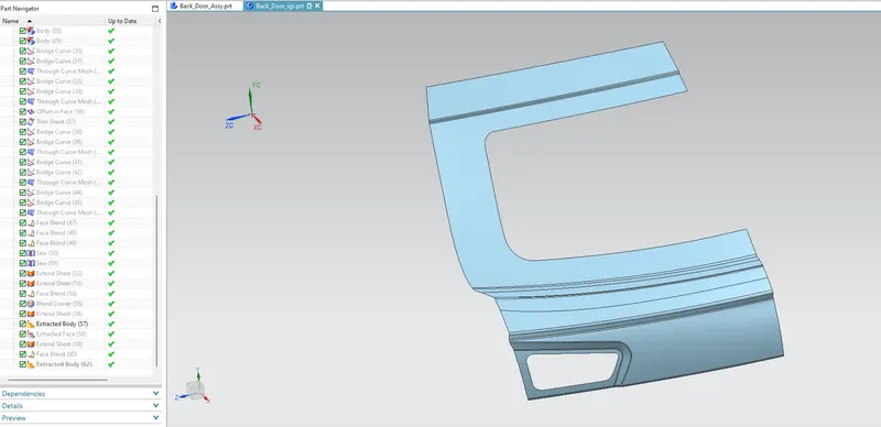
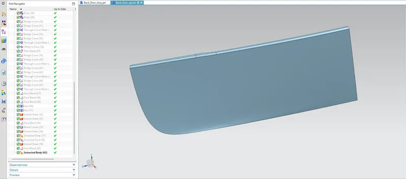
Each and every face of the Class – A surface data is checked thoroughly for irregularities and the surfaces that are bad are removed and a new surface is created in between the good and regular surfaces. These steps are continued until the surface of the whole model becomes good and fit for referencing.
Once the repairing of the Class – A surface they are separated into upper and lower panels for the referencing purpose and the separated bodies from the model is copied to their respective models in their corresponding file names.
Design of Inner Panel:
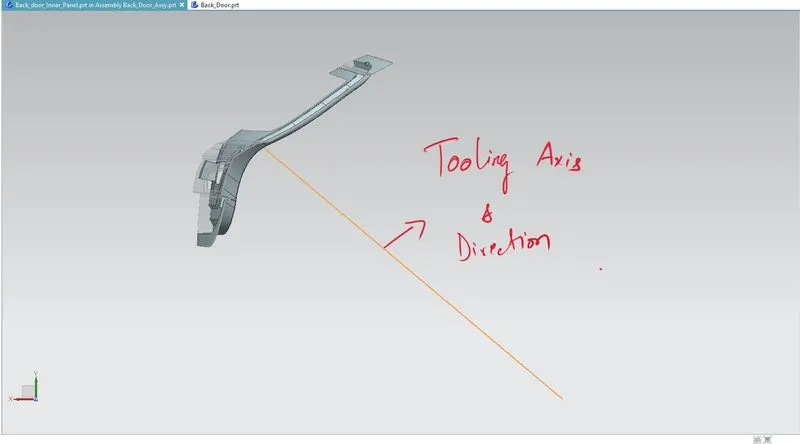
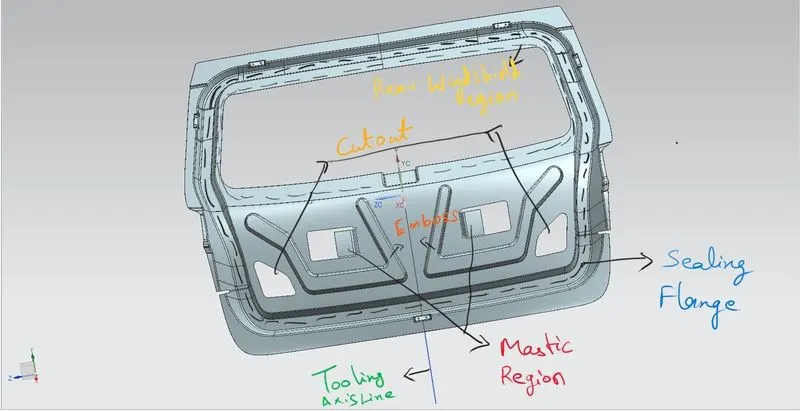
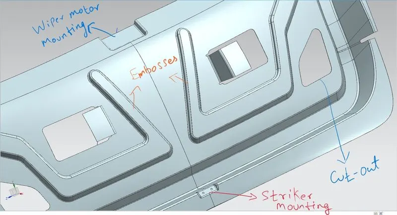
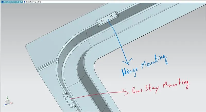
At first the reference surfaces of the upper and lower panels are taken from the respective part to the created inner panel part file and the design of the inner panel is started. First, the inner panel’s surface is offset as per the master section reference and the gaps requirements and the Tooling direction is created because it would be the direction for manufacturing and production. And the sealing flange is created by creating another offset and joining them with smooth surface transition. And, the rear windshield glass placement area is designed by creating other offset and joining with the sealing flange’s surface. Then, the inner panel is closed with another smooth surface and all the gaps and irregularities are enclosed with small smooth surfaces at all sides to ensure a good surface at all sides. After that, embosses and cutouts are given to provide extra strength and accessibility for mounting other back door commodities, and since the cavity is big in the center portion in between the inner panel and the outer panel it cannot be joined physically and also cannot be left as it is because it would rattle or vibrate while the vehicle is moving and running and also reduces the strength of it. Hence, mastics are introduced in between the panels and the mastic mounting region is created with the necessary clearances for the mastics to get seated firmly and hold the panels in place. Once the inner panel gets a final shape hinge mountings and gas stay mountings are created and are joined with the inner panel then it is mirrored about the center axis/plane and are joined and the striker and wiper motor mounting are added and joined and thickened.
Tooling Axis:
Inner Panel:
Design of Reinforcements:
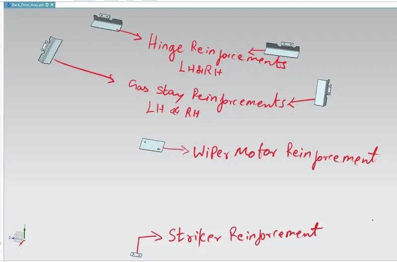
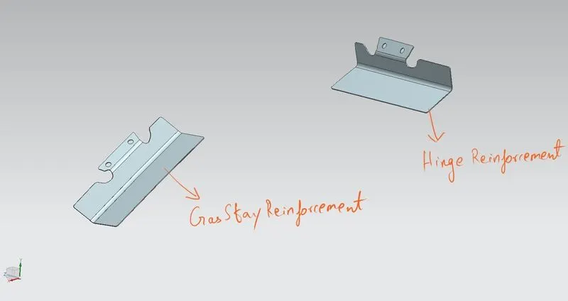
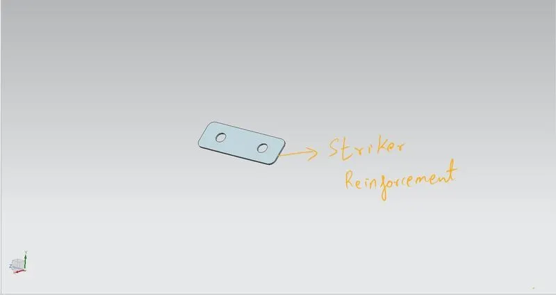
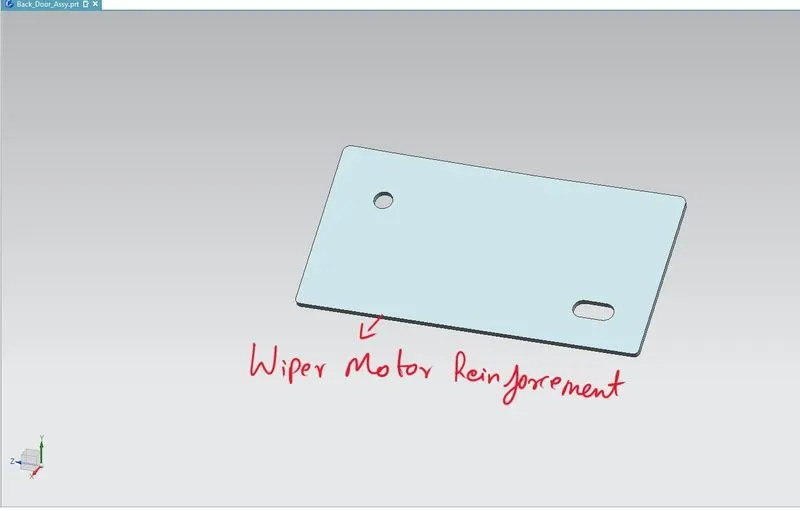
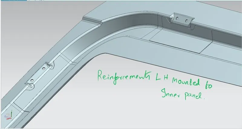
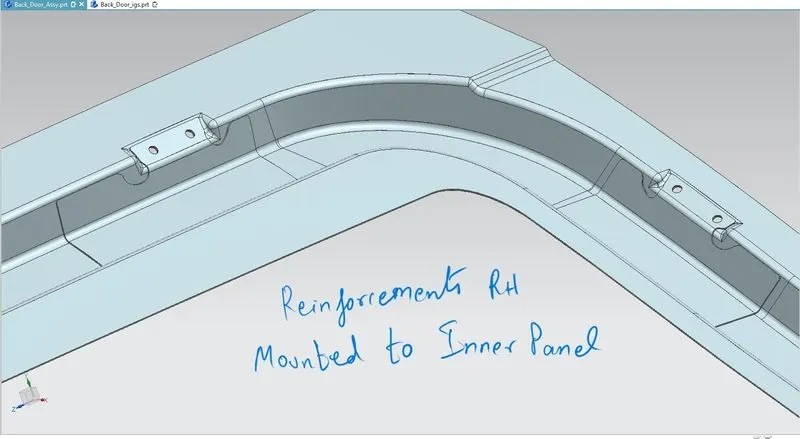
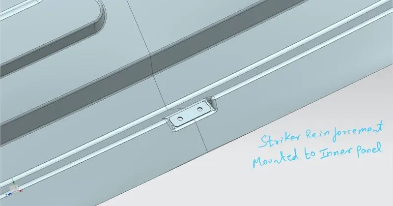
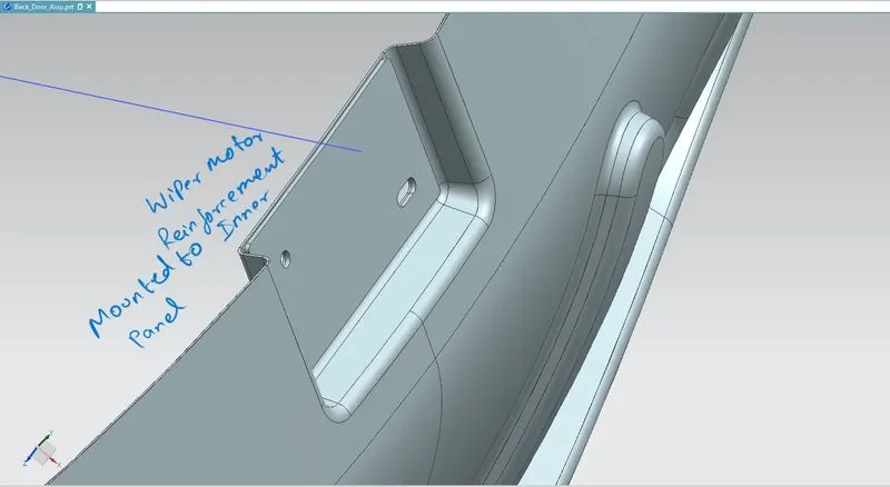
The inner panel is weakened due to giving the mounting regions and to add strength to the it reinforcement parts are created at the mounting surfaces.
Draft Analysis:
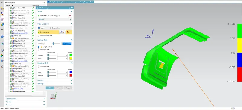
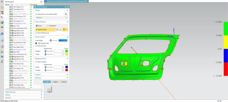
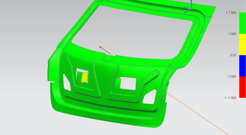
The draft angle for drawing process is checked with respect to the tooling direction created and the positive draft and negative draft areas are identified and the negative draft areas are removed.
Joining of Back Door:
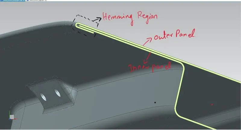
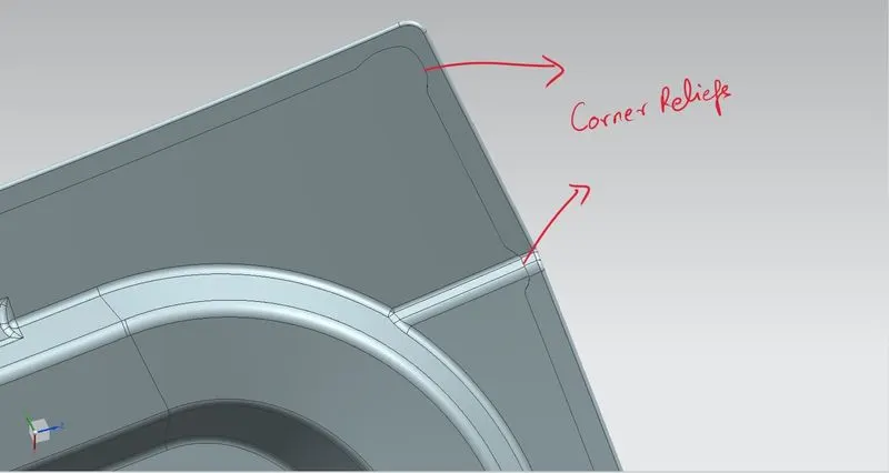
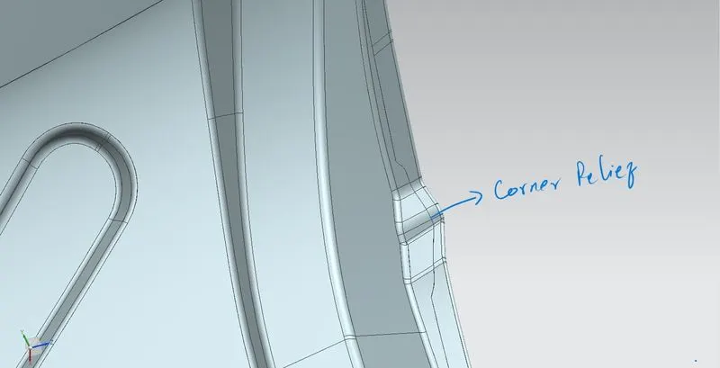
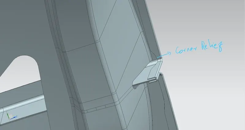
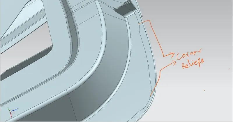
The inner and outer panels are need to be joined together but the main concern is that they cannot be welded because it would deteriorate the aesthetic look of the car and it lowers the premiumness of the car. So, they are hemmed together, hemming is the process technology used in the automotive industry to join inner and outer closure panels together (hoods, doors, tailgates, etc.). It is the process of bending/folding the flange of the outer panel over the inner one. The accuracy of the operation significantly affects the appearance of the car’s outer surfaces and is therefore a critical factor in the final quality of a finished vehicle. The hemming glue is introduced between the panels and outer panel is bent 180° towards the inner panel to hold it firmly. This in turns joins the panels as well as doesn’t affect the aesthetics and looks of the car. During the hemming process there will be wrinkled surfaces created at the corners and this would create more stress in the material so corner reliefs are provided to reduce the stress concentration and remove the wrinkled surfaces.
Manufacturing Processes for Sheet Metal/Backdoor:
The common types of sheet metal operations are shearing, blanking, punching, piercing, trimming, drawing, embossing, bending, and squeezing operations.
Shearing Operations
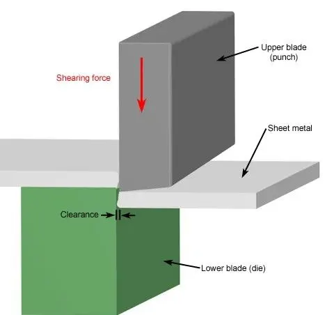
The Shearing operation is a cut in a straight line across a strip, sheet, or bar. It leaves a lean edge on the piece of metal that is sheared or cut. In this operation, a sheet metal workpiece is placed or kept between two dies from one end. And, the punch is hit at the other end of the sheet, producing a shearing effect. This type of sheet metal operation has three basic stages:
- Plastic deformation occurs when a metal is sandwiched between the upper and lower blades of shear when pressure is applied. It penetrates the metal for around 5 to 40% of its thickness.
- A fracture occurs at the spot where the most stress is concentrated.
- Shear – The metal is sheared once small fractures are discovered.
Blanking Operations
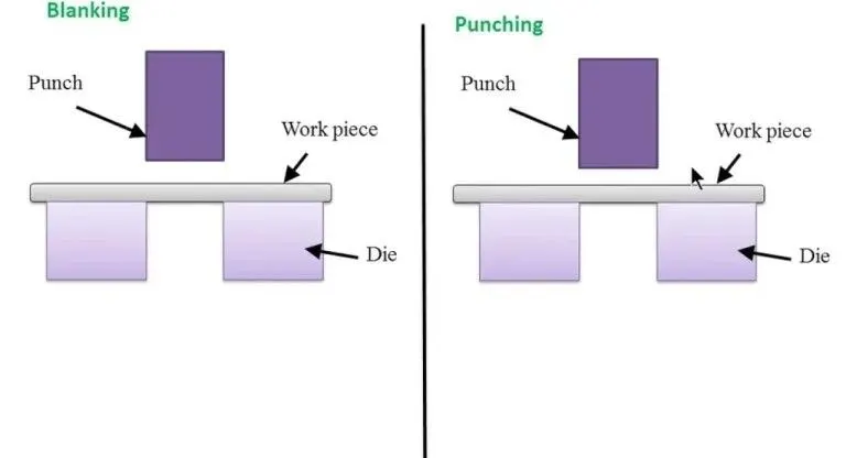
It is the process of cutting a complete piece of sheet metal. In which there is ample junk all around, as shown in fig. For this type of sheet metal operation, a punch and die are used.
Punching Operations
A punch and die technique is used to create circular holes in a sheet of metal. Although this is the polar opposite of blanking, the process is essentially identical. Blanking processes, for example, require the employment of a punch and die.
Piercing Operations
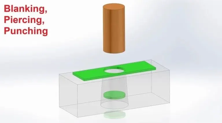
As indicated in the figure, piercing is the process of creating desired shape holes in a piece of sheet metal without taking any material from the sheet or removing a very little quantity of material. In this operation, both punch and die are used. Bullet-shaped punches are commonly employed in piercing operations.
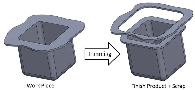
Trimming Operations
The shaving operation is another name for trimming. It is a finishing technique that involves removing burrs from cut edges in order to smooth them down and improve dimensional accuracy.
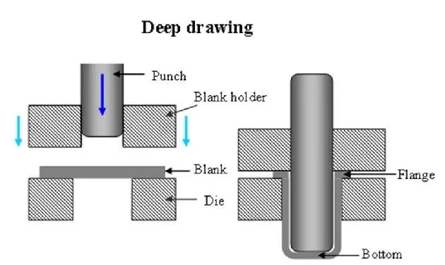
Drawing Operations
It is the process of fabricating thin-walled hollows or vessel-shaped pieces out of sheet metal. It can be classified into two groups:
Deep drawing – the object to be drawn has a depth that is greater than its breadth.
Shallow drawing – the item to be drawn has a length that is less than its width. Pans, tubes, and cams are instances of drawing.
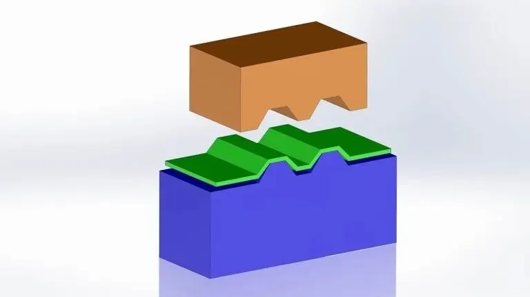
Embossing Operations
It’s a metalworking technique for creating raised surfaces or letters in sheet metal. During this operation, the thickness of the metal does not change.
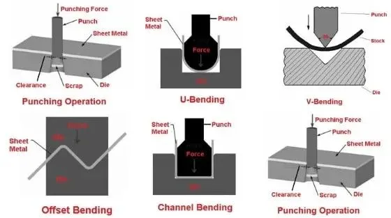
Bending Operations
When forces are applied to certain regions, this happens. With the inner surface under compression and the outer surface in tension, the metal flow is uniform along the bend axis. The following are the various types of sheet metal bending operations:
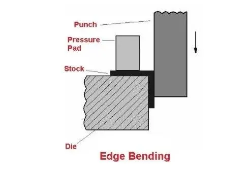
Edge bending
As indicated in the diagram, it is a type of bending operation in which a piece of sheet metal is fixed or held between two dies from one end. The other end is thus compelled to strike the free or unfixed punch. To complete the shaping process, the sheet metal piece’s free or unfixed edge is bent.
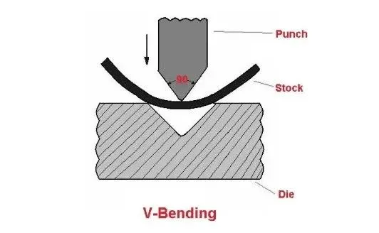
V-bending
When a piece of sheet metal is squeezed between the die and the punch in this type of bending operation, it is shaped into a V-shape in the die.
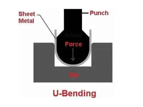
U-bending
The sheet metal component is shaped into a U-shape in this type of bending operation, in which the punch is forced into the die by a force.
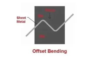
Offset bending
It is a type of bending operation in which a piece of sheet metal is punched and die-formed into an offset shape.
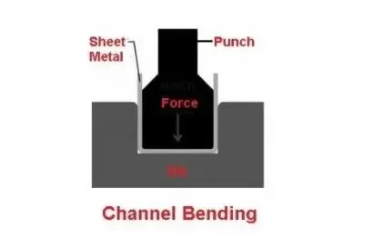
Channel bending
When a force is applied to the punch to advance it into the die, the sheet metal piece in between the punch and die takes on the shape of the die and punch, i.e. a channel shape.
Squeezing Operations
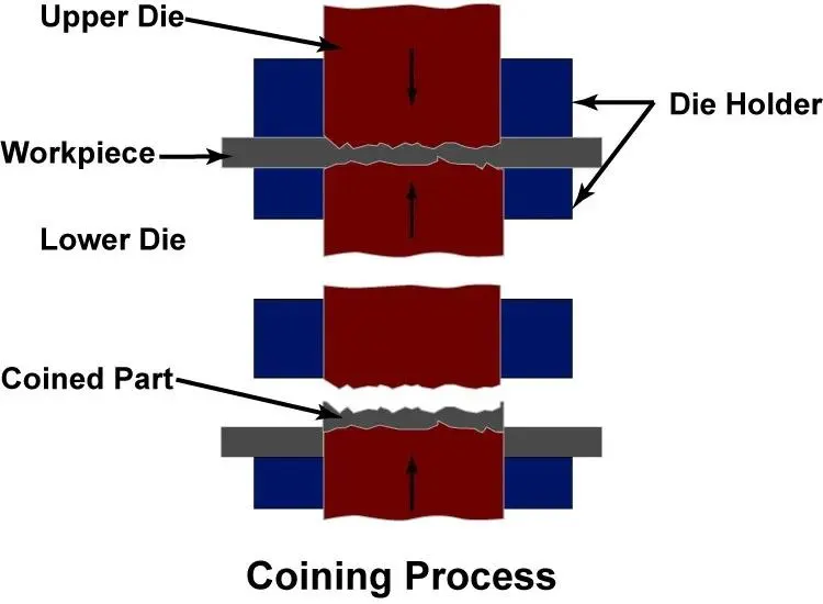
It is a simple and common method of producing ductile metals. It can perform a variety of tasks, including sizing, coining, and riveting.
Sizing – the sizing technique decreases the thickness of the metal by squeezing it. Only the surface where the die and the workpiece come into contact is sized in an open die.
Coining – It’s the process of pressing metal into a die and allowing it to flow into the die space. Medals, coins, and jewelry, for example.
Hemming Operations:
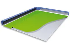
Hemming is a forming operation in which the edges of the sheet are folded or folded over another part in order to achieve a tight fit. Normally hemming operations are used to connect parts together, to improve the appearance of a part and to reinforce part edges.
In car part production, hemming is used in assembly as a secondary operation after deep drawing, trimming and flanging operations to join two sheet metal parts (outer and inner) together. Typical parts for this type of assembly are hoods, doors, trunk lids and fenders.
The accuracy of the hemming operation is very important since it affects the appearance of the surface and surface quality. Material deformations, which occur during the hemming process, can lead to dimensional variations and other defects in parts. Typical hemming defects are splits or wrinkles in the flange, material overlaps in the corner areas or material roll-in. This is why it is important to use simulation tools in order to, on the one hand, better understand the hemming process and, on the other hand, significantly reduce the number of “trial and error” loops during tryout und production.
There are various types of hemming operations:
- Conventional die hemming
- Roll hemming
 |
 |
|
In conventional die hemming, the flange is folded over the entire length with a hemming tool. |
In roll hemming, the hemming roller is guided by an industrial robot to form the flange. |
Conventional die hemming
Conventional die hemming is suitable for mass production. In die hemming, the flange is folded over the entire length with a hemming tool. Normally the actual hemming is a result of a forming operation in which the flange is formed with a hemming tool after the drawing and trimming operations have been completed. The formed flange is then hemmed in several process steps. These steps include, for example, the pre-hemming and final hemming depending on the respective opening angle of the flange. Production plants for conventional die hemming are very expensive, but the cycle times are very low.
Roll hemming
Roll hemming is carried out incrementally with a hemming roller. An industrial robot guides the hemming roller and forms the flange. Roll hemming operation can also be divided into several pre-hemming and final hemming process steps. Roll hemming is very flexible to use and tool costs are significantly lower as compared to those of conventional die hemming. However, the cycle times are much higher since the hemming is realized using a hemming roller which follows a defined path.
Errors Faced During Design:
- Error while trimming the inner panel for hemming clearance due to complexity of the surface
- Error during the creation of reinforcement parts due to the selection of wrong reference surface
Measures Taken to Rectify:
- Created the trim boundaries that are free from irregularities and used them to trim the panel
- Selected the correct reference geometry and updated the entire model of each reinforcement
Conclusion:
Hence the design of back door is completed by repairing the given Class – A surface, with all the necessary panels, mountings, reinforcements and with all the compliance regulations and all clearances and dimensions.