Design of backdoor
Back door/tail gate/trunk door is referred to the closure component of a vehicle which opens and closes on the rear side of it. It is connected to the side body by hinges depending on the type of its design. The function or need of a back door is that it saves the occupants and luggage from getting affected by the harsh environemental conditions like rain, snow, sun light etc.
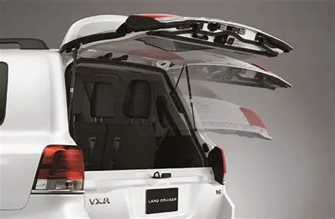
It is not only a protective component but also the last component of the car that anyone sees when a car passes by. The tail gate is similar to a hood but has some more features in it. The door is designed in such a way that it gives enough room for the boot space. The design should also follow the aerodynamic line that is followed right from the front bumper component. This is really important in terms of aerodynamics as when the air leaves the car surface at the rear end, develops a pressure difference(high and low pressure zone). This is when the flow of the air gets seperated.
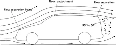
The air flows high pressure to low pressure area which if is greater would increase the drag and reduce the speed of the car. This is followed in cars developed keeping performance into consideration.
Modern car not only have the back door but also some portion of the tail lamp and as usual the number plate.
There are basically 2 types of tail gates.
1)Roof Mounted gate - In this type of car, the tail has hinges on the top flanges which helps in mounting the gate on the roof region. The door opens in upward direction. Generally, this door is kept a bit light but of course heavier than all the other closure components.
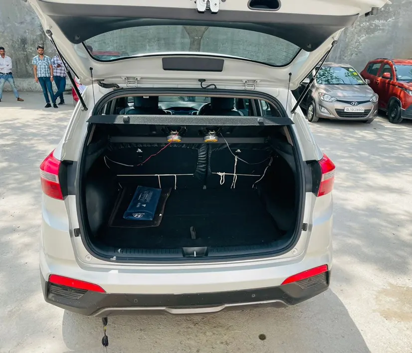
2) Side mounted gate - In this type of car, the door has hinges on the side flange. In this manner, the door gets mounted to the side body of the car. In this type of design, the gate opens and closes sideways.
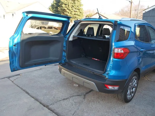
In side mounted gate cars, the designers are allowed to go for heavier back door as it doesn't has to be lifted and necessity of a high strength gast stay is not required. Angle of the door opening is kept small to avoid greater opening of the door which may lead to road accidents due to on coming vehicles on a busy road. In this type, there is another option of having dual door design as seen in ambulances and fire vehicle. This is given in cars where quick and frequent opening of the door is observed.
3) Combination gate - In this type of car, there is a combination of liftgate and tailgate as a set of doors. 1)opens upside 2)open downside. This is provided in cars which deals which deals with logistics. The lower gate is used as a support to slide the goods for unloading and loading purpose.
Tail gate is made of inner and outer panel just like the hood. It is designed keeping the safety in mind and so necessary embossing is given in order to absorb and divert the forces from making huge impact on the central region of the door. This is done in order to reduce the damage in any rear collision.
The tail door also contains the sealing flange on which the rubber would sit and help the rear portion of the car to get air tight and form a perfect fit.
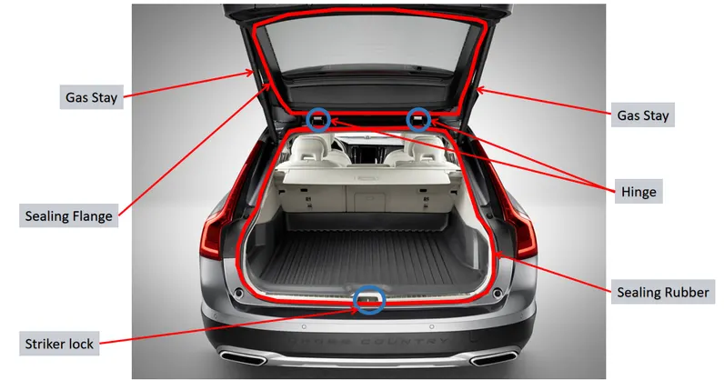
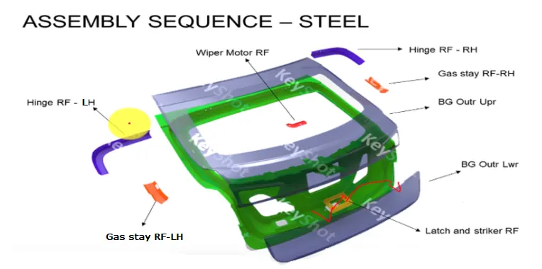
The door also has different mounting flanges for components like striker,hinge and gas stay. The gate should be as thin as possible in order to get more boot space for passenger and luggage capacity. It basically has a window but small compared to the large front screen. The glass has to be kept clean so a wiper system is provided to achieve the goal so additional mounting flange is given for the wiper motor to be installed on. The window is given for the driver to judge the car following. The thickness should be small for space but it should be big enough for all these components that are fitting on the tail gate. Where ever the mountings are given, that region has less strength. So, to improve the strength of these regions, neccesary reinforcements are given.
Tail gate is produced with aluminium which makes the part lighter with varied local thickness. This is done to make the part as thin as possible and also the smaller angle flanges can be created. But this comes with increase in cost of the part due to heavy machinery that is used for the production.
1) Hinges are used to assemble the door to the body of the car with the help of fastners.
2) Stiker is the lock which completely locks the door to the car body in closed position.
3) Gas stays are mounted on either side of the tail gate which keeps the door in open condition without any human effort. Once the door is opened, the cylinder piston design of the gas stay avoids the door from falling down by chance. In order to close the door, a certain effort is applied on the door to close the door.
*) The table shown below gives a comparative information about Steel and Aluminium.
| Aluminium | Steel | |
| Parts | Parts are casted | Parts are stamped |
| Reinforcements | Reinforcements can be neglected | Reinforcements are necessary |
| Thickness | Thickness can be varied | Thickness should be uniform |
| Weight | Lighter in weight | heavier in weight |
| Cost | Costly as compared to Steel | Cheap as compared to Aluminium |
| No. Of components | Less No. of components | More No. of components |
PRODUCTION
Tail gate is produced by stamp pressing. In this process, a core and a die is required.
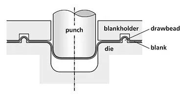
Die is the exact shape of the part that has to be produced. Core is of the shape of the hole of pattern that is required. The core is fixed firmly and the sheet metal is loaded and fitted just over the die. The core slowely presses it to a re-determined value. When the core is withdrawn back, the sheet is obtained with the desired pattern. Reinforcements can be either stamped or casted depending on the material used to produce one.
Earlier, whole outer panel was produced as a single component but now due to the developement in the design of the cars, tail gate is produced in smaller parts and later spot welded to create a single component.
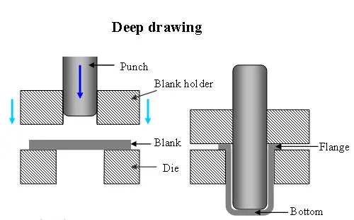
*) Deep drawing - It is also known as hydroforming in which metal sheet blanks are radially drawn into a forming die by mechanical action of a punch. It is thus a shape transformation method with material retention.
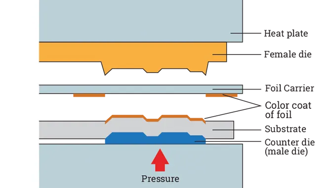
*) Embossing- It is a process of producing raised or shrunken design or reliefs in sheet metal by means of matched male and female roller die with no change in sheet thickness also with desired pattern. Metal sheet is drawn in a male and female roller die.
*) Deep drawing- This is method used for producing back doors especially. The process is carried out in two steps
i) First step drawing- Blank sheet is placed on a die and contact with punch. The punch is moved towards the die vertically. The outer rim of the sheet is completely under radial drawing between the die and sheet blank. The portion in contact with the punch gets bend into the desired shape and the sheet also gets little elongated.
ii) Redrawing- The components drawn from the first stage is again redrawn into more depth to give it the exact desired depth
*) Hemming- It is end process after the panels are created in which the sharp edges are folded over another part in order to achieve the desired perfect fit. This is not only done to fit the parts but also to improve the aesthetics of the overall produced part. It also gives strength to the edge region of the part.
There are various types of hemming operations:
1) Conventional die hemming- In this process, the entire length of a flange is hemmed over the part edge with the help of a hemming tool.
2) Rolling hemming- In this process, a inductrial robot is used to move the hemming roller over the flange to complete the process.
*) Open hemming- It has a full round feature and a return flange with bend angle of 180 degrees.
*) Tear drop hemming- Here, the same process is followed but the bend angle is greater than 180 degrees.
*) Closed hemming- Hem parts with no inside radius are categorized into closed hemming. Closed hemming is done only only parts where they aren't to be painted or the material used is SST or aluminium.
Design in NX-12 software
*) The design parameter considered are:-
i)Thickness of the panels
outer panel-0.75mm
inner panel-0.75mm
mastic glue gap-0.2mm
ii)Edge distance =6-8mm
iii)Corner reliefs where ever the sheep has bend curves
iv)Reinforcement =1.5mm
1) The outer panel was opened and it was repaired and sewed to form two different components as upper and lower outer panel.
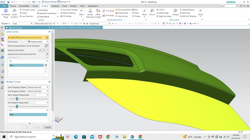
Upper and lower outer panel are spot welded so the flange was kept to 8mm.
2) The panels were loaded as assembly and the inner panel was created begining with sealing flange. Offset tool was used for working and later law extension was used to create the flange.
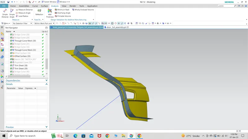
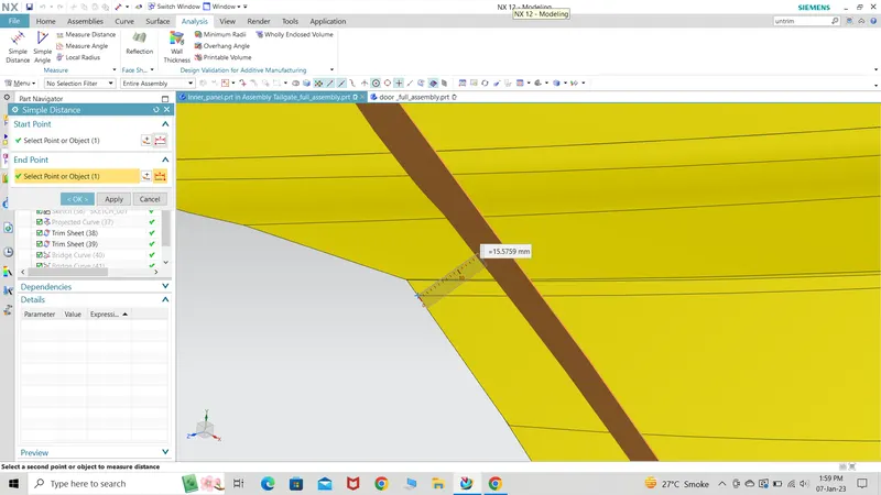
The sealing flange was kept >12mm for improved strength of the overall component.
3) Trim and extend, bridge curve and law extensions tools were used to create the full inner panel
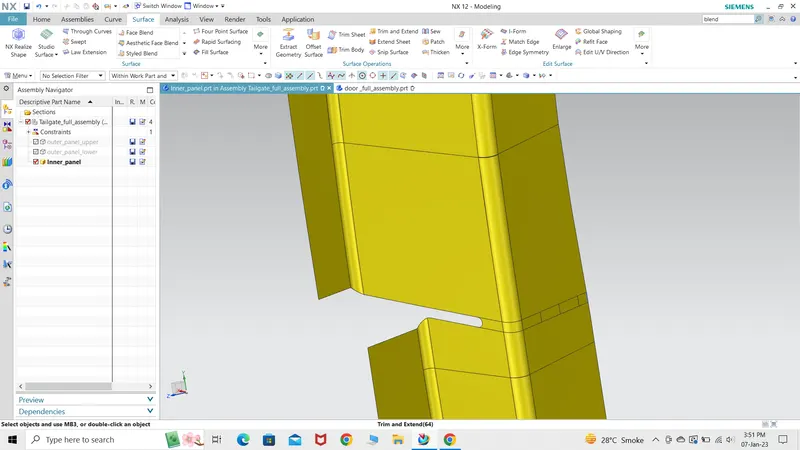
The portion where upper and lower outer panel gets welded has to be kept in mind while designing the inner panel. The panel which would fail in draft analysis was removed to give the panel a simple design.
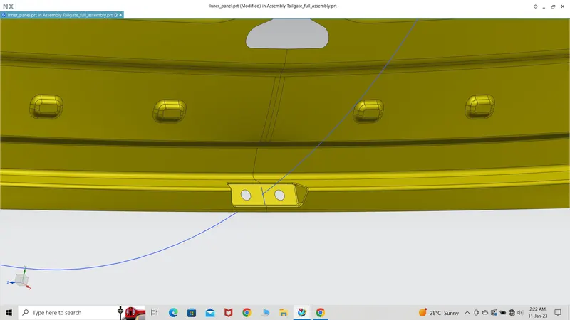
4) Mountings for hinges and striker and gas stay was created with the help of sketch, law extension. The vector that was used to create the law extension was chosen as the tooling vector.
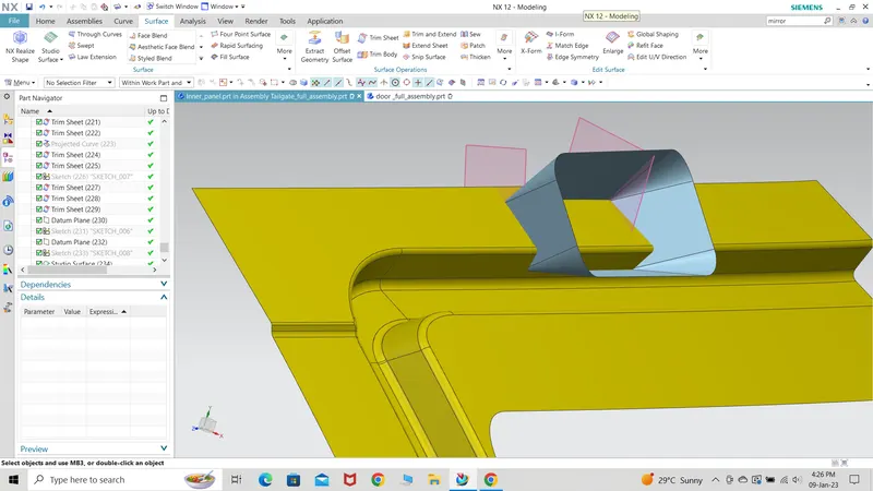
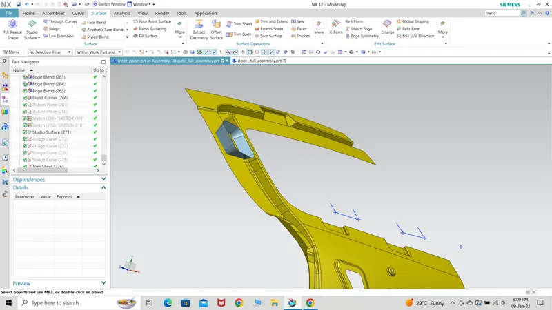
This portion was carefully created as it may lead to failure in execution of thicken command.
For stricker creation, it was necessary to mirror the component and later, create the trajectary circle taking the hinge as the centre of the same circle and later create the mounting flange perpendicular to this circle as shown below.
5) Y embossing was giving as by several tests it was observed that this particular region goes through high stress and this is the reason, such a design was adapted. The inner panel also comprises of rear glass region embossing which is on the other side of the panel so as to avoid interuption at the time of rear glass fitting.
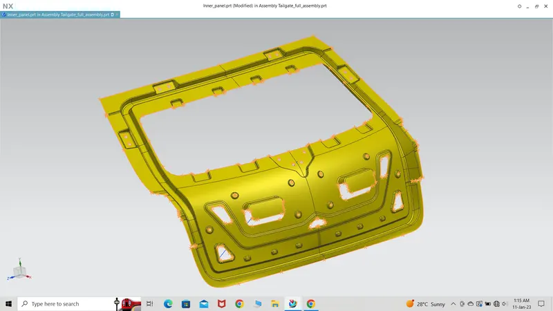
Center mastic flange were developed to give the central portion of the part to get a proper joining with the outer panel and improve strength of this particular portion.
Several cut-outs are also given in order to get easy access to the tail light assembly for tail lamp fitting. Some cut-outs are also given for the holding the panel at the time of production without giving any scratch to the part for lifting and movinig the part.
6) The reinforcements were created as a seperate assembly part by taking the inner panel as reference.
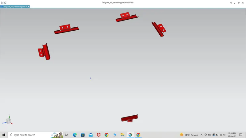
The right side of the reinforcements were simply created by mirror assembly option and later fixing them to that location.
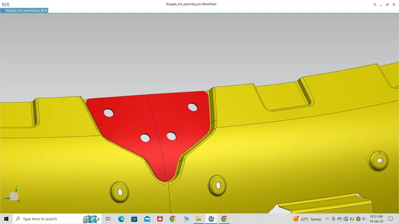
Wiper motor embossing also needed to be strengthened so this portion was also given a reinforcement.
7) The outer panel was mirrored and later hemming was done taking 8mm as inner flange width. Inner panel was reduced by some mm in order to get a perfect fit.
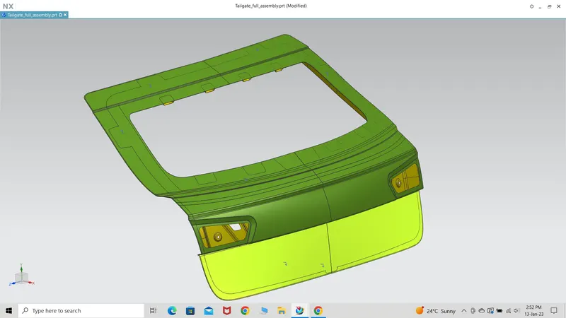
In creation of all the parts, the corners were properly given corner reliefs so that the part doesn't face any wear and tear at sharp corners due to continuous rubbing with the counter parts. The distance between the inner and outer panel was maintained to 0.75mm.
8) Corner reliefs were given where ever necessary. All the panels were created and thickened.
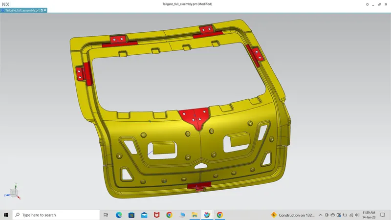
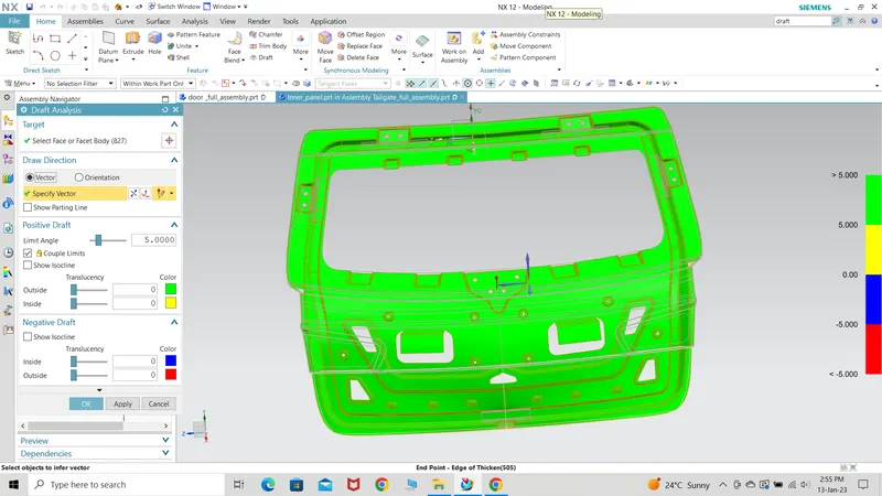
*) Draft analysis was performed and the result is as follows:-