Design of backdoor
AUTOMOTIVE DESIGN OF BACK DOOR USING SIEMENS NX CAD
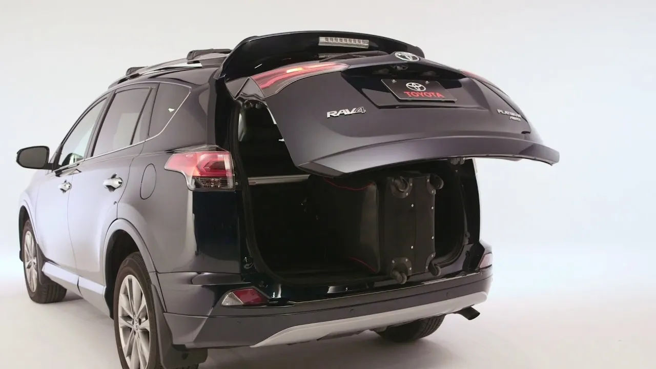
AIM
Use the provided styling surface to come up with a back door design, use appropriate design methodologies, and provide the necessary reinforcements and embosses
Software Used
Siemens NX CAD
INTRODUCTION
Introduction Back door of the car is also known as Tailgate. This is a critical part for back impacts occur on the accidents, which should be ensure that crash… To create the back door inner panel, outer styling panel with Hemming and reinforcement using NX software with the help of the styling surface provided.
A Tailgate of a car, the car for being sequentially mounted by a tailgate inner panel and a Back Door out panel to a tailgate thereof, which the tailgate outer panel is hinged to a tailgate which is vertically openable and closeable, wherein the tailgate comprises a glass plate, a first mounting bracket (or a first mounting pivot) coupled to the tailgate outer panel and a second mounting bracket (or a second mounting pivot) coupled to the glass plate, where the first mounting bracket (or the first mounting pivot) and the second mounting bracket (or the second mounting pivot) are hinged together, such that the tailgate is simple in structure thereof, parts involved are reduced and assembly is easy with manufacturing cost decreased and a beautiful exterior look.
The material used for door manufacturing depends on the budget and performance of the vehicle. Mostly Aluminium and Steel will be used whereas low-budget vehicles use Steel which makes the manufacturing process easy and cost-efficient since it follows the Stamping of Moulds.
DESIGN INTENT
The intent of the project is to design a Body in White Back Door of the vehicle considering the engineering standards and manufacturing requirements which satisfies the Deep Drawing Process.
DESIGN CONSIDERATION OF A BACKDOOR
- Functional Requirement of Hinge and gas stay
- Rear visibility criteria
- Luggage volume
- Crash Analysis
- Bend Test, Dent Test, Torsion Test & Endurance Test
- Rear Crash Regulation
- Gap and flushness Requirements
METHORD OF JOINING
MASTIC JOINT
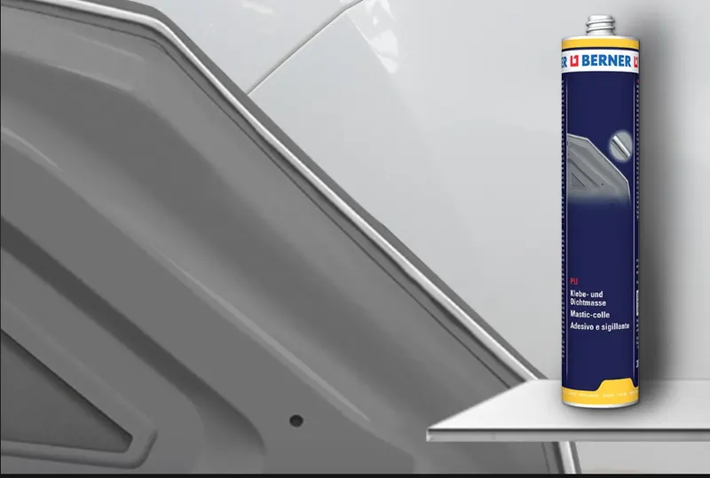
Its also called as the adhesive sealent. It is of the rubber type material so that it can absorb the viberation, by this we able to both join the two surface and also to reduce the noise due to viberation.
Spot Welding
The PN-EN 74-1:2006 standerd defines the parameters of the spot welds in relation to the thickness of the sheets. For class A welds is making by the hydrolic or pneumatic clamping of the anode or cathord
Major Parts and Reinforcements:
The backdoor consists of the following basic components:
- Backdoor Outer Panel (Upper)
- Backdoor Outer Panel (Lower)
- Backdoor Inner Panel
- Hinge Reinforcements (LH & RH)
- Gas-Stay Reinforcements (LH & RH)
- Latch and Striker Reinforcement
- Wiper motor Reinforcement
TOOLING DIRECTION
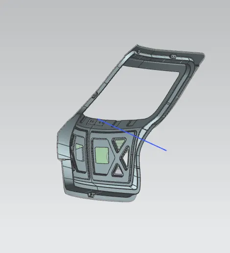
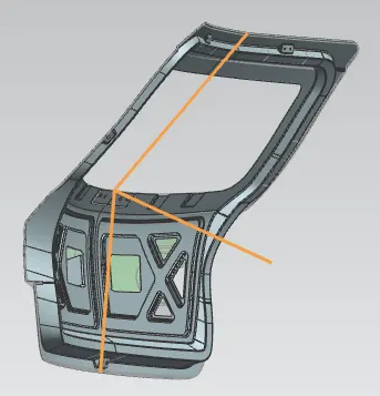
Before starting to design the inner panel of the back door the tooling direction for Deep Drawing purpose should be created.
Then the styling surface needs to be checked and analysed since it might have irregularities, hence it must be fixed first.
Then the back door was designed using the top-down approach.
DESIGN OF BACKDOOR OUTER PANEL
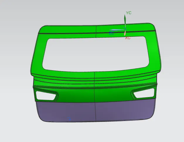
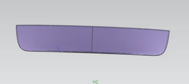
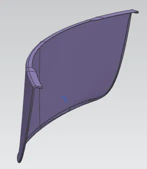
The Outer Panel is the styling surface of the back door, also deals with the aesthetics of the car. Other components of the backdoor are designed with reference to the outer panel. It acts as the outer cover.
In this design outer panel is of two parts
- Outer Upper Panel
- Outer Lower Panel
Outer Upper Panel is extracted from the styling surface the back door given. The complicated areas are edited and create smooth surface within the design criteria. All are altered using the surface tool in the NX CAD software. Hemming is provided with corner relief. Thickness is of 0.75mm is provided.
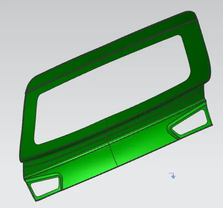
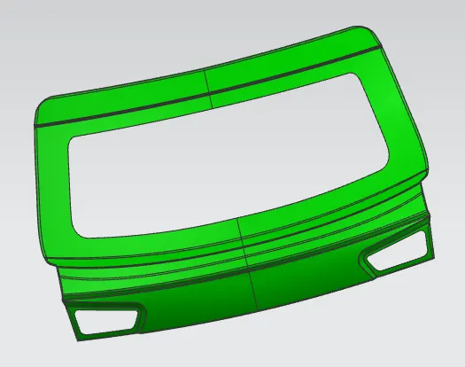
The same process is done for the Outer lower panel.
Backdoor Inner Panel
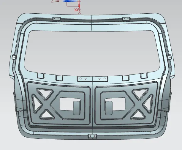
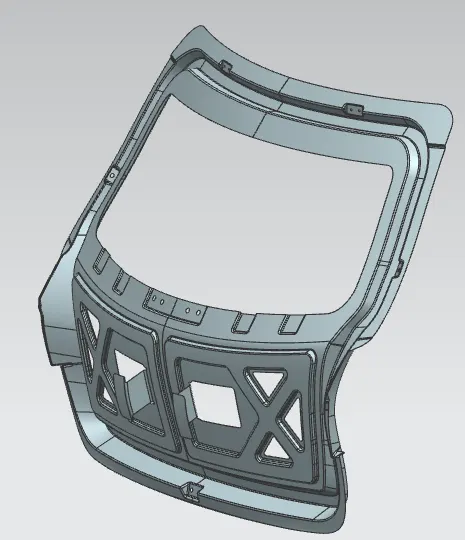
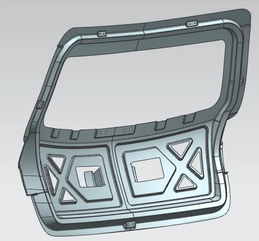
After creating the outer panel next, we need to create the outer panel. For the design of the inner panel, we will first develop an effective sealing flange by checking all the boundaries and by following the shape of the inner panel design. By creating multiple flanges and by using surface modelling techniques the concept design of the inner panel was created.
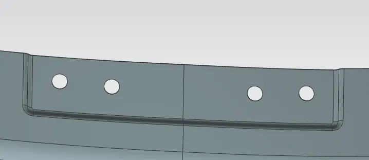
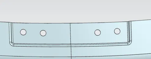
Then create the embosses for the
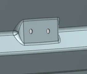
Hinge embosses
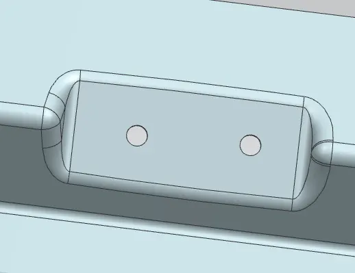
Latch and Striker embosses
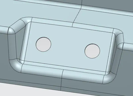
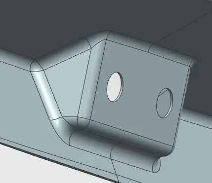
Striker Position:
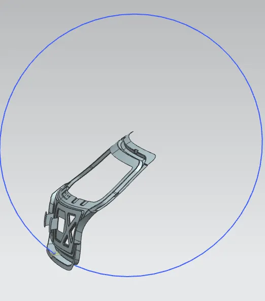
The position of the hinge should be perpendicular to the latch when the latch and striker meets. The circle is drawn from the centre of the hinge axis to find the path of the striker and positioned perpendicular to the path.
The Latch and Striker emboss were designed by creating a trajectory that follows the opening and closing of the back door with respect to the hinge axis.
Gas stay embosses
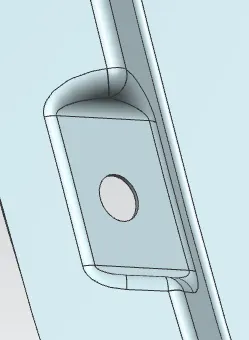
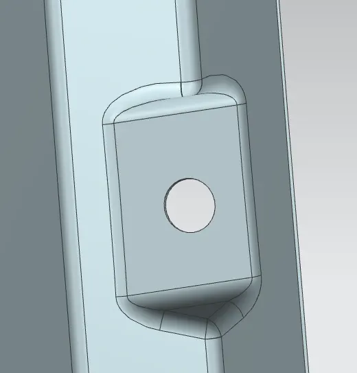
Viper motor mounting embosses
Reinforcement
It is an extra part given to the module for improving the strength/compensate the loss locally. These parts could be made from outer body scraps. Thickness could usually vary from 1~1.5mm.
After the concept of the inner panel is developed, then the child components like a
Hinge
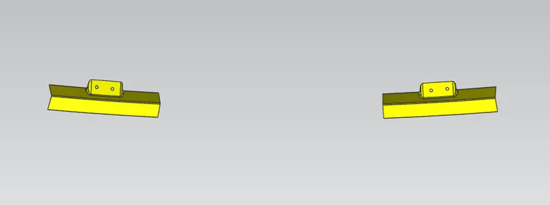
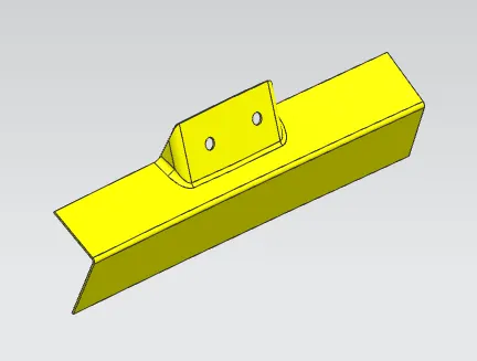
Latch and Striker
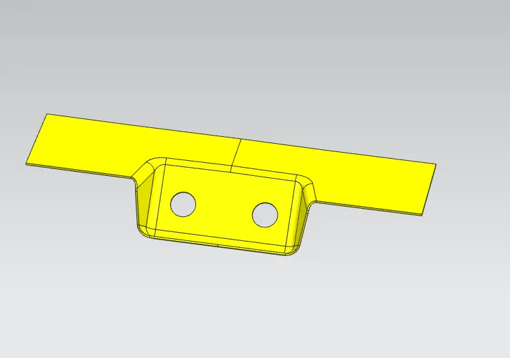
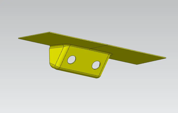
Gas-Stay Locations
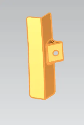
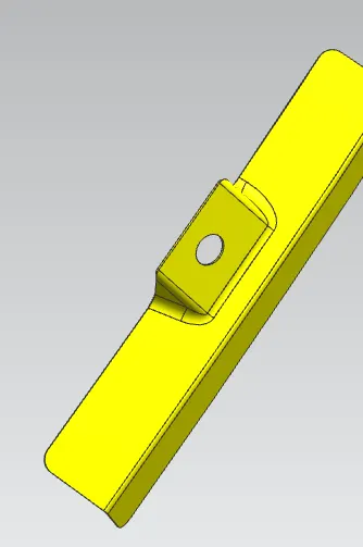
Viper Motor Reinforcement
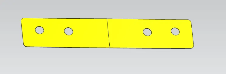
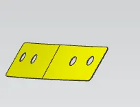
The embosses are created, so that if the vehicle undergoes the crash, then the force dissipates over it which reduces the damage transferred to the trunk space.
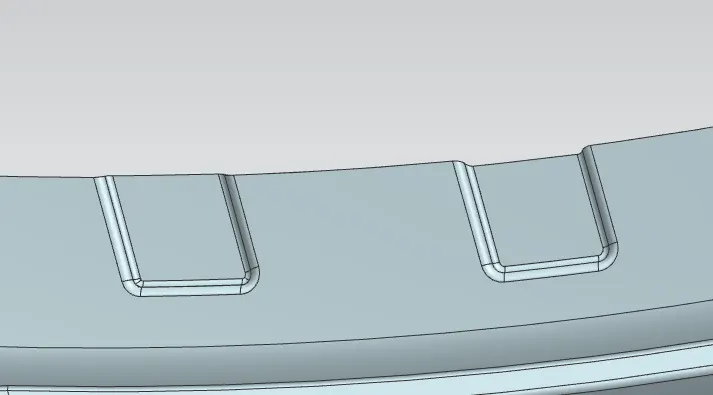
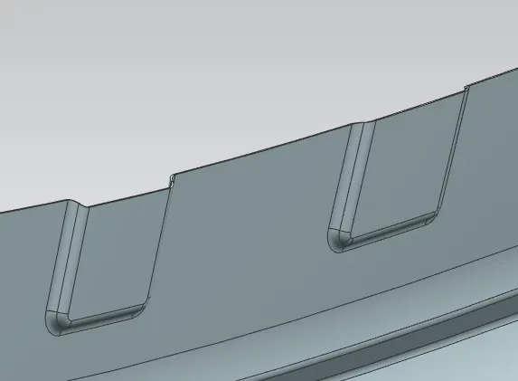
HEMMING
Hemming and seaming are two similar metalworking processes in which a sheet metal edge is rolled over onto itself. Hemming is the process in which the edge is rolled flush to itself.
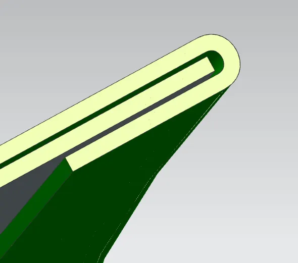
After designing the outer panel, the Hemming was created by offsetting the surface with the help of face blend and swept surface.
The two separate outer panels will be joined using Blanking.
CORNER RELIEF
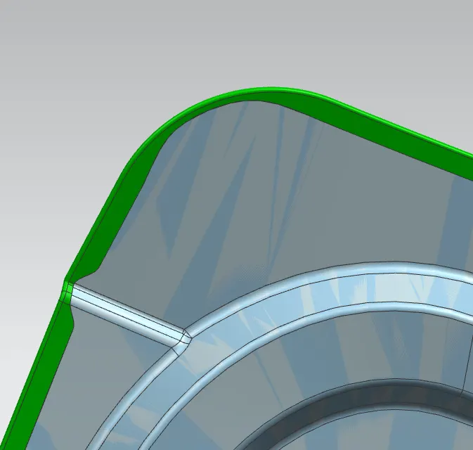
During the hemming process, when giving the Corner Relief helps to control sheet metal material behaviour and to prevent unwanted deformation during unbend operations and also helps to reduce the number of passes in hemming.
DRAFT ANALYSIS
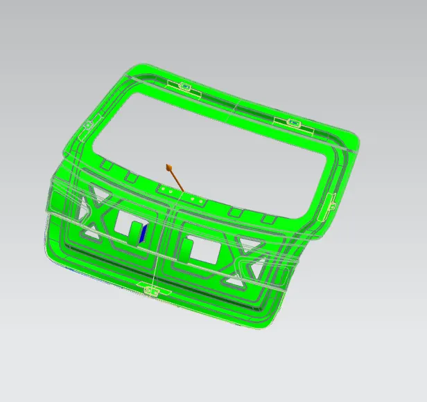
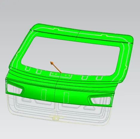
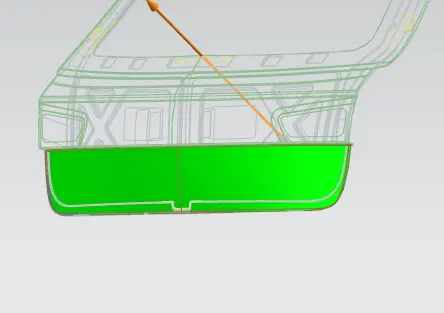
The draft analysis will be performed for the tooling direction created at first and checked that the model is suitable for manufacturing.
Then to get a complete green portion the necessary changes to the draft angle of the embosses were carried out by optimizing the model.
The Draft Analysis command enables us to detect that the part drafted will be easily removed or not.
This type of analysis is performed based on colour ranges identifying zones on the analysed element where the deviation from the draft direction at any point, corresponds to specified values.