Design of backdoor
Use the provided styling surface to come up with a back door design, use appropriate design methodologies, and provide the necessary reinforcements and embosses
Introduction to Backdoor
The backdoor of a vehicle is the rear most opening in a car that provides entry to the luugage area of the vehicle or as more commonly known as the boot. The backdoor is also the body panel that has the mounting for the tail lamps, number plates and the rear windshield in some cases. The backdoor is also more commonly termed as Tailgate and Bootlid.
The design of the backdoor must be carefully considered as it houses many important components of the vehicle at it's rear end and aside from housing the physical components, it also plays an important factor when it comes to rear visibility and rear luggage space. Like the hood of a vehicle, the backdoors are also designed in a way such that, in the case of a rear end collision, the backdoor plays a role in diverting the impact energy away from the passenger cabin by providing various load paths to the rear pillars and other components in the vehicle structure.
The backdoor is usually constructed of steel or aluminium depending on how expensive the vehicle and the budget for its development.
Similar to the construction of the side doors and the hood in a vehicle, the backdoor also consists of a Outer and Inner panel.
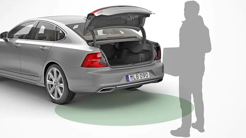
Components of the Backdoor designed:
1) Outer Panel (Upper)
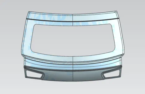
The outer panel was done in 2 parts, the upper and the lower part. We first see the design of the upper panel which was provided with a thickness of 0.75 mm.
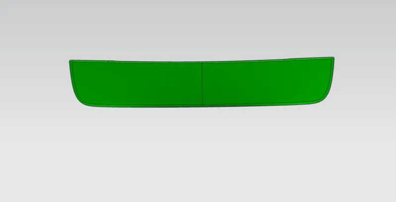
2) Outer Panel (Lower)
This is the second component in the outer panel. The image below shows the lower half of the outer panel, which was once again provided a thickness of 0.75 mm.
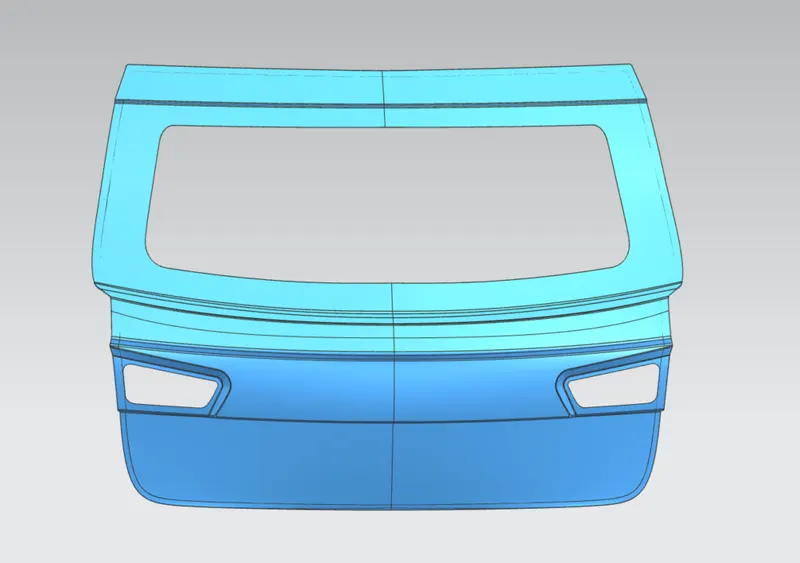
The image below shows the entire backdoor outer panel, this includes the upper and lower outer panels and signifies how they are joined together and seen in the real world.
3) Inner Panel
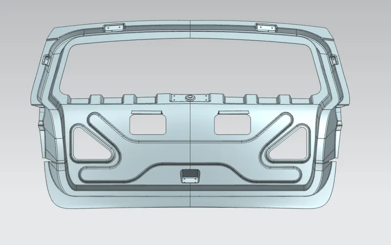
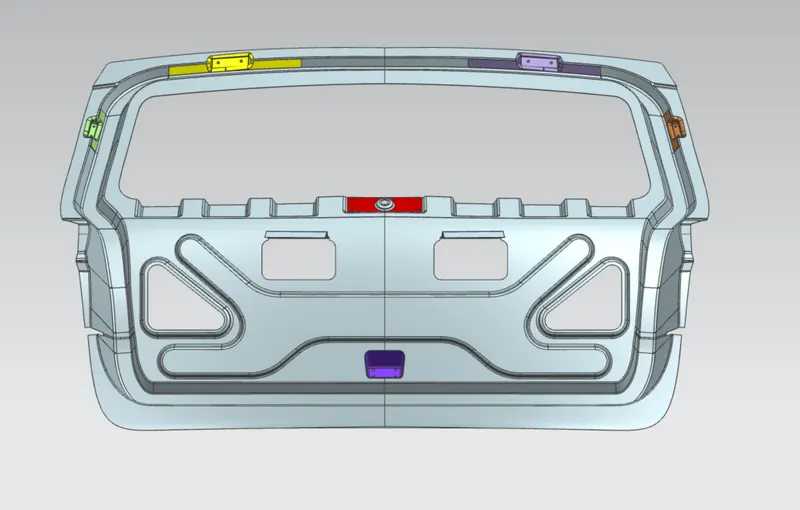
The inner panel of the backdoor is where the majority of the design in this project was undertaken. You will notice in the image below that inner panel of the backdoor house the hinge mounts, gas stay mounts, wiper mounts, the mount for the latch for the backdoor and contains the cutouts to assemble components like the tail lights and such and embosses that help with strenghtening the door in the case of collision to ensure that the passengers are safe inside the cabin and most importantly, the sealing flange, the area of the backdoor that provided a dust free and water tight seal to ensure the components inside do not deteriorate when exposed to such natural elements.
The inner panel also contains the flange that is cutout from the panel itself through the method of lancing and the mastic sealent is applied on this surface the attached to the outer panel. A gap of 5 mm was kept to ensure the proper application of the mastic sealent.
Reinforcements:
The backdoor is provided with mulitple reinforcements as it contains multiple mounting points for parts that apply an additional stress in that area locally. These reinforcements are purely there to compensate for the weakening of the panel in that particular area. The reinforcements are provided an extra 1.5 mm thickness.
There were 6 reinforcements created in this model and they are listed as below:
1) Gas Stay Reinforcements (LH & RH)
This is the area where one end of the gas stay is fixed to the back door while the other end is fixed to the body side.
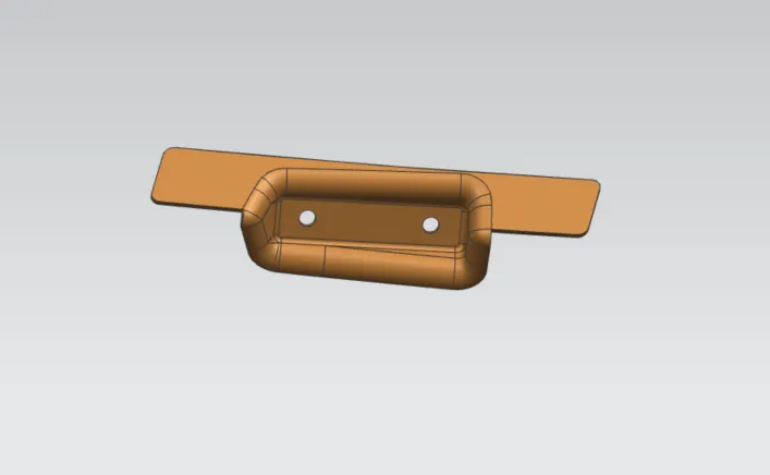
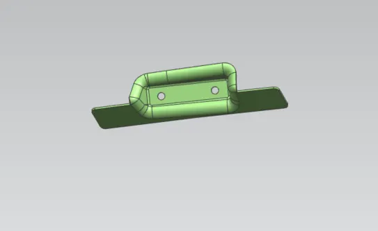
2) Hinge Reinforcement (LH & RH)
The hinge reinforcement,like the gas stay reinforcement , is attached to both the back door and the body side panel. This is where the hinge for the backdoor's opening and closing is placed.
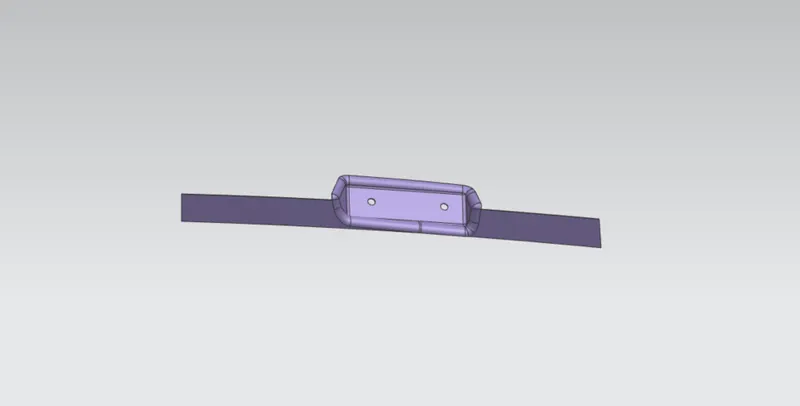
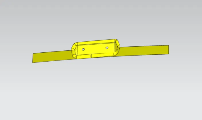
3) Wiper Motor Reinforcement
This is where the wiper motor for the rear windshield is fixed and this additional weight requires the introduction of a reinforcement locally.
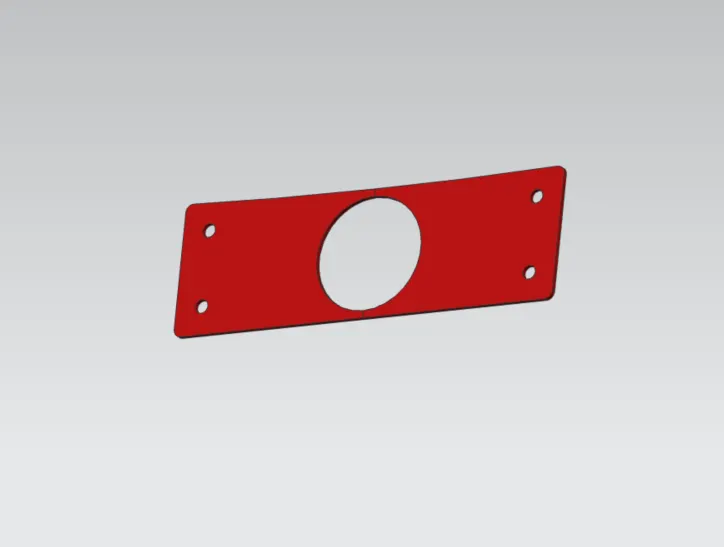
4) Latch & Striker Reinforcement
The area where the mount for the latch is situated is susceptible to damage as this is the area where, when the backdoor is closed or slammed, the striker comes in contact with the latch and locks the door.
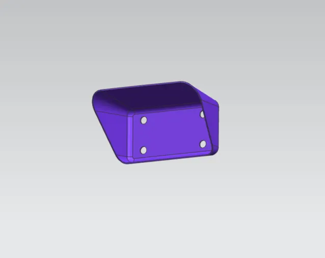
Striker Positioning:
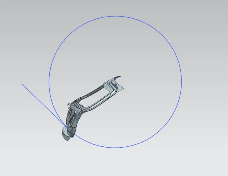
As seen in the image, the hinge axis was first considered and the a circle was drawn taking that hinge axis as its center. This circle shows the path the striker will follow. A line perpendicular to this was created and the latch mount was created from that perpendicular line.
Hemming:
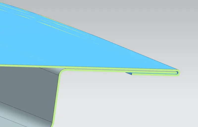
Hemming is the method of choice for the joining of the outer and the inner panel in this case. Hemming is used as the outer panel, which is considered a Class-A surface, cannot have any marks or blemishes that would cause it to look aesthetically any less than perfect. Hence we cannot use the traditional methods of welding as this would cause undesired marks on the outer panle surface and this is why we use the process of Hemming to join the two panels.
Corner Relief:
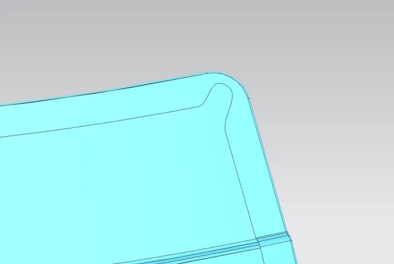
Corner reliefs were provided in the design, so as to prevent the overlapping of the sheet metal at the edges during the hemming process and also to provide a relief to the stress concentration in that area.
Draft Analysis:
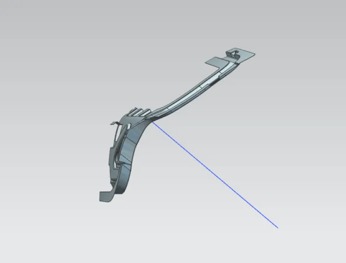
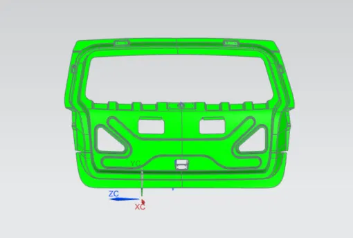
A draft analysis was conducted finally to see if the final design was drawable. This was done with the construction of the tooling direction. This tooling direction was used as a reference vecfor the construction of this model. The images below shows the draft analysis results and also the tooling direction that was used.
Conclusion:
The backdoor was designed from the provided skin data adhering to all the required standards.