Design of backdoor
Aim:
To design the Back door of an automobile considering the necessary design standards.
Objective:
The main objective of this project is to design the Back door of a car by using the styling data using the appropriate design methodologies. To develop essential flanges, reinforcements, embosses and mounting points on the inner panel of the back door. To perform Draft analysis and section inertia analysis on the door design.
Introduction:
Back Door:
The Back door or Rear door or Tailgate is one of the important closure components positioned at the rear end of the car. It simple terms, it can be opened or closed hence, it is put under closure components category of the BIW (Body in White) layout.
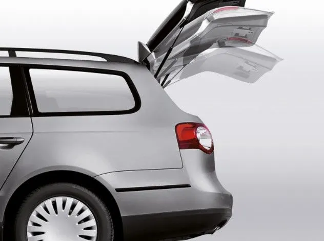
Fig:1-Back door
The main use of back door is to cover the back of the car. It is a swinging component which covers the storage compartment for bags and luggage.
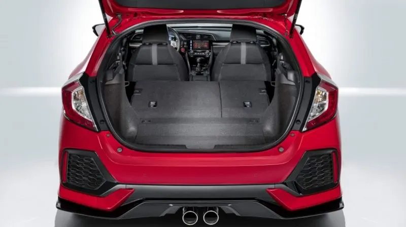
Fig:2-Storage Compartment
Design methodology:
The Backdoor design is optimized such that its thickness is minimal and more space is present for the storage compartment. But it is ensured that its strength is maintained, the backd door should be able to withstand the impact during a rear collision. The outer panel of the back door is mainly for aesthetic improvements. The inner panel helps in increasing the strength of the back door. It has mounting points for hinges, latch, gas stay and embosses to improve its strength.
Material used for Back door sheet:
Steel and Aluminium are the most frequently used materials to produce sheet metal components. This is a comparison between Steel and Aluminium in terms of Sheet metal design.
| Steel | Aluminium |
|
|
Since the Aluminium parts can be casted and they help in weight reduction, in recent times Aluminium is used to produce the sheet metal parts. But the cost of production for Aluminium is more hence Steel is preferred for manufacture of Sheet metal components.
Manufacturing of Backdoor:
1. Carbon Steel is used for the manufacture of sheet of door.
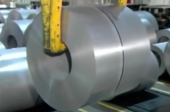
Fig:3-Steel roll
The unwinding machine opens up the sheet and produces the initial work part of required size and thickness called blank.
2. A hydraulic press is used to shape and punch the blank by using the required form shape of the back door panel.
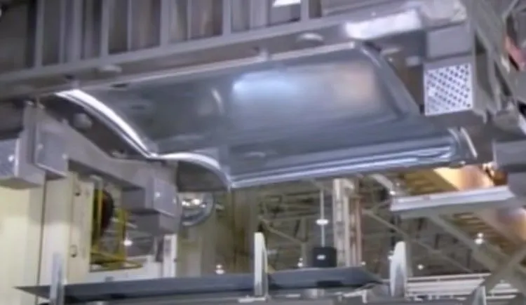
Fig:4-Hydraulic Press
3. After the reuired part is obtained, the excess metal is trimmed and holes and slots are created for mounting points.
4. A robotic arm places the mastic points where the outer and inner panel of the back door is to be joined.
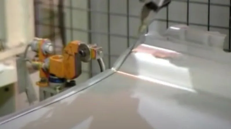
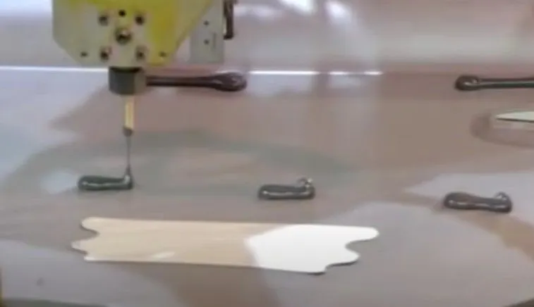
Fig:5-Mastic sealant
5. The outer and the inner panel is joined by a process called Hemming in which the outer pannel contour is folded and rolled over the inner panel of the back door.
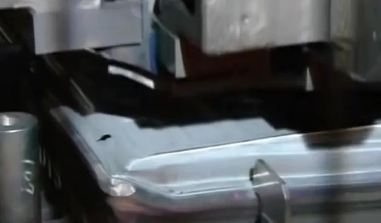
Fig:6-Hemming
6. Finally, the Back door is painted and attached to the car followed by inspection.

Fig:7-Final Inspection
Types of Back doors:
Based on Orientation:
1. Top mounted:
These back doors are most commonly used back doors in Hatch back cars. The hinge axis of these back doors is horizontal anf the opening angle is measured with respect to vertical. The back door is hinged to the roof of the automobile.
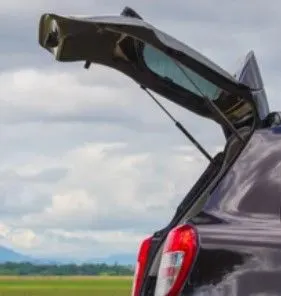
Fig:8-Top mounted
2. Bottom mounted:
The hinge axis of the bottom mounted back door is positioned at the lower side of the trunk or the storage compartment.
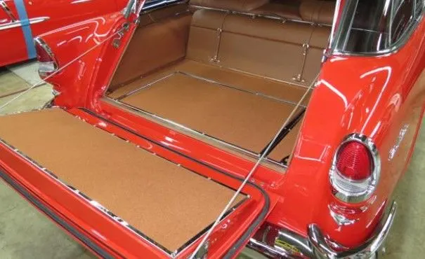
Fig:9-Bottom mounted
3. Side mounted:
These back doors have a verticallly positioned hinge axis. The opening angle is measured with respect to the length of the car.
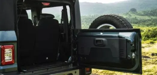
Fig:10-Side mounted
Based on opening mechanism:
1. Gas stay mechanism:
These are the manual back doors which are assisted by a gas stay. Human effort is required to use these types of back doors which are generally top mounted.
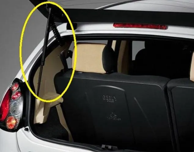
Fig:11-Gas stay mechanism
A Gas stay is a device which is used to keep the back door in an open position by means of a lever and an actuator. The addition of gas stay increases the weight hence reinforcements are added to increase its strength locally.
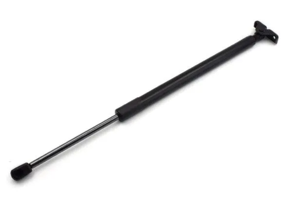
Fig:12-Gas stay
2. Power assisted mechanism:
The Power assisted mechanism used a power liftgate. A power liftgate opens and closes automatically when activated by key fob, which is a button inside the car, or by waving the foot below the bumper on select vehicles. Human effort is minimized in these back doors.It is a motorized hatch that opens and closes electronically.

Fig:13-Foot waving mechanism
Experimental Tests:
These tests are performed by Manufactureres or testing companies to formulate a report which should be passed by the regulation norms. These tests are done to calculate the star rating of the car.
1. Bend Test:
The Bend test is done to find the bending strength, stiffness and other parameters of the manufactured component.
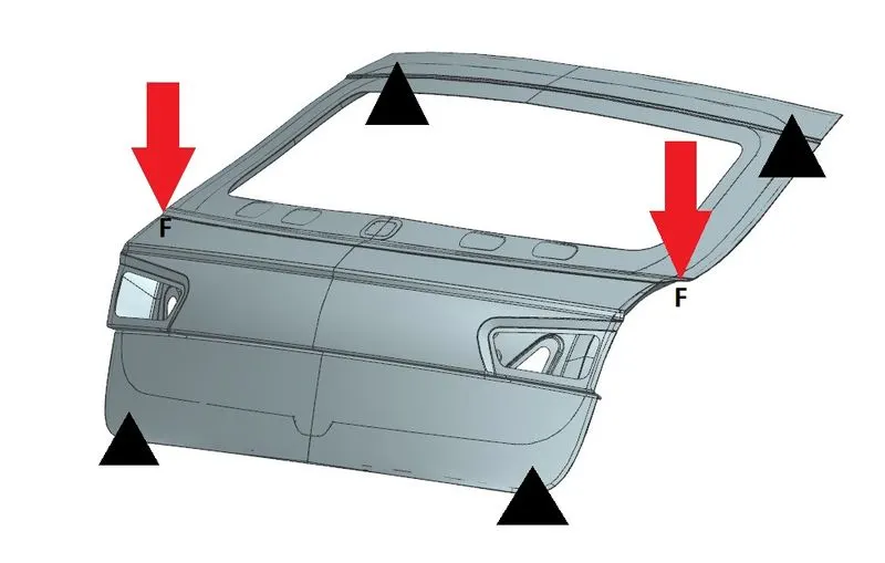
Fig:14-Bend test
2. Torsion Test:
The torsion test is performed by twisting the manufactured component and is essential in finding the torsional shear stress, maximum value of torque, shear modulus and the breaking angle of the back door.
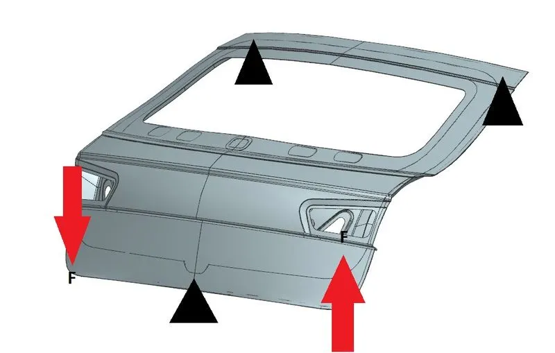
Fig:15-Torsrion test
3. Abusive Test:
The performance of the door assembly when subjected to an abuse load of sag and over opening is one such perceived quality indicator which gives the customer the first impression about the engineering and build quality of the vehicle.
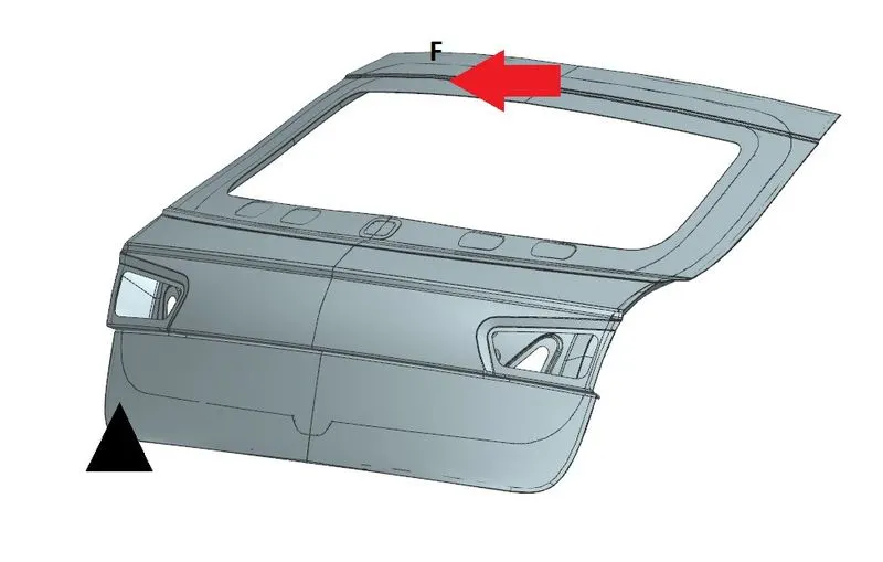
Fig:16-Abusive test
4. Dent test:
In this test the robotic arms produce a dent on the car and the car model and material is optimized to reduce the time taken by the door to come back to its initial position after the load is removed.
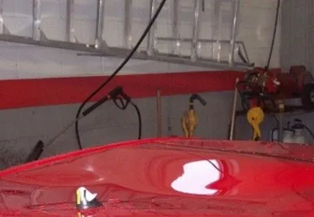
Fig:17-Dent test
5. Assembly load case:
In this test the effect of increasing the weight of the door assembly is studied on the overall performance of the automobile.
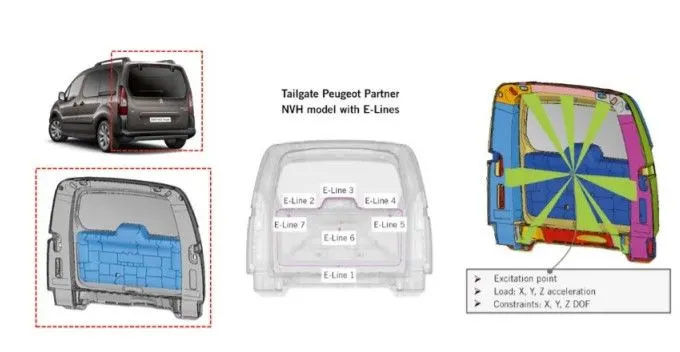
Fig:18-Assembly load case
6. Endurance test:
In this test the door is opened and closed for several cycles. It is used to study the effect of impact loading due the sudden impact of closing the back door.
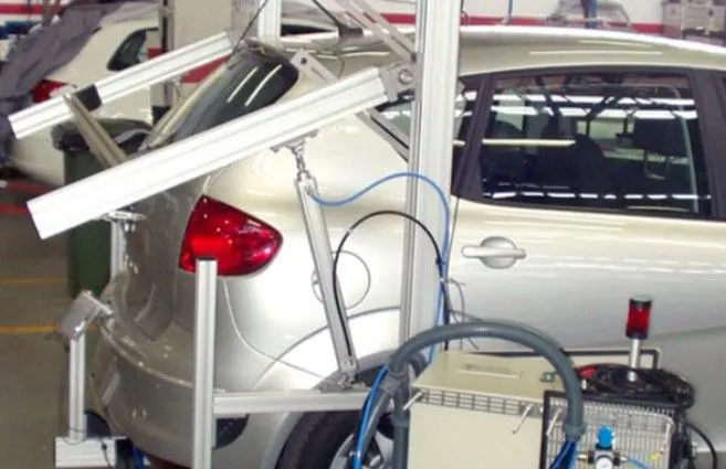
Fig:19-Endurance test
Result:
After performing all the tests it is observed that the force and energy dissipation is effective if a V or Y shaped emboss is given on the door.
Back door Design:
Input Data:
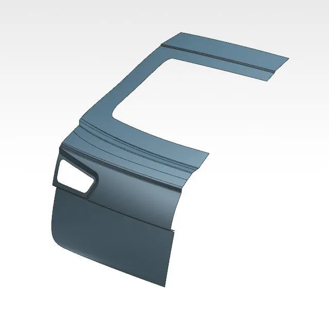
Fig:20-Styling data of the outer panel
Backdoor Design in NX CAD:
The components designed in this project are Outer panel, Inner panel and Reinforcements for Hinges, Wiper motor, Striker and Gas stay.
1. Inner Panel:
The inner panel of the back door assembly is that component which is positioned between the outer panel and the storage compartment of the car. Its main function is to improve the strength of the door. It has mounting points for the positioning of hinges, striker, gas stay and wiper motor at the rear side of the automobile.
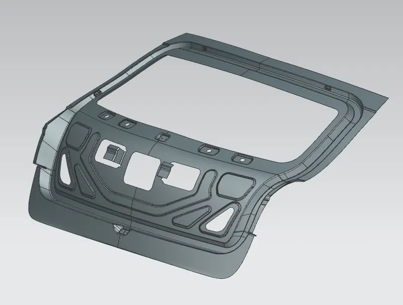
Fig:21-Inner Panel designed in NX CAD
Force and Energy dissipation criteria:
As mentioned in the experimental tests, the inner panel is provided a V emboss such that the energy generated duing the rear impact is dissipated sideways. This helps in reducing the effect of the collision and protects the passengers from severe injuries.
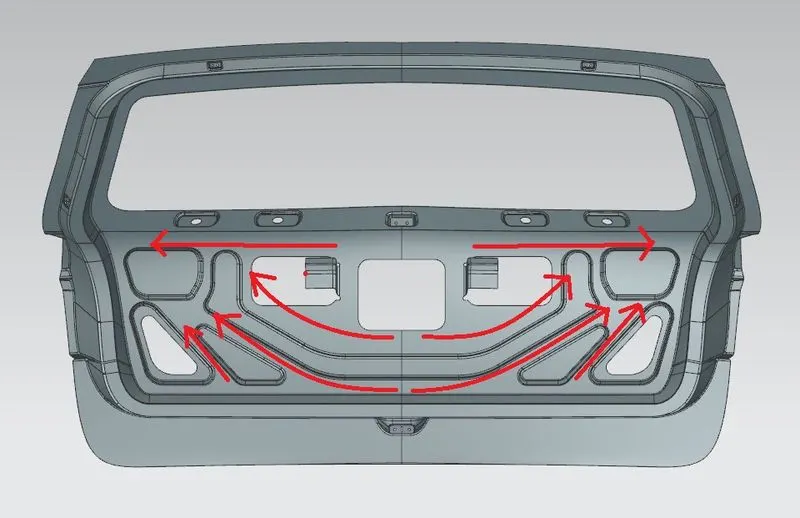
Fig:22-Energy dissipaton
The embosses helps in increasing the strength of the sheet metal components. The embosses are oriented in such a way that the force is dissipated outwards. The cut outs are provided for fixing the lamps. The inner panel is given a thickness of 0.75 mm.
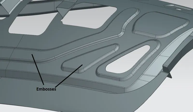
Fig:23-Embosses in the inner panel
Embosses are also provided to mount other components of the back door assembly. A Diabolo emboss is provided for the mounting of the gas stay.
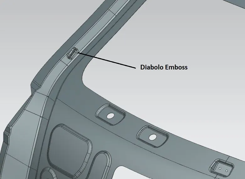
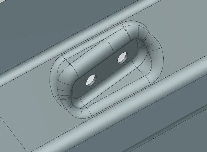
Fig:24-Diabolo emboss for Gas stay
Hinge embosses are created for the mouting of hinges between roof and back door.
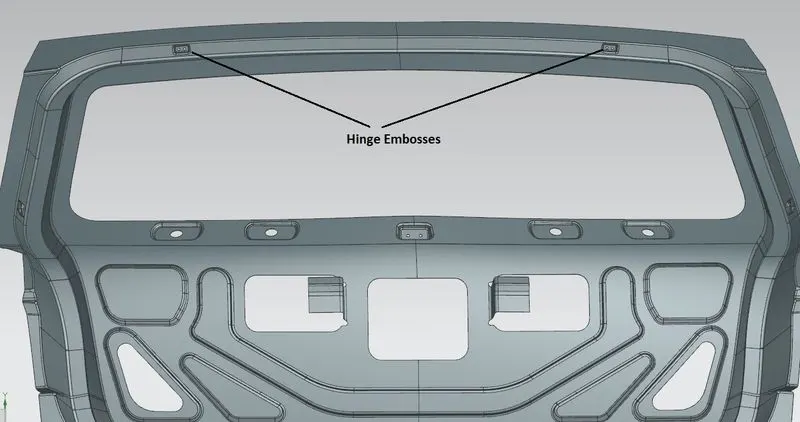
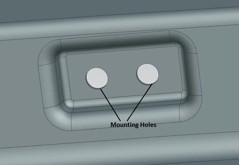
Fig:25-Hinge embosses
An assitional emboss is provided for placing the wiper motor components inside the inner panel.
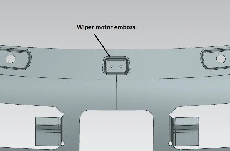
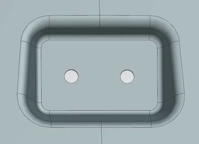
Fig:26-Wiper motor emboss
Latch Trajectory:
It is a circle which is sketched with center as the hinge axis. The hinge axis is an axis parallel to x-axis and passing through the hinge joints. This trajectory is used to create the striker emboss for mounting of the Latch-Striker on the inner panel.
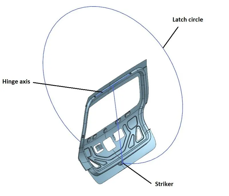
Fig:27-Latch Trajectory
The Tangent drawn to the circle at the lower end should be perpendicular to the base of the latch to ensure correct opening and closing of the back door. The striker emboss is created based on the latch trajectory.
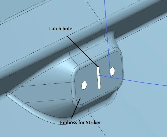
Fig:28-Striker emboss
Flanges are provided in the inner panel so that mastic sealents are used to to attach it with the outer panel. The sealant is in the form of fluid paste which eventually hadens in a hot bath and joins both the panels.
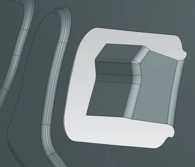
Fig:29-Joining flange
A clearance of 5 mm between this flange and outer panel is provided for application of mastic paste.
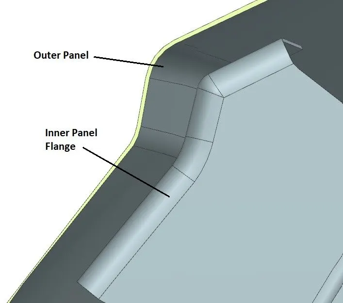
Fig:30-Section view for joining flange
Side flanges are provided for attaching the upper and outer part of the outer panel with the inner panel.
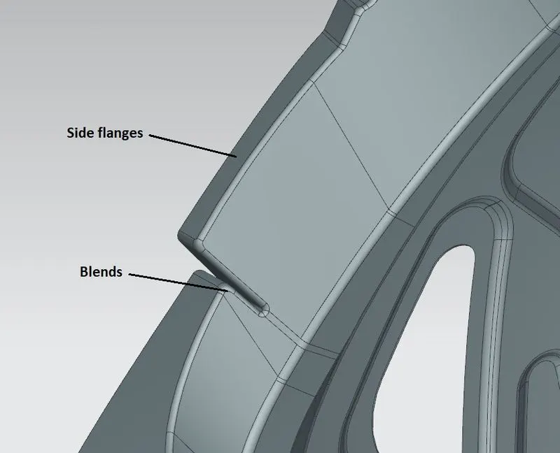
Fig:31-Joining flanges
A rectangular cutout is provided to access the wiper motor in the inner panel.
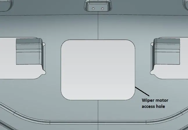
Fig:32-Wiper motor access hole
2. Outer Panel:
The outer panel is the part of the door which can be seen from outside. It helps in improving the aesthetic of the car and has a space for mounting the windshield considering the rear visibility criteria. The outer panel is manufactured into two parts namely Upper outer panel and the lower outer panel. The thickness of the outer panel and the inner panel is 0.75 mm.
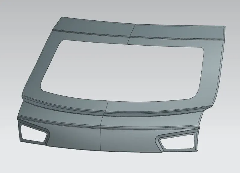
Fig:33-Upper Outer Panel
This panel also has cutouts for mounting the rear lamps on the automobile.
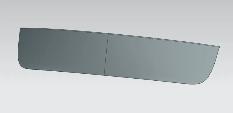
Fig:34-Lower Outer Panel
Hemming:
It is a process usedin Automobile industries to join the sheet metal components together. For the back door assembly, the outer panel and the inner panel are joined by hemming. It is done bending the outer panel over the inner panel with the help of rollers and robotic arms. Rollers makes several passes to join both the panels.
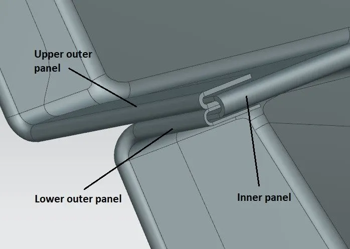
Fig:35-Hemming
Relief is provided on the outer panel to ease out the hemming process and to reduce the stress concentrations.
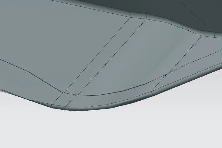
Fig:36-Hemming relief
3. Reinforcements:
When the components like hinges, striker, gas stay and wiper motor are addeed to the door assembly, the strength of the door is lowered due to addition of extra weight. To compensate for this loss, extra material called reinforcement is added to the inner panel of the back door. Commonly used reinforcement material is Glass fibre which helps in lowering noise, vibration and harshness problems.
A. Hinge reinforcement:
This material is added below the hinges on the inner panel to improve the local strength around the hinge assembly. The thickness of this reinforcement is 1.5 mm.
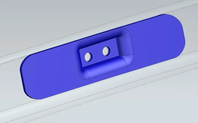
Fig:37-Hinge reinforcement
2. Gas stay reinforcement:
This reinforcement material is used for increasing local strength around the gas stay. Its thickness is 1.5 mm.
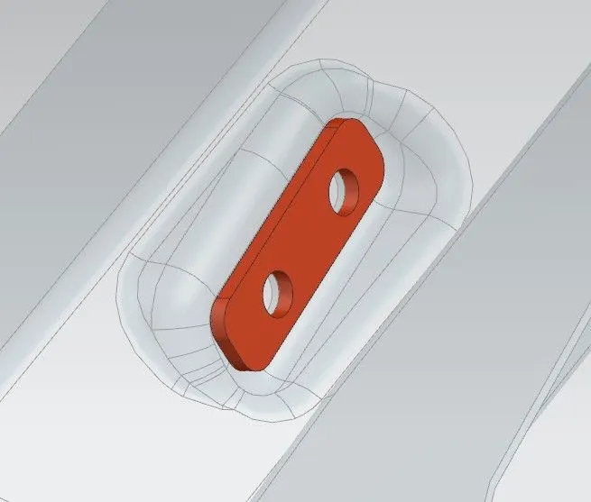
Fig:38-Gas stay reinforcement
3. Wiper motor reinforcement:
The thickness of the wiper motor reinforcement is 1.5 mm.
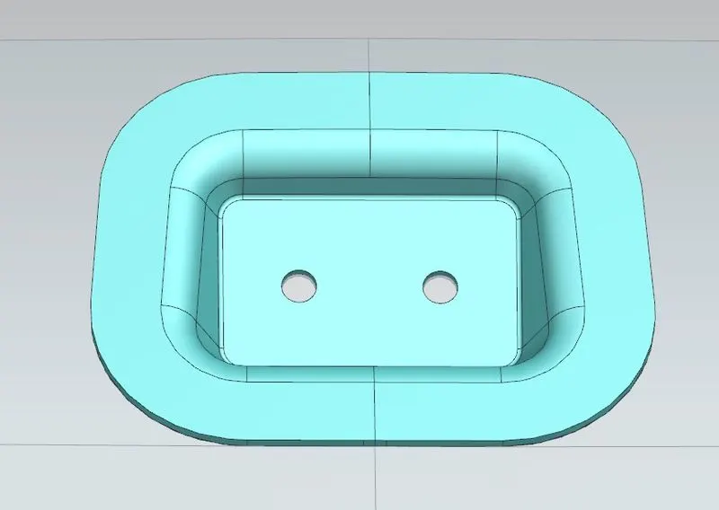
Fig:39-Wiper motor reinforcement
4. Striker reinforcement:
This is placed on the perpendicular striker emboss for increaing the local strength. It has to bear the impact load produced during the closing of the back door. Its thickness is 1.5 mm.
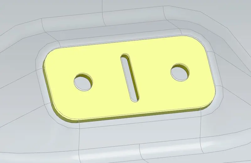
Fig:40-Striker reinforcement
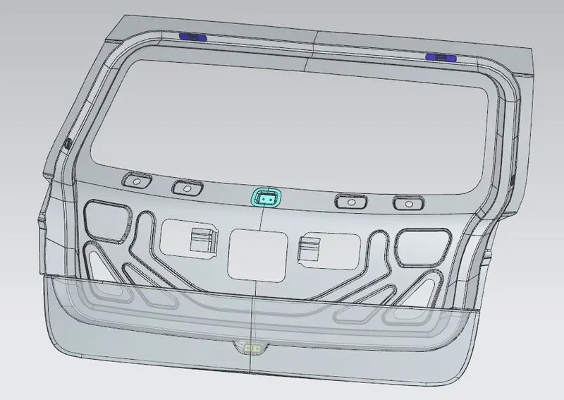
Fig:41-Layout of the reinforcements in the inner panel
Final assembly:
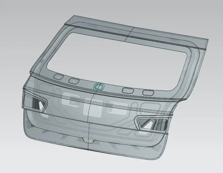
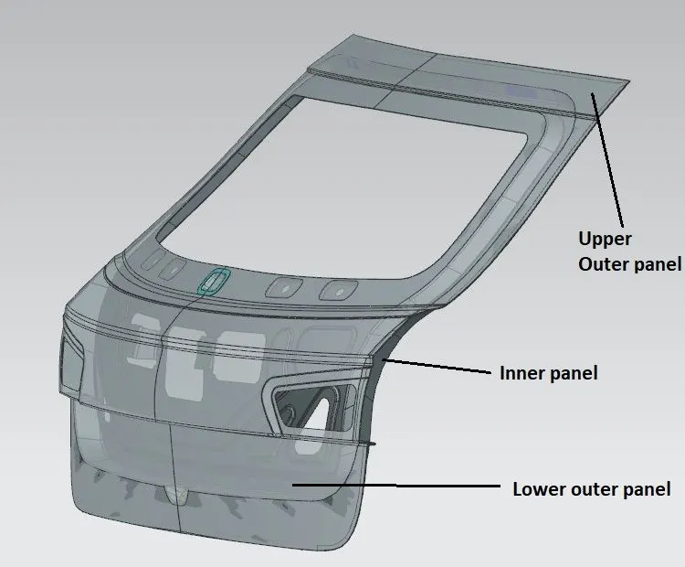
Fig:42-Back door assembly in NX CAD
Draft Analysis:
This analysis is used to find the producibility of the sheet metal components. It is ensured that there are no negative drafts. If there is negative draft or an angle of less than 5 degrees from the tooling direction then the stamping tool will get stuck inside the sheet metal blank. The angle should be greater than 5 degrees for effective sheet metal manufacturing.
Tooling direction:
It is the axis along which the hydraulic stamping machine travels and produces the required component from the sheet metal blank.
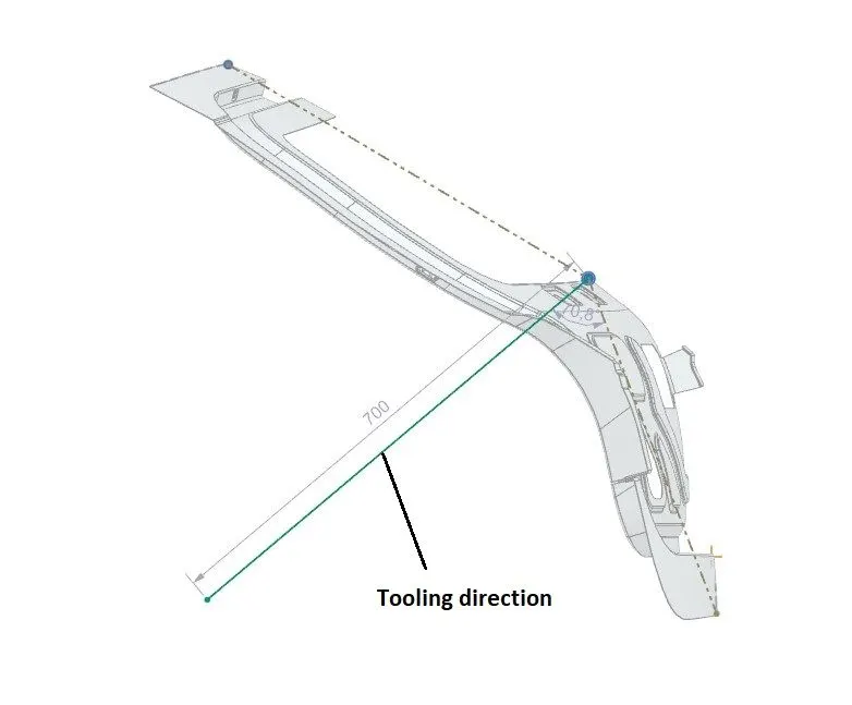
Fig:43-Tooling axis
The producibility of the inner panel is determined by using the tooling axis as vector in NX CAD.
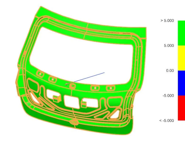
Fig:44-Draft analysis
Result:
Green colour depicts that the part can be manufactured effectively by using the blue axis as the tooling direction.
Section Inertia Analysis:
This analysis is used to find the parameters like moment of inertia, center of gravity, circumference and area in NX CAD. The moment of inertia is a measure of strength of the manufactured component. The Section modulus is used to analyze the strength of the sheet metal.
Side crash analysis:
For side crash the the side sketch of the Door assembly is used which is projected on the XY Plane. The holes and the cutouts of the windshield glass are modified to make it a closed sketch for analysis.
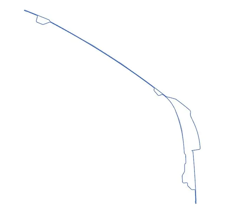
Fig:45-Sketch for side crash
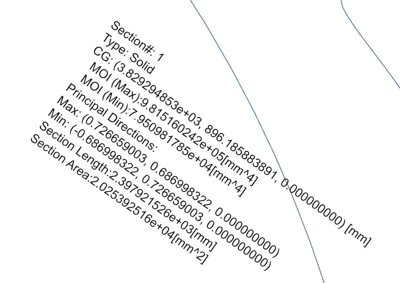
Fig:46-Section Inertia Result
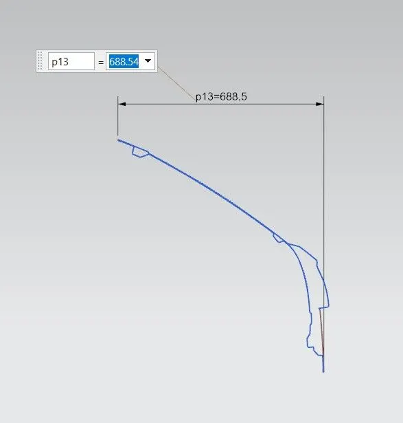
Fig:47-Length of the section
The minimum Moment of Inertia, I=7.95*e^4 mm^4
The length of the section, L=688.54 mm
The section modulus is given by, S=I/0.5L=7.95*e^4/688.54= 115.46 mm^3.
Rear crash analysis:
For rear crash, the ineterrsection sketch produced by the outer-inner panel and a plane passing midway between the extremities is used.
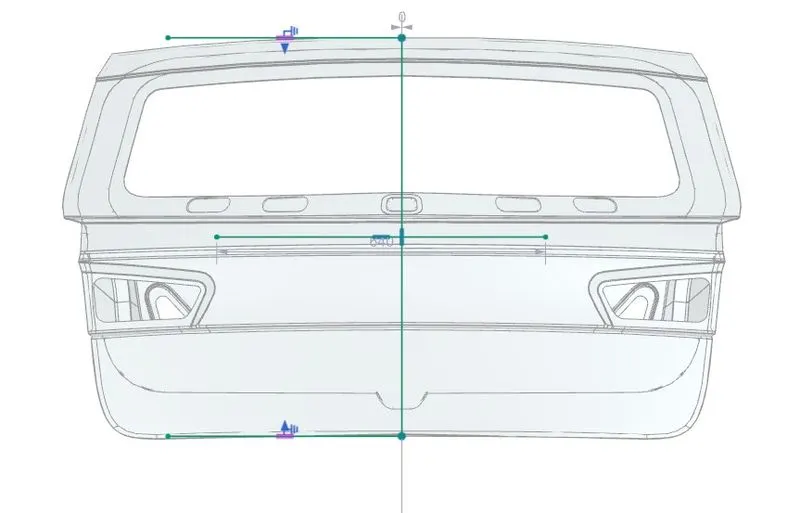
Fig:48-Horizontal centerline
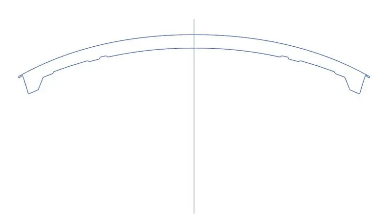
Fig:49-Sketch for rear crash
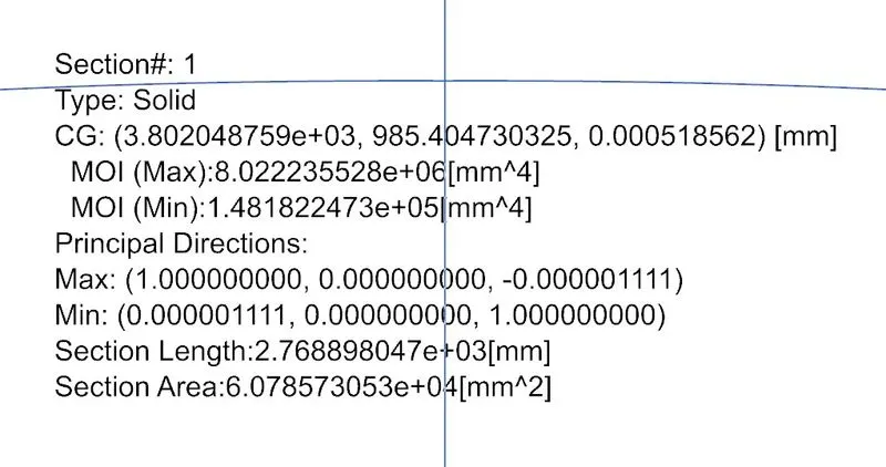
Fig:50-Section Inertia Result
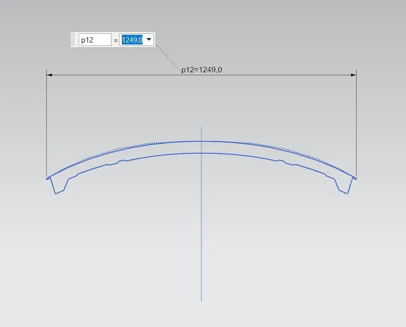
Fig:51-Length of the section
The minimum moment of inertia, I=1.48*e^5 mm^4
Length of the section, L=1249 mm
Section modulus, S=I/0.5*L=188.49 mm^3
Result:
The strength of the components were determined using the section modulus. The strength can be increased further by increasing the overall thickness formed by the contours of outer and the inner panel. The outer panel bulging can be increased such that enough space is there for the storage compartment.
Back door in SolidWorks:
The final assembly was exported as a STEP file. These are the realistic views in SolidWorks.
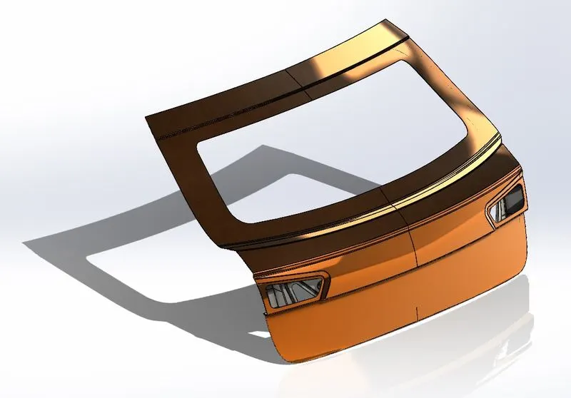
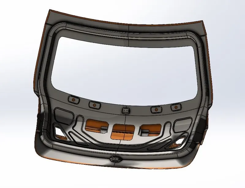
Fig:52-Back door in SolidWorks
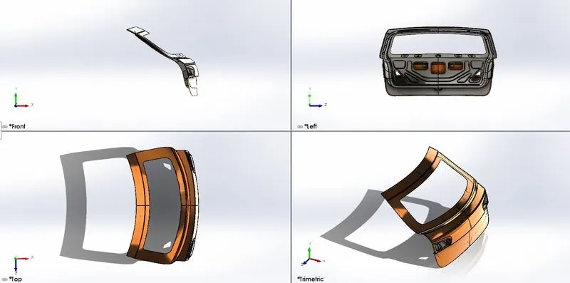
Fig:53-Four view display
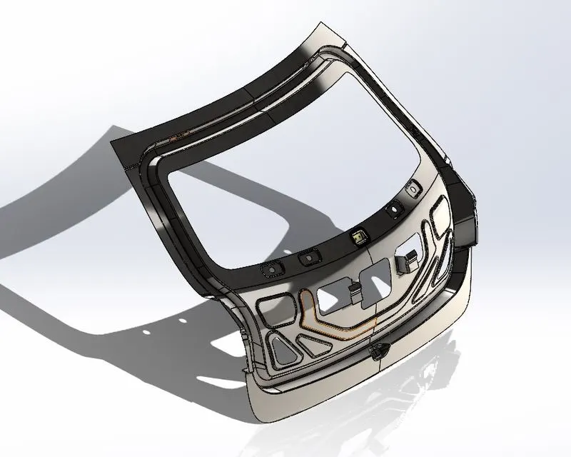
Fig:54-Inner panel and reinforcements
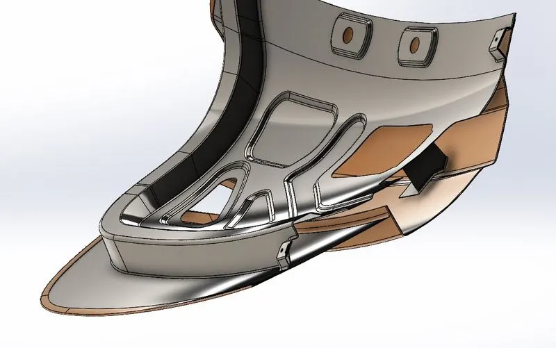
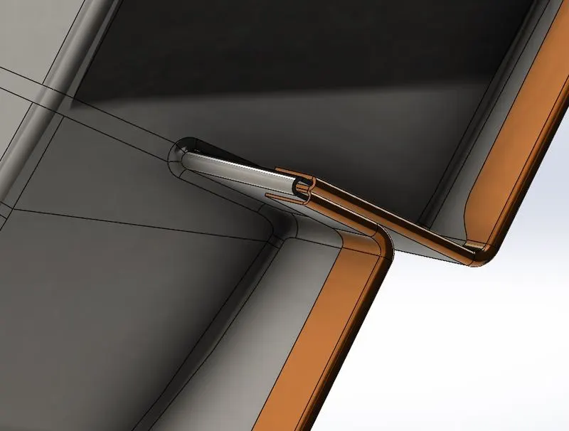
Fig:55-Section view and hemming snap
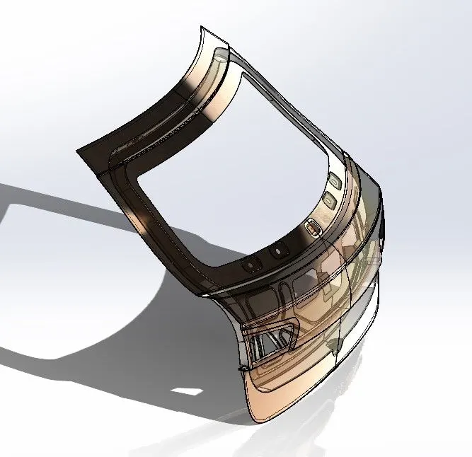
Fig:56-Inner view of the back door
Conclusion:
The Back door was designed in NX CAD considering the design standards and draft analysis and section inertia analysis were performed to determine the effectiveness of the design.