Design of backdoor
AIM
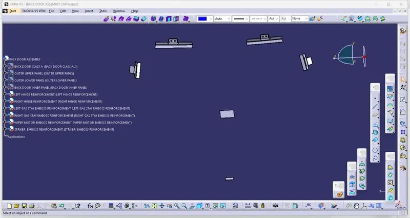
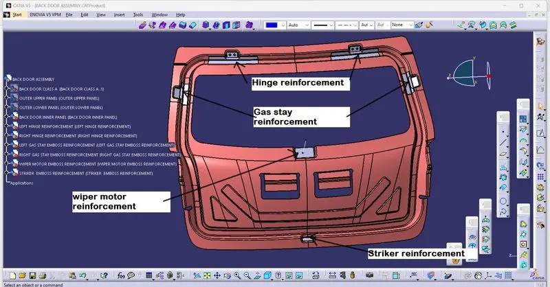
To create the back door design with necessary reinforcement and embosses (Hinge, gas stay, wiper motor, striker) using given class A surface and to do draft analysis for the parts.
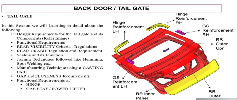
PARTS IN BACK DOOR
Back door is a closure used for access the boot spce of the car and it is also used to protect forign particle to enter into the car. It consist of two major parts inner and outer panel.
It is also protect passenger while car subjected to rear crash by directing forces towards hinges and outer panel of the car. Back door has to crumple and absorb energy. It should not be rigid when it is subjected to crash.
DESIGN CONSIDERATIONS
1.Opening angle
Opening angle of back door is decided by the average height of the people in the country. It will vary country to country based on the height of the people.
we have to make sure that the opening angle is more to access boot space comfortable.
Position of gas stay plays a big role in deciding the opening angle. if the gas stay placed near to the top flange of the back door opening angle will be more. By changing the position of the gas stay we can change the opening angle.
2.Trajectory of the back door
Path followed by an entity is generally called as trajectory. In back door design, path followed by a point on a striker is called as trajectory. The trajectory has to be proper to ensure proper locking of latch and striker.
Trajectory has to be proper to ensure proper locking of latch and striker while opening and closing of back door.
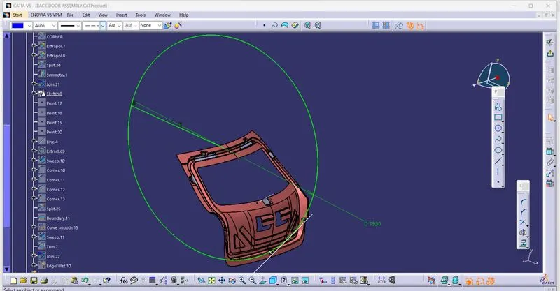
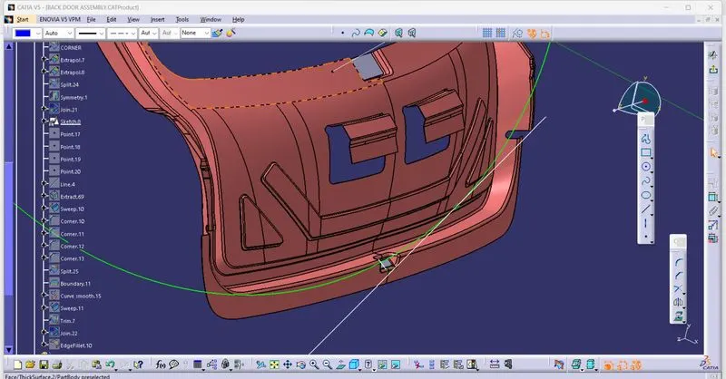
Striker Emboss surface has to be perpendicular to the tangent line drawn on the trajectory to ensure the proper lock between striker and latch.
3. Position of embosses
Reason for giving embosses:
1. To resist bending of the sheet metal is the primary reason for embosses.
2. To direct the forces based on the application we need. In back door inner panel design embosses are created in such a way that it has to direct the forces towards hinges and outer panel of the body, this helps to reduce the impact towards passengers.
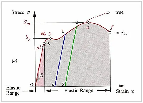
When the sheet metal is strained to any point upto the point marked pl , the stress is proportional to strain and if the stress is known the strain can be computed and vice versa, from the Youngs Modulus which is the slope of this curve. When the load is released it bounces back to original state and there is no permanent strain.
In the region between pl and el/y, the sheet metal is still elastic but stress and strain are not proportional. This represents the nonlinear elastic region. Let us assume the sheet is strained to the point A. Still, as it is elastic, when the load is released, the strain is released and once again there is no permanent strain.
Here pl is the proportionality limit, el is the elastic limit and y is the yield point.
Beyond the point denoted as el or y which represent the elastic limit or yield point, the sheet metal ceases to be elastic and enters the plastic region. When it is loaded to the point lets say point 1, and when the load is released, it follows the path shown in Blue colour. So there is a permanent set given by ox. When it is again loaded it follows the blue line and yields when the stress reaches the point 1. It is to be noticed that this stress is higher than the earlier stress,el/y, at which it started to yield. It looks as if the member has become stronger. Now if it sheet metal is loaded to a point, say 2 then the yield point once again shifts higher than the point 1. The metal when strained appears to become stronger and this region is referred to as the strain hardening region.
So in all the above applications as it is strained during the embossing process to a point beyond yield point the member appears to have greater strength thus giving it the capability to withstand higher loads without deformation.
Now stiffness of a structure is a property by virtue of which it resists deformation. This depends not only on the Material property ( E,or G) but also on the cross section dimensions. By changing the cross section there will be added stiffness thus making the member more resistant to lateral deformation.
Hinge embosses
Initially hinge embosses are given and then i took two holes for nut and bolt and through the center of the holes i draw a line and this line will be parallel to the hinge axis. Since hinge is not given to me. I took this line as hinge axis, with the help of the hinge axis i drawn striker emboss.
Gas stay embosses
Gas stay emboss are given near to the top flange of the inner panel to ensure maximum opening angle. Here i added bigger reinforcement with large surface area, because this place is going to subjected with more load.
Wiper motor emboss
Emboss given in a place where we install wiper motor. Small reinforcement is given in this emboss area, because this area is not going to be loaded often.
Striker emboss
Embossing is an auxillary sheet metal operation that is performed, using male and matching female dies, to increase the strength and also the stiffness.
4. Rear visibility criteria
We have to make sure the position of rear glass should be proper to see what is happening backside.
Position of Rear roof rail aslo playing a big role in rear visibility.
5. Optimizing inner panel for more boot space
We can not drastically increase the space, but we can increase little by changing the inner panel shape and geometry.
Distance between inner and outer pannel plays a huge role in deciding the boot space. we kept 0.2mm space between inner and outer pannel for sealent. Sealent is the adhessive material to connect the sheet metal in place.
I provided 5mm gap for the mastic to avoid the vibration between inner and outer panel of the back door.
FUNCTIONAL REQUIREMENTS
1. Functional requirement says about how parts needs to behave. For back door when it is subjected to rear crash, inner and outer panel should not pass the forces/ impact towads passenger.
2. Back door has to be designed in such a way that it has to crumple and absorb the energy. Embosses are given to direct the forces towards hinges and outer body to protect the passengers.
3. Back door has to be opened with large opening angle to ensure better acessibility of boot space.
4. Sealing flanges are given in inner panel to avoid forign particle to go inside the boot space.
5. Reinforcements are given to increase the strength locally, where it is subjected to more stresses. In back door hinge area is going to be opened and closed often and it contains nut bolt assembly as well. To increase the strength at these places we need to add some extra materials.
6. Corner reliefs are given to remove shrinking and folds of excess material at the bends in the hemming process.
REINFORCEMENTS
1. Reinforcements are given to increase the strength locally, where it is subjected to more stresses. In back door hinge area is going to be opened and closed often and it contains nut bolt assembly as well. To increase the strength at these places we need to add some extra materials.
2. These extra additon of materials will provide more strength than the previous situation.
3. If we go for Aluminium we do not need to add extra parts. We can increase thickness locally by casting. This is one of the major advantage of the aluminium and it is also less weight.
4. If we go for steel we can not vary thickness locally we nee to add some parts seperately for reinforcement. Weight of the part is also going to varied.
5. Weight of the steel inner panel is 4.7Kg higher than the aluminium even with the higher thickness of aluminium. When it comes to cost aluminium is way costlier than steel.
Based on the money, weight of the material and manufacturing process company will opt for different materials
| S.NO | steel | Aluminium |
| Parts | Parts are stamped | Parts are casted |
| Reinforcement | Necessary | Can be neglected by varying thickness locally |
| Thickness | Constant | Can be varied |
| Components | More components, because thickness can not be varried | Back door can be made as one single part |
| Weight | More weight because of high density | Less weight because of less density compare with steel |
| Cost | Less in Cost As compared to Al | More As compared to Steel |
DRAFT ANALYSIS
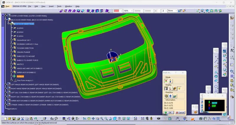
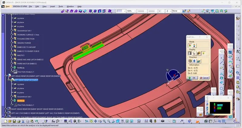
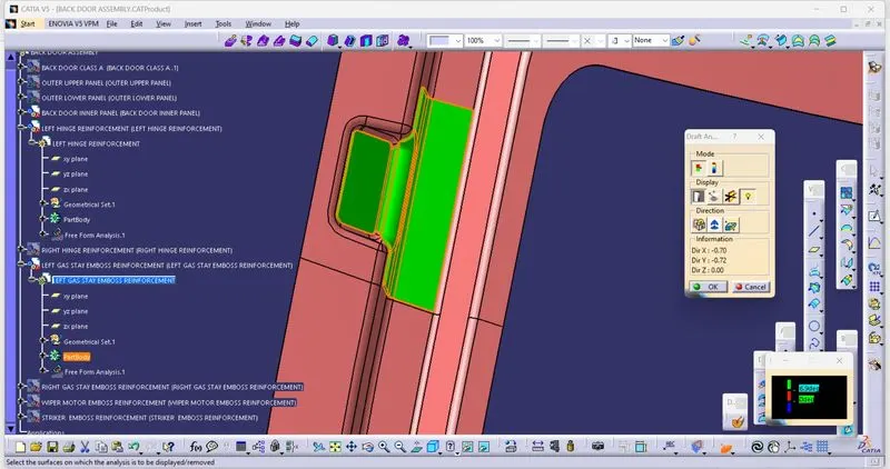
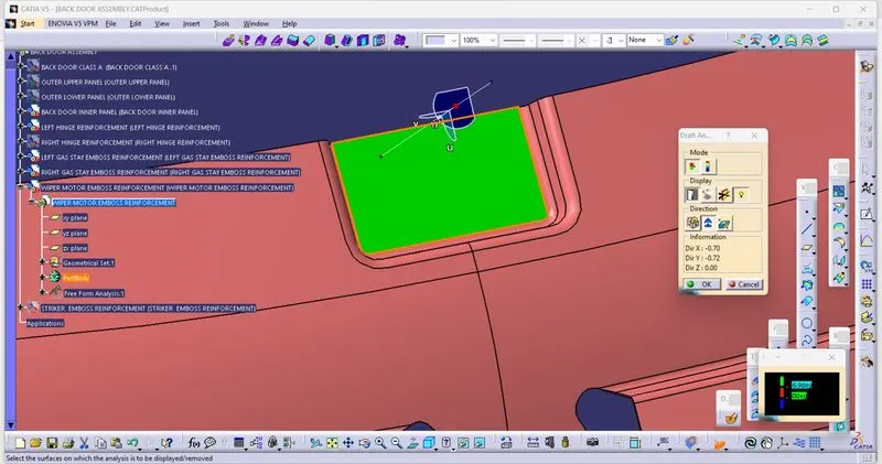
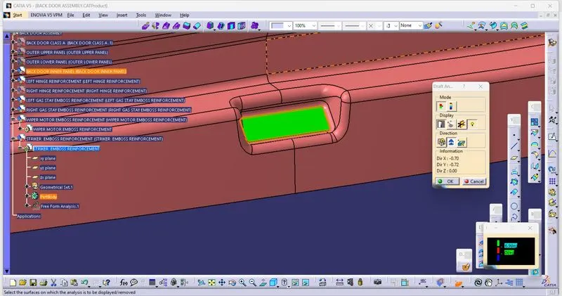
1.Draft angle is given to the surfaces which are parallel to the tooling axis to ensure the ease removal of tool from the part or ease removal of part from the tool.
2. Draft analysis is given to ensure that whether the part is produceble or not. In this case i have created the models with minimum of 7 degee of draft angle.
3. If inner panel clears the draft angle, reinforcements will also be cleared because reinforcements are extracted from the inner panel.
INNER PANEL
LEFT HINGE REINFORCEMENT
LEFT GAS STAY REINFORCEMENT
WIPER MOTOR REINFORCEMENT
STRIKER REINFORCEMENT
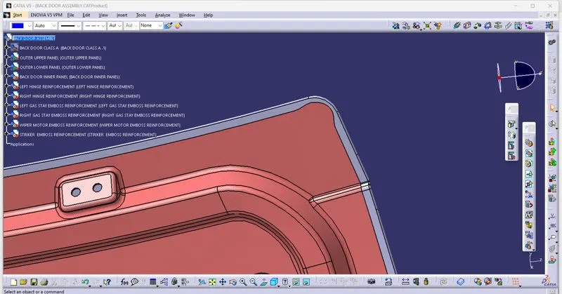
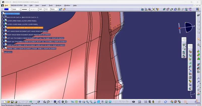
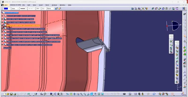
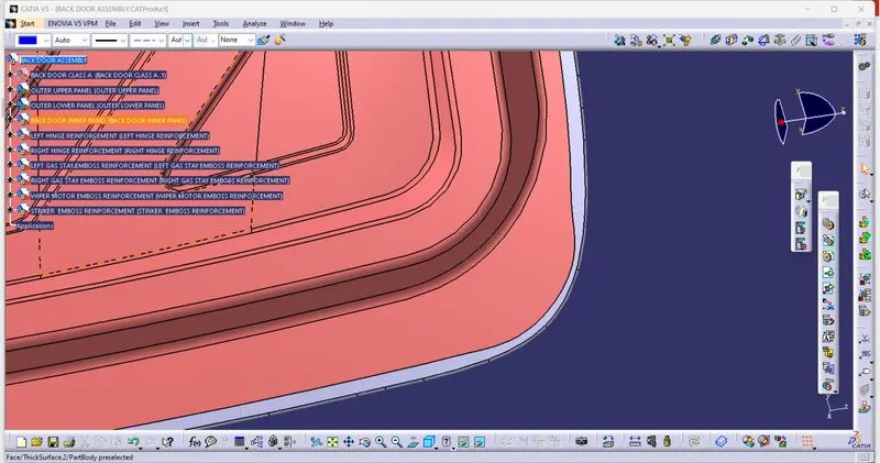
Corner relief
Corner reliefs are given to remove shrinking and folds of excess material at the bends in the hemming process.
Bend relief is one of those small details in a bent part that’s easily overlooked. In parts where it’s required, leaving it out can at best cause unwanted tearing.
MANUFACTURING TECHNIQUE
1. Deep drawing
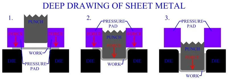
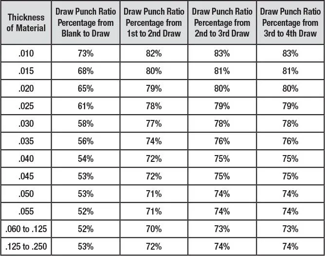
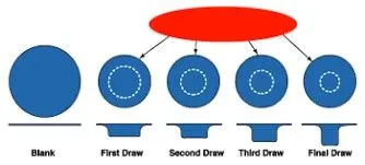
Deep drawing is a sheet metal forming process in which a sheet metal blank is radially drawn into a forming die by the mechanical action of a punch. It is thus a shape transformation process with material retention. The process is considered "deep" drawing when the depth of the drawn part exceeds its diameter. This is achieved by redrawing the part through a series of dies.
DRAW RATIO
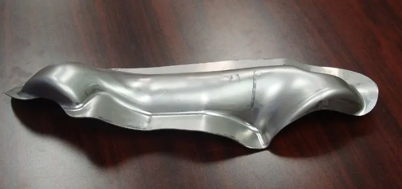
complex deep drawing part
2. Hemming
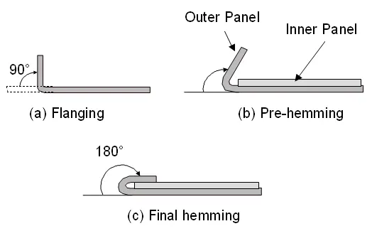
Hemming is the process of connecting two or more parts without disturbing the external surface quality.
Hemming is a sheet metal forming process in which sheets are joined by bending it to 180°. Automotive body panels and automotive parts such as deck-lids, trunk-lids, doors, hoods and tailgates are formed by hemming process.
3. Bending
EDGE BENDING

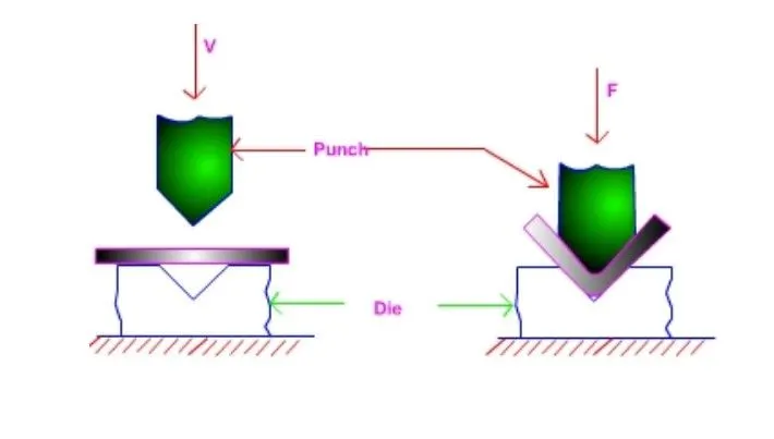
Bending of sheets and plates is widely used in forming parts such ascorrugations, flanges, etc. Bending is a forming operation in which a sheet metalis subjected to bending stress thereby a flat straight sheet is made into a curved sheet. The sheet gets plastically deformed without change in thickness. Die andpunch are used for bending. If a v shaped die and punch are used, the bending is called v-bending. If the sheet is bent on the edge using a wiping die it is called edge bending. In this process, one end of the sheet is held like a cantilever using a pressure pad and the other end is deformed by a punch which moves vertically down, bending the sheet. Usually, edge bending is done in order to obtain an angle of 90o.
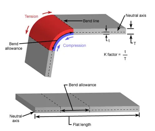
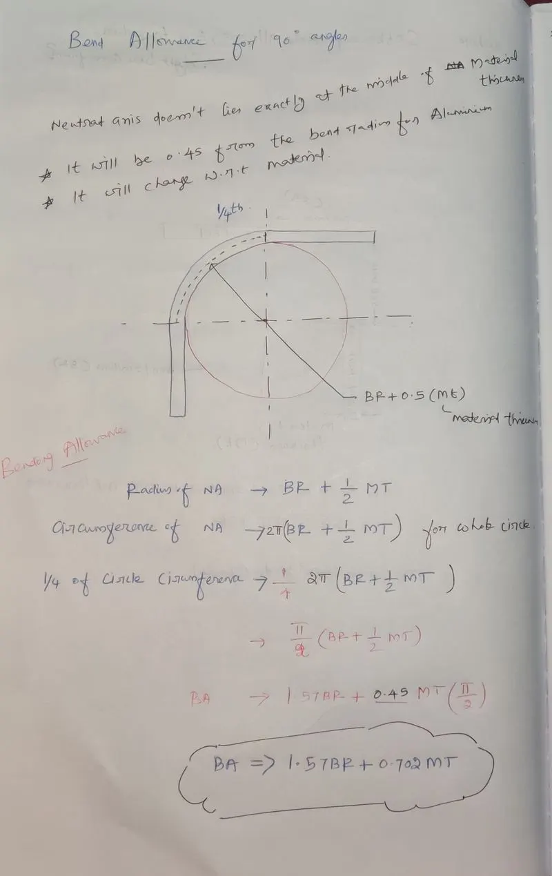
During bending of a strip, the material outward of the neutral axis is subjected to tensile stress. Material inside is subjected to compressive stress. Bend radius R is the radius of curvature of the bent sheet inside the bending. The neutral axis remains at the center of the thickness of the sheet for elastic bending. For plastic
bending, however, the neutral axis shifts towards the inside of the bend. The rate of elongation of outer fibers is greater than the rate of contraction of inner fibers. Therefore, there is a thickness reduction at the bend section.
Conclusion
Back door design successfully done with essential emobosses and reinforcements. Inner panel, outer panel, Reinforcements are clearing the draft angle. All the parts can be practically producible.