Design of backdoor
Automotive Car Back Door Design
Aim:
To create the components of an automotive car back door from the given styling surface.
Abstract:
The given styling surface is a car back door from which the outer panel, the inner panel and the reinforcements are to be created. Draft analysis is to be done for the inner panel to check whether the created component will be suitable for manufacturing. After draft analyzing the component, the remaining parts are to be assembled into a single back door part of a car.
Introduction:
An automotive back door of a car is an access panel for the boot storage or cargo component. The back door consists of parts such as the gas stay for holding the door up while accessing the boot storage, a wiper motor to remove all the rainwater and dust formed on the glass of the back door and a striker with which the door can be locked to the car.
The back door should be designed in such a way that it is light in weight as well as stronger enough to absorb forces from the backside of the car during the time of an impact. The given styling surface for the back door is as shown below.
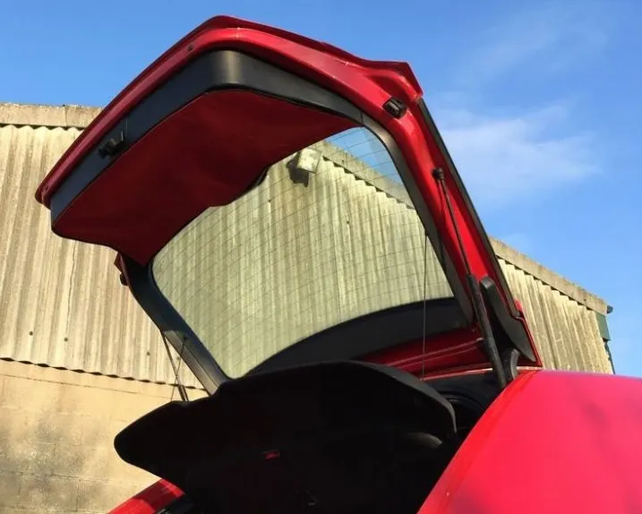
Fig 1: Back Door of the car in real life.
Manufacturing Process:
A sheet metal undergoes the following manufacturing process to form a car door component.
(i) Blanking:
Blanking is a steel manufacturing process in which a flat, geometric shape is created by feeding a sheet metal into a press and die. In this process, the blank is punched out from large sheet metal.
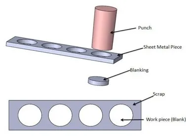
Fig 2: sheet metal blanking.
(ii) Stretch Forming:
Stretch forming is a metal forming process in which a piece of sheet metal is stretched and bent simultaneously over a die to form large contoured parts. Stretch forming is performed on a stretch press, in which a piece of sheet metal is securely gripped along its edges by gripping jaws.
Fig 3: Stretch forming process.
(iii) Punching:
The punching process of sheet metal is to remove the unnecessary or excess sheet metal out from the required sheet metal. The punched out or trimmed metal known as slug is then removed in scrap.
(iv) Deburring:
The deburring process is a smooth finishing process of sheet metal that removes the rough finishing of the sheet metal known as burrs The burrs on a sheet metal are dangerous causing injury and may reduce the life of the component.
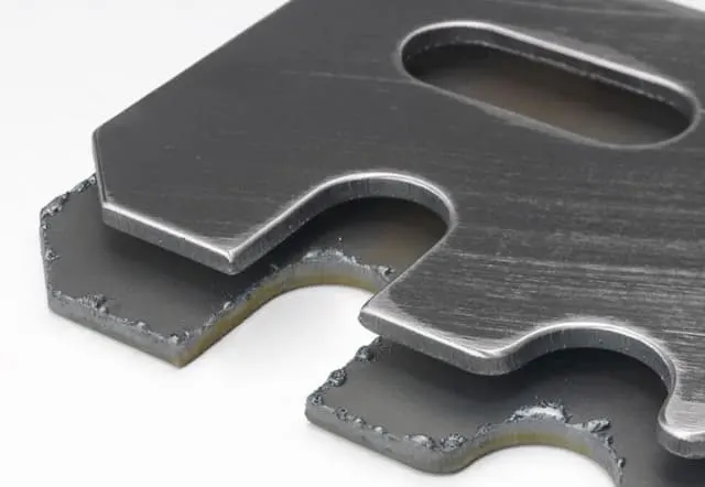
Fig 4: deburring process.
(v) Hemming:
Hemming is a process used in industry to join inner and outer closure panels together (hoods, doors, etc.). It is the process of bending or folding the flange of the outer panel over the inner one. The accuracy of the operation affects significantly the appearance of the car’s outer surfaces and is therefore a critical factor in the final quality of a finished vehicle.
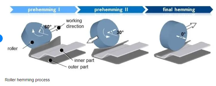
Fig 5: Roller Hemming process
Procedure:
(i) Back Door outer panel:
1. A car outer panel is a sheet metal that is shaped into the required styling surface. Usually, the thickness of the outer and inner panel is approximately 0.75mm. The outer hood is shaped using the hydraulic press and stretch forming process and the edges are bent to hold the inner panel with the help of the hemming process.
2. To design the outer panel, first, check the given styling surface for any kind of errors such as surface imperfections. This is done by thickening the styling surface. If the styling surface is not thickening, then find out the error on the surface and recreate the imperfections. The surface imperfections can be found out by offsetting the styling surface which is helpful in finding out the errors or check for the boundary lines using the boundary option.
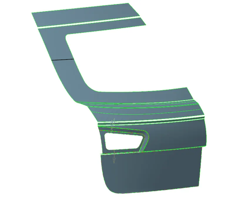
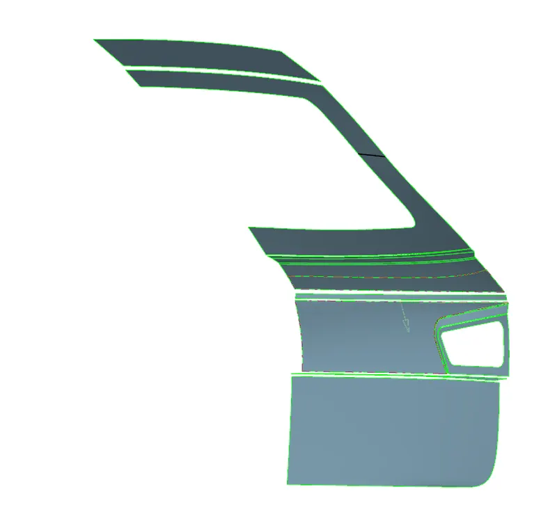
Fig 6: Given back door styling surface outer view. Fig 7: Given back door styling surface inner view.
3. Now the given back door outer panel surface has been designed into two separate parts i.e., the upper panel and the lower panel.
4. Considering the upper panel the hemming is to be created. Since the styling surface has no thickness, hemming is designed for the panel, considering its own thickness after thickening and the inner panel thickness which will be assembled inside the outer panel, and the clearance of 0.2mm is to be maintained between both after assembling the component.
5. Considering the above conditions offset the outer panel with a distance of 1.9mm. Using the parallelism option create a boundary line for the offset surface with a parallel distance of 12mm on the surface as shown below.
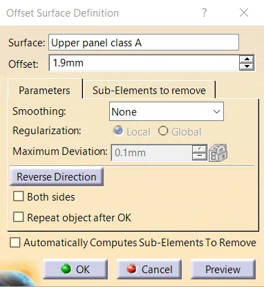
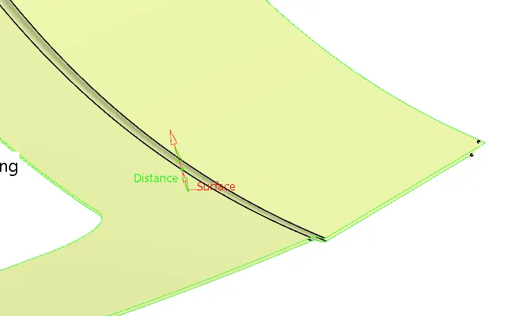
Fig 8: Offset option window. Fig 9: Surface offset direction.
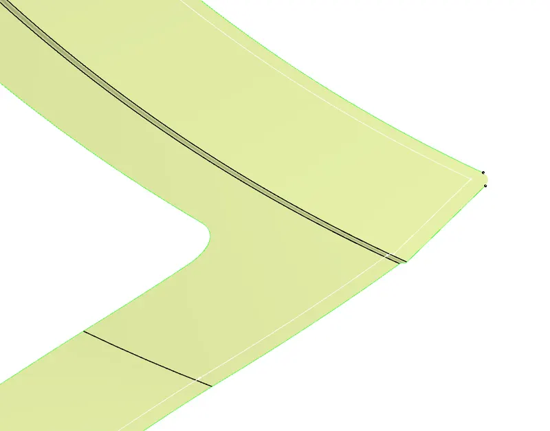
Fig 10: Parallel curve created for splitting purpose.
6. Cut the inner portion of the offset surface with the created parallel line as shown below. Check the split surface for any errors as done on the main outer panel and fix the imperfect surfaces if any.
7. Now the main outer panel surface and the split surfaces are to be joined such that if the sheet metal is folded for the hemming process. Create the outer lines for both the surfaces using multiple extract option such that they act as reference lines for the surfaces. Blend both the surfaces referring to the created boundary lines and the main surfaces as tangent using the option blend or fillet. If this option doesn’t work for the total surface then try splitting the extracted lines into few parts and join the surfaces.
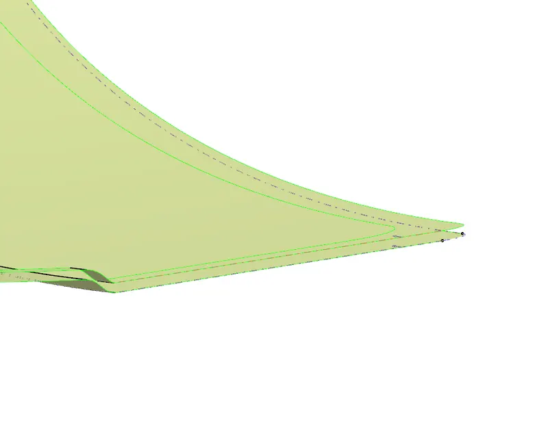
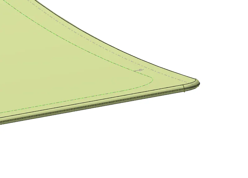
Fig 11: Styling surfaces Fig 12: Created surface for hemming provision.
8. After creating the blend to connect both the surfaces check the created surface using the thicken option with the value of 0.75mm. If the thickening option doesn’t work then check the errors forming on the surface.
9. Now reliefs are to be created near the corners or complicated regions of the hemmed surface as shown below.
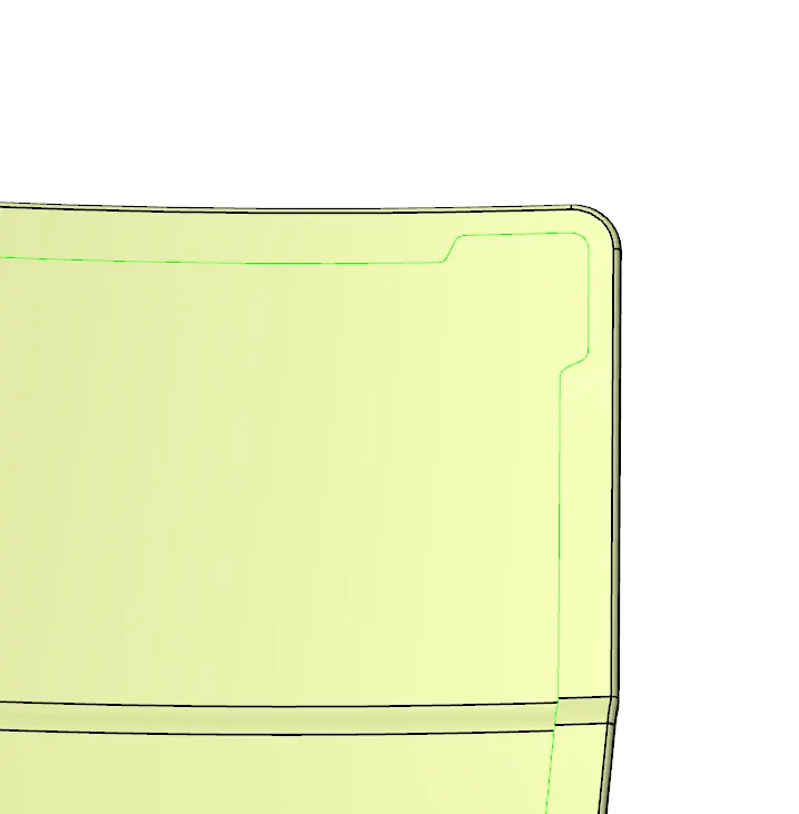
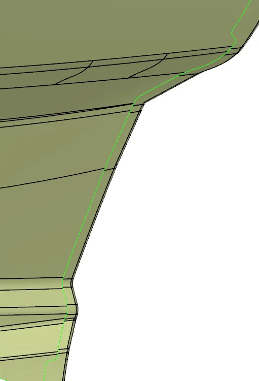
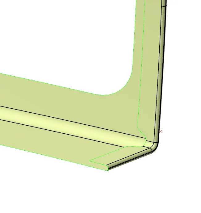
Fig 13, 14 & 15: Provided clearance or reliefs near corners or complicated surfaces.
The reliefs are created during the hemming process to avoid imperfections on the metal during manufacturing.
10. Now after creating one side of the surface mirror reflect the other half using the symmetry option.
11. Join the reflected half to the main half surface. Now thicken the joined component with a thickness of 0.75mm.
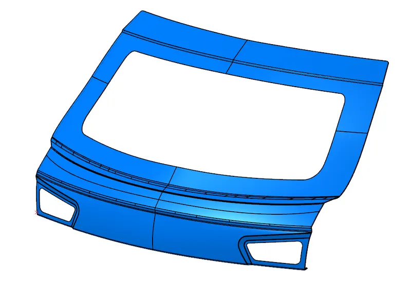
Fig 16: Created back door outer panel from the given styling surface.
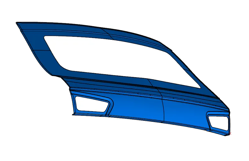
Fig 17: back door outer panel inner side.
12. Similarly, repeat the same process on the lower panel as done above for the upper panel.
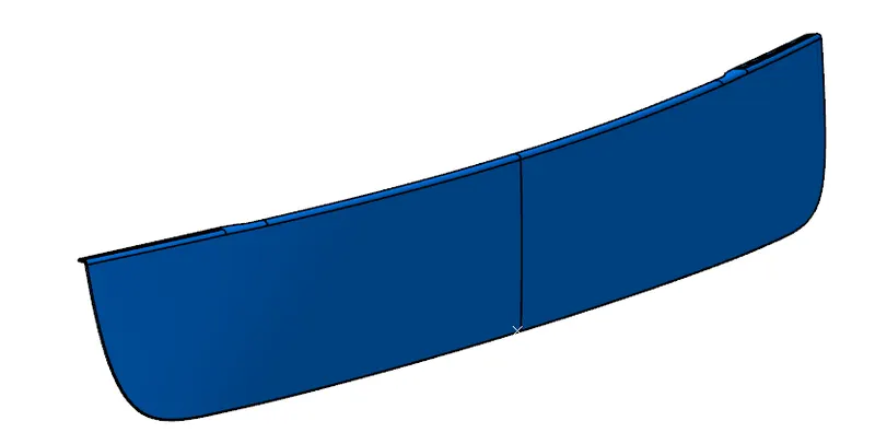
Fig 18: Created back door lower panel from styling surface.
(ii) Back Door Inner Panel:
1. Any inner panel in cars are usually manufactured in such a way it has a patterned holes structure for the following reasons shown below.
(a) To reduce some weight of the component.
(b) A patterned hole structure provides stiffness to the inner panel.
(c) The pattern is designed in such a way that the force acting on the panel in case of an accident will be distributed or directed towards the hinges attached so that to reduce the impact on the passengers inside the cabin.
2. The back door inner panel is manufactured as done for the outer panel and the patterned hole structures are made using a deep drawing or blanking process.
3. To create an inner panel first create a sealing flang with the help of the given styling surface, offset the upper and lower panels styling surfaces towards the inner side up to 25mm and cut the offset surface as shown below with a width of 30mm.
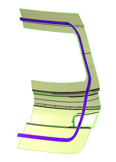
Fig 19: Created sealing flange for the inner panel.
4. Create another offset surfaces with a distance value of 0.95mm towards the inner side.
5. Create surfaces on the edges of the sealing flange on either side with an angle of up to 30mm using the sweep option. The length of the sweep surfaces should be such that it intersects with the second offset surface.
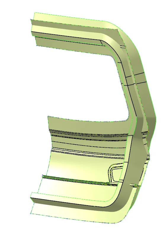
Fig 20: sweep surface from the sealing flange.
6. The glass region of the inner panel should be similar to that of the outer panel as shown below.
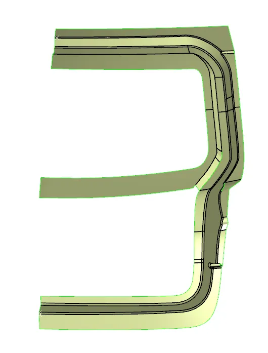
Fig 21: Back door providing glass area.
7. For the lower side of the inner panel, the edge flange of the inner panel should be designed such that it holds both upper and lower outer panels.
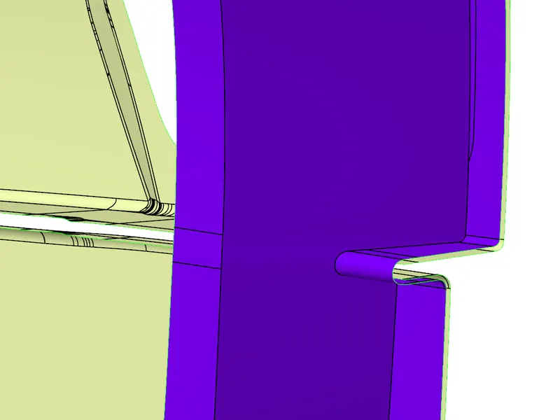
Fig 22: Provision for holding the upper and lower panel.
8. A surface is to be created for the lower region of the inner panel. This is done first by creating the reference lines using the multiple extract option. Using the multi-section surface option create a new surface referring to the lines created and using the contact surfaces as tangents.
9. Join the surfaces and create fillets of the sharp edges with a minimum radius of 5mm. Check the surfaces for any kind of errors or surfaces imperfections by using the thickening option.
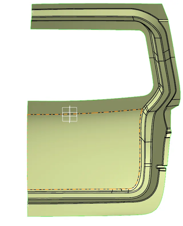
Fig 23: Basic structure of the inner panel.
10. If the surface is thickening without any errors then start creating embossments on the surfaces. Considering the lower side of the panel, the embossments are to be created in such a way that the sheet metal should direct the forces applied towards the outer side when an impact occurs in case of an accident. The embosses are created for strengthening the inner panel. Another importance of an emboss is for providing relief for the sheet metal while manufacturing process. The embossments created for the inner panel are as shown below.
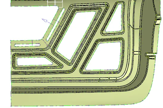
Fig 24: Embossments created at the lower side of the inner panel.
11. Now create embossments near the glass provision area attach the inner and outer panel using mastics and provide space for installing a viper motor as shown below.
12. Create embossments for the provision of assembling the hinges, gas stays and for the striker.
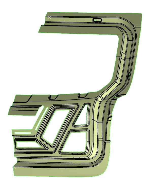
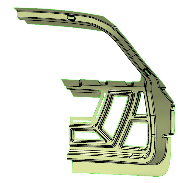
Fig 25 & 26: Created inner panel surface.
13. Create symmetry as done for the upper panel and join it with the original half.
14. Create a sticker provision at the lower part of the inner panel. The sticker provision is given in such a way that it should be easy to lock or unlock the back door by a person according to the positioning of the hinges. Follow the steps mentioned below for creating the sticker provision.
a) Create a reference line connecting the centres of the hinge embossments and create a point at the centre as shown below. The created line is called as trajectory line.
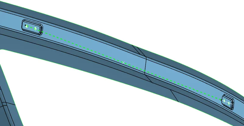
Fig 27: Trajectory line and point.
b) Now create a reference point on the lower edge as shown below.
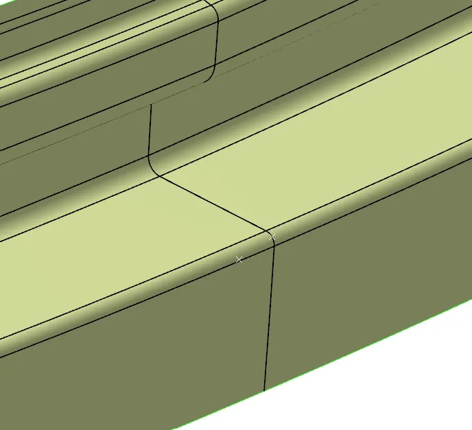
Fig 28: Reference point created for the lower edge
c) Now create a circle with the trajectory point as the centre to the point created at the lower edge of the inner panel. This created circle is called the trajectory curve.
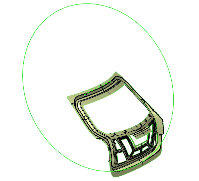
Fig 29: Trajectory curve
d) Now create a provision for the sticker on the edge which is perpendicular to the trajectory curve.
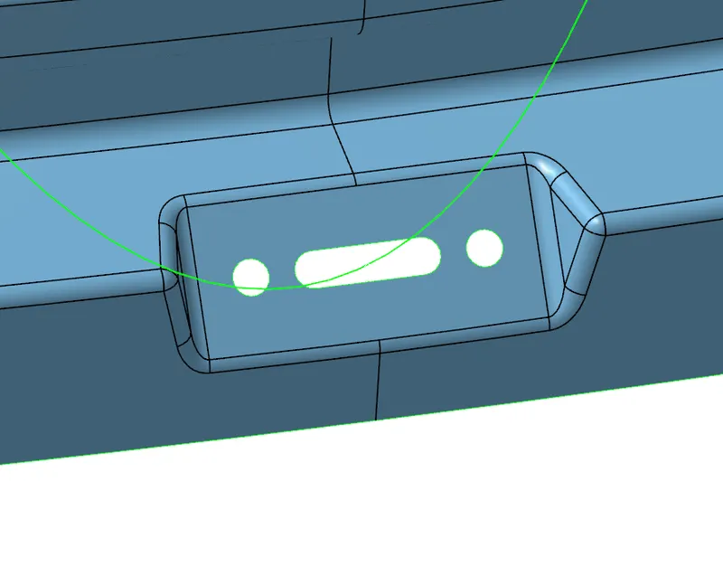
Fig 30: Created sticker provision.
15. Now thicken the created surface inner panel surface with the thickness value of 0.75mm.
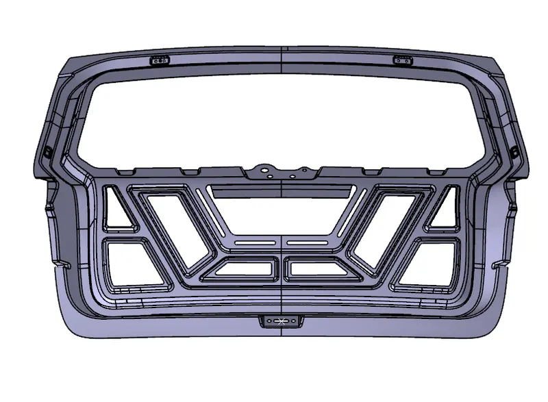
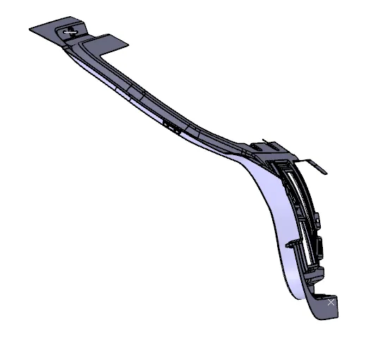
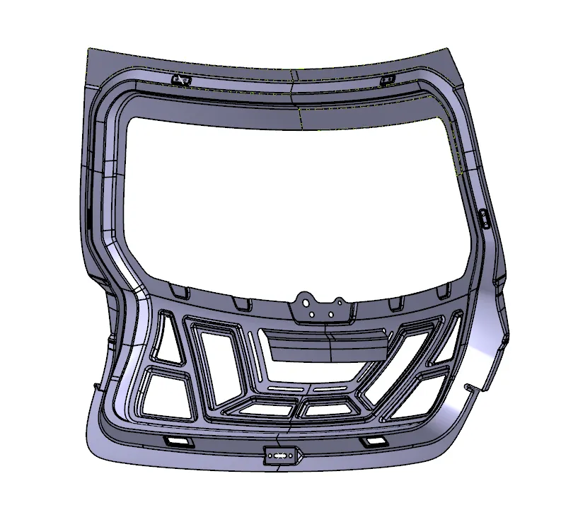
Fig 31, 32 & 33: Inner panel solid structure created from the styling surface.
16. Now a draft analysis is to be performed for the created solid panel. Draft analysis is a tool in CAD software that helps the user to see whether the part designed by them can be removed from the tool being used to make it. In the case of plastic injection moulded parts it also allows the designer to see if there is enough draft on the part to ensure that it can be correctly grained. A user can confirm that the designed part is suitable for production if the colour green is hilited from the top view, blue colour on the sides and red on the bottom side of the component. Usually, the draft angle for plastic components is given up to 3 degrees whereas for the sheet metal components the draft angle is given up to 7degrees.
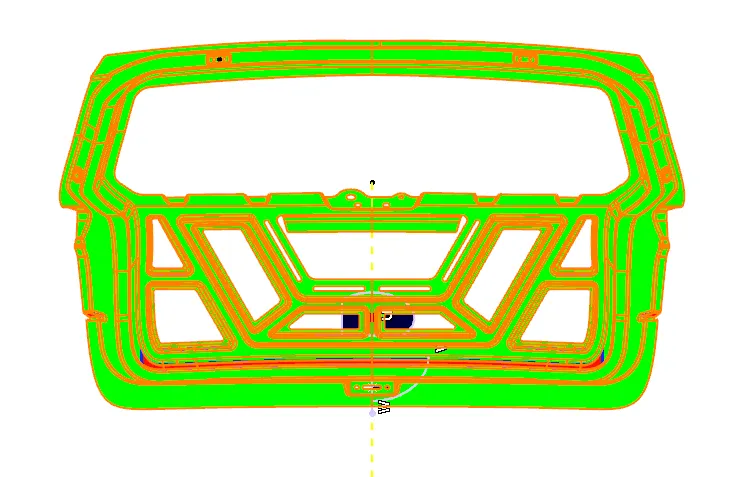
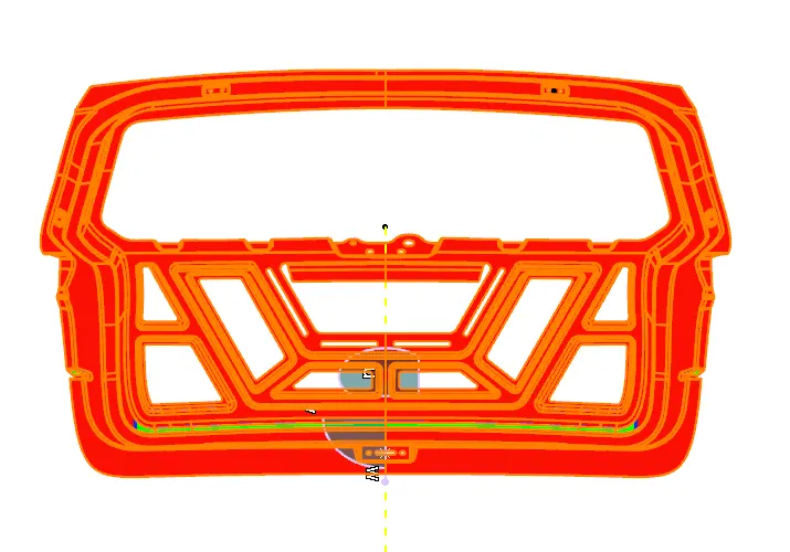
Fig 34 & 35: Draft analysis for the inner panel.
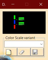
Fig 36: Draft analysis value.
Few regions such as near the hinge and gas stay embossments the colour may be highlighted in red. This means the provisions for these embossments may require another step for manufacturing after the main manufacturers of the total component.
(iii) Reinforcements:
1. Now the reinforcements are to be created for the hinge, gas stay, viper motor and the striker embossments. Reinforcements are the extra pieces of sheet metals with thicknesses of up to 1.25mm which are placed where a component will be attached to another component. This provides protection for the main component by avoiding the wear and tear of the sheet metal during long-term usage.
2. To create the reinforcements, first, extract the embossment and nearby surfaces from the inner panel and cut the extracted surface to a required shape and length.
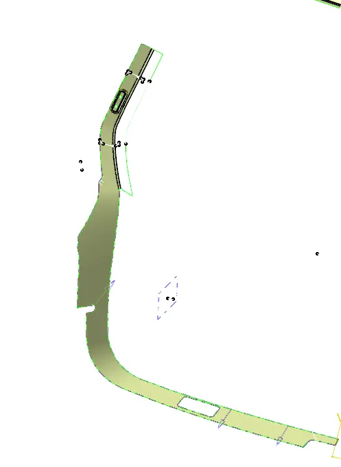
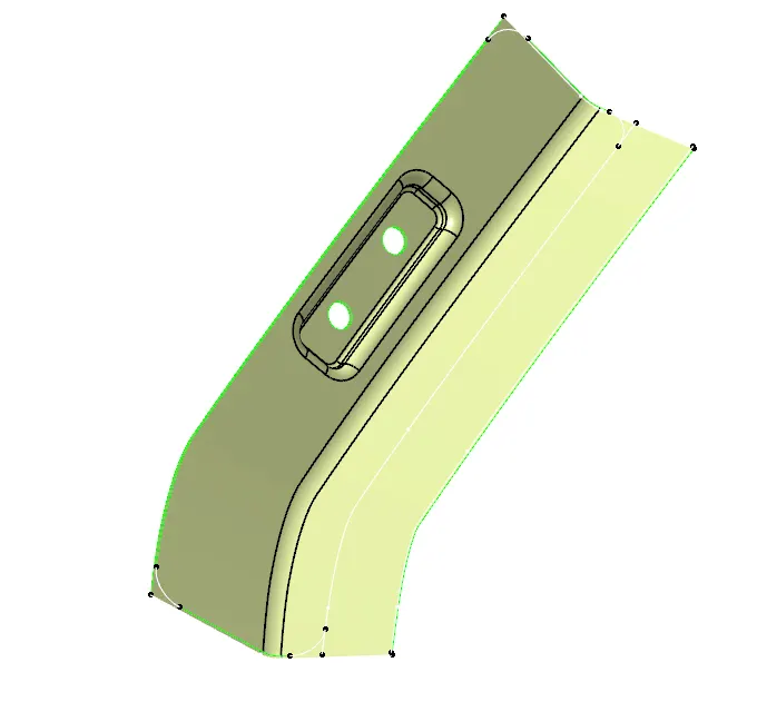
Fig 37: Extracted surface. Fig 38: Surface created for the reinforcement.
3. Offset the above surface to the value of 0.2 and the value of the inner panel thickness. Now thicken the offset value for up to 1.25mm.
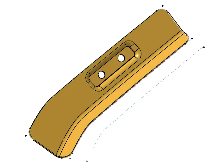
Fig 39: Created solid sheet metal reinforcement.
4. Now the created reinforcement is for the left gas stay embossment. The reinforcement for the right side can be created using the symmetry option.
5. Similarly create the embossments for the remaining regions as shown below.
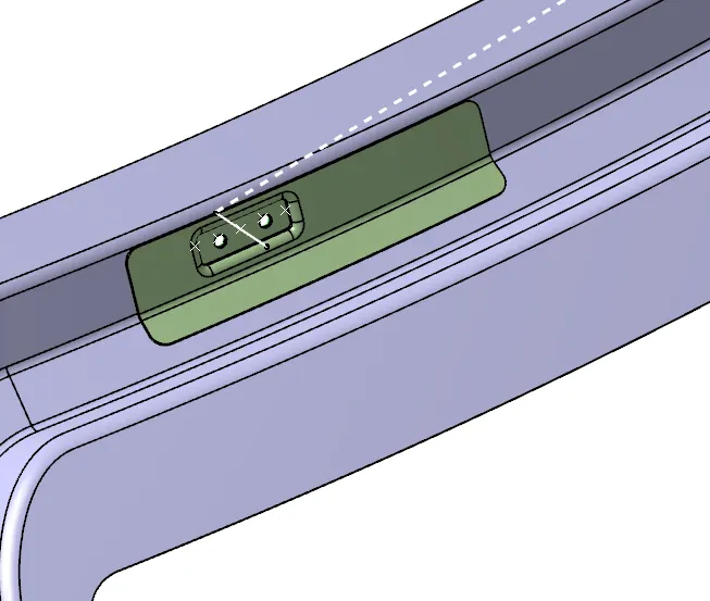
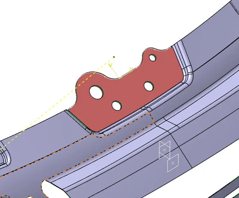
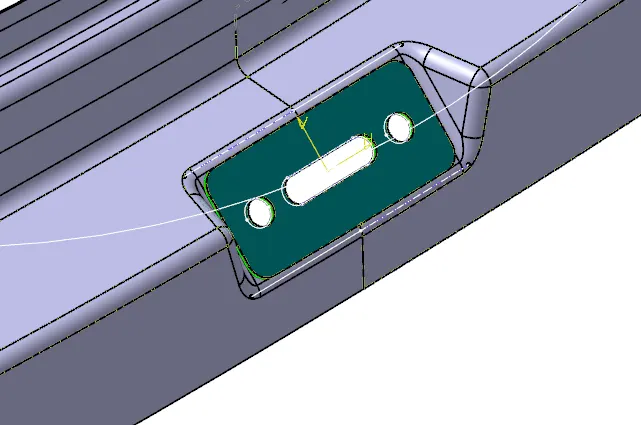
Fig 40: Left hinge reinforcement. Fig 41: Viper motor reinforcement. Fig 42: Stricker renforcement.
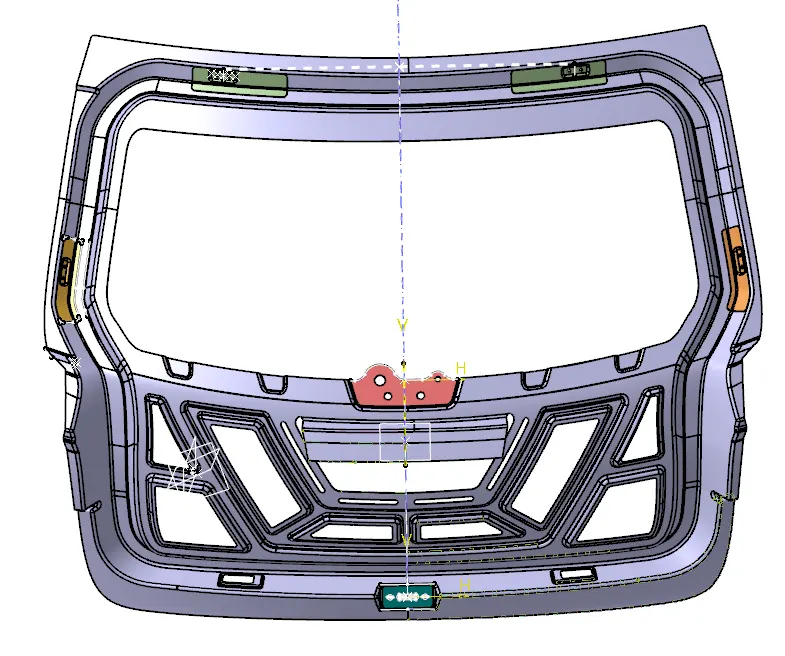
Fig 43: Reinforcements provided on the inner panel.
After creating the reinforcement assemble all the created component in the assembly workbench.
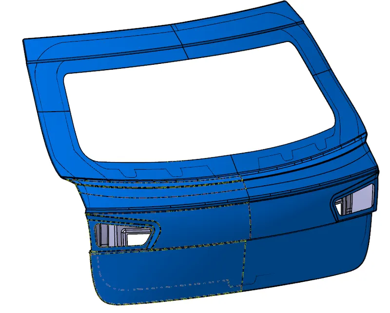
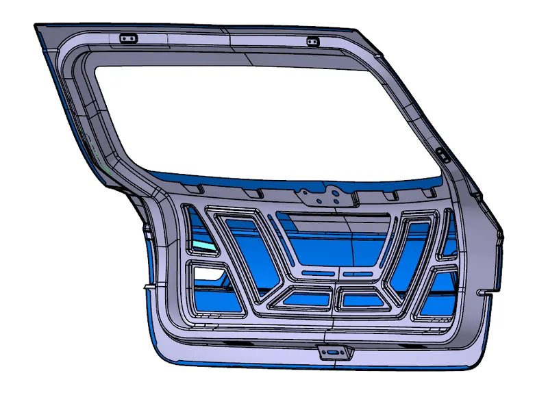
Fig 44: Back door assembled Fig 45: Back door assembled from the inner side.
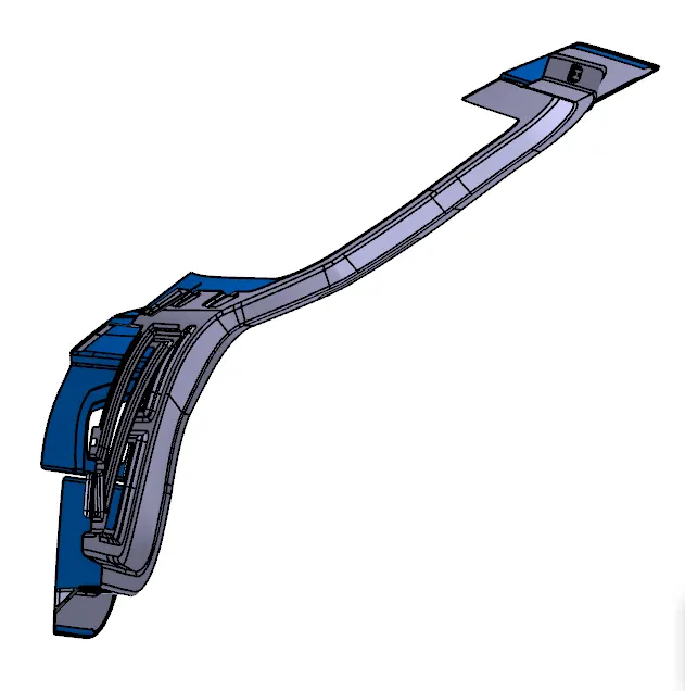
Fig 46: Back door assembly sectional view
Result:
Thus creating the back door components from the given styling surface and the draft analysis for the inner panel is completed.
Back Door model Link: