Design of backdoor
Challenge: Design the Back door of the car using the given Class-A Surface, also create the Back door inner panel & reinforcements for the hinge, gas stay, wiper motor & striker.
Back Door/Tailgate
A tailgate is a door at the back of a truck or car, which is hinged at the bottom so that it opens downwards.
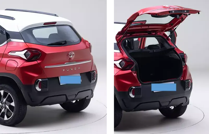
Fig 1: Back Door/Tailgate
The back door provides access to the luggage compartment. In most cars, these back doors are operated with the help of gas, reducing the effort required to lift the door. Some luxury cars have a powered backdoor which in turn is driven by an electric motor.
Types of the back door/tailgate
Top-Mounted:
This type of back door is used in station wagons, pickup trucks, and some sport utility vehicles. Today’s modern cars use top-mounted tailgating systems which are both powered and also gas stay supported. These top-mounted tailgates provide greater rear visibility compared to side-mounted or bar doors which have canter pillars in them.
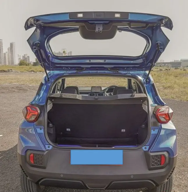
Fig 2: Back Door/Tailgate (Top-mounted)
Side Mounted Doors:
As the name signifies side-mounted doors are the one which is used in the van type MPVs, SUVs, pickup truck vehicles. These side-mounted doors or barn doors are a lot easier compared to top-mounted doors. These doors are generally smaller in size and can be easily accessed.
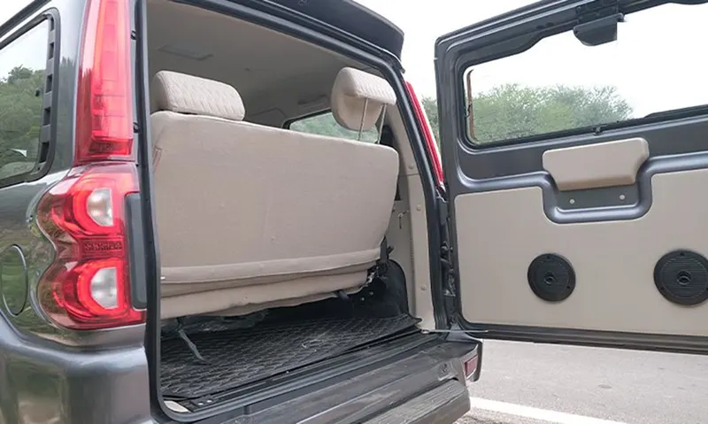
Fig 3: Back Door/Tailgate (Side-mounted)
Types of mechanisms used to open & close the Back Door:
Gas stays:
Gas stay types backdoor /tailgate is an ideal and most commonly used tailgate mechanism from lower segment car to luxury car segment. The ideal components of the tailgate consist of a hinge, door, gas stay, and some rubber beadings for the sealing of the door.
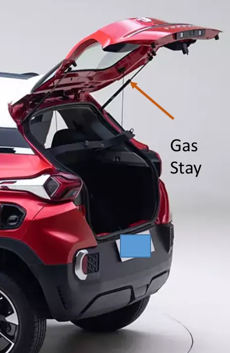
Fig 4: Gas stay position on a Back Door/Tailgate
Powered lift system:
The power trunk lid system is another sophisticated way of backdoor /tailgate opening mechanism which is to automatically open and close the backdoor /tailgate and release the latch by the touch of a button.

Fig 5: Powered lift Back Door/Tailgate
Design Considerations in Back Door Design:
The following are the Design considerations taken while designing the Back Door. They are,
- Material Selection
- Force Dissipation
- Latch trajectory
- Hinge Position
- Gas Stay Position
- Joining/assembly process
All these design considerations go hand in hand with each other because these positions are dependent on each other and if the position gets altered all the positions have to be altered for effective opening and closing of the back door. The Latch and Striker, Hinge Position and Gas Stay Positions have to be maintained properly so that they play a major role in the opening and closing as well as the rear Visibility criteria of the car.
Material Selection:
The material selection plays a major role in determining the overall weight of the back door. The materials generally used are Steel and Aluminium. The Density of Steel is higher than Aluminium thus it results in adding more weight to the door. The material is used based on the budget of the car, because the cost of steel is very cheap than Aluminium. If aluminium is used instead of steel there is no need for many parts like Reinforcements for each mounting and the overall weight gets reduced by 6-10 kg approximately. But the drawback is Aluminium is much costlier than Steel. Hence based on the budget of the car aluminium is used. In higher-end models like Benz, Audi, Porshe and BMW we can find aluminium is used instead of steel resulting in reduced weight and increased performance of the vehicle.
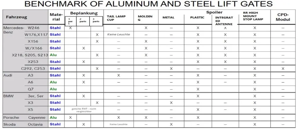
Table 1: Materials used to make Back Doors
Another factor to make a note of is using Casted Aluminium instead of deep drawn Steel components and adding reinforcements to it the space of the luggage commodity gets increased by a certain amount because the draft angle for Casted aluminium is much lesser (3 degrees) than the deep drawn Steel inner panel (7-9 degree). Thus it reduces the space between the inner and outer panel resulting in much larger cabin space than the deep-drawn steel inner panel. Thus the material selection is one of the design considerations taken. Since it reduces the space between the inner and the outer panel the rear visibility of the car is also improved giving more space for the mirror to view.
Hence in this design the material chosen is steel since it is designed for a medium-budget car and hence high cost could not be afforded to design the back door.
Force Dissipation:
The major criterion in designing the back door or any BIW part is the force dissipation during an impact or a collision. Hence studies are being done to dissipate the force on the sides and avoid it reach the inner cabin of the car so that possible damage of impact inside the car is reduced. Hence to do that the V or Y embosses are created on the inner panel so that the force gets transmitted onto the sides instead of reaching it on the cabin. This is one of the main criteria in back door design.
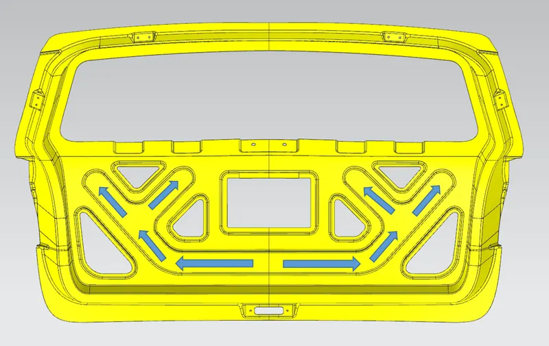
Fig 6: Force Dissipation in Back Door/Tailgate
Thus from the above image, it is clear that the forces are dissipated on the sides instead of reaching inside. This is the reason to have Y or V embosses on the panel to increase the stiffness and dissipate forces onto the sides.
Latch Trajectory
Latch trajectory is the path in which, Hood rotates during the opening & closing of the hood. A centre line is created along the hinge axis line, the midpoint of this axis line is the actual centre of the trajectory. A line is drawn at the centre of the striker. The distance between the trajectory centre & the tip of the striker is the Radius of the trajectory. It is a very important aspect in hood design, to decide on the hinge, latch, and striker installation points.
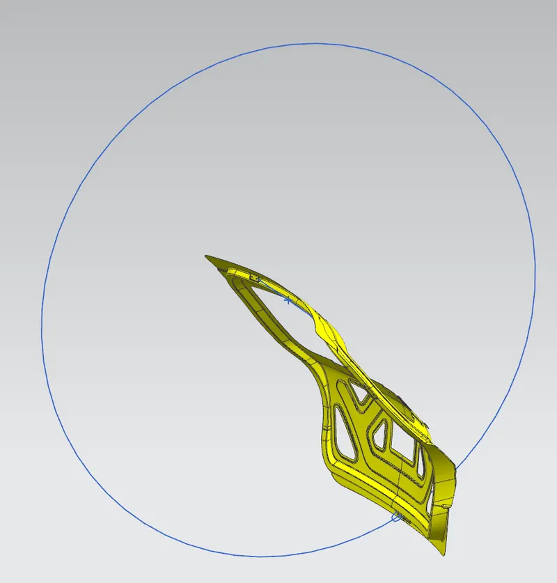
Fig 7: Latch Trajectory of Back Door/Tailgate
Sheetmetal Operations in Car back door inner panel manufacturing
Deep Drawing
The deep drawing process is a forming process that occurs under a combination of tensile and compressive conditions. A flat sheet metal blank is formed into a hollow body open on one side or a hollow body is formed into a hollow body with a smaller cross-section.
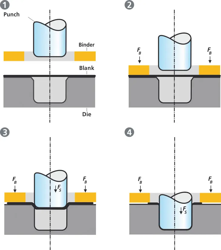
Fig 8: Sheetmetal Deep Drawing
Hemming
Hemming is a forming operation in which the edges of the sheet are folded or folded over another part to achieve a tight fit. Normally hemming operations are used to connect parts, improve the appearance of a part, and reinforce part edges.
In car part production, hemming is used in assembly as a secondary operation after deep drawing, trimming, and flanging operations to join two sheet metal parts (outer and inner) together. Typical parts for this type of assembly are hoods, doors, trunk lids, and fenders.
The accuracy of the hemming operation is very important since it affects the appearance of the surface and surface quality. Material deformations, which occur during the hemming process, can lead to dimensional variations and other defects in parts. Typical hemming defects are splits or wrinkles in the flange, material overlaps in the corner areas, or material roll-in. This is why it is important to provide the required relief at the corners.
There are two types of hemming operations,
Conventional die hemming
In conventional die hemming, the flange is folded over the entire length with a hemming tool.
Fig 9: Open Hemming
Roll hemming
It is the roll hemming process that is used for automotive sheet metals. Roll hemming is carried out incrementally with a hemming roller. An industrial robot guides the hemming roller and forms the flange. Roll hemming operation can also be divided into several pre-hemming and final hemming process steps. Roll hemming is very flexible to use and tool costs are significantly lower as compared to those of conventional die hemming. However, the cycle times are much higher since the hemming is realized using a hemming roller that follows a defined path.
Fig 10: Roller Open Hemming
Emboss definitions
Sheet metal embossing is a stamping process for producing raised or sunken designs or reliefs in sheet metal. This process can be made using matched male and female roller dies, or by passing a sheet or a strip of metal between rolls of the desired pattern.
Fig 11: Embossing Process
Automotive Sheet Metal Parts joining techniques
Mastic Sealant:
Mastic sealant works as an adhesive between the parts & also provides sealing. Generally, it is used to fill the gaps between the parts. This method of joining is adapted to avoid burn marks created during welding and also to avoid the aesthetic appearance of the panels. The mastic sealant between the inner and outer panels of the hood will get hardened inside the furnace. Every mastic sealant point will tend to improve the local strength to around 80 mm in diameter. Considering this, the mastic points are positioned such that most of the hood region is covered.
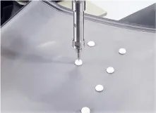
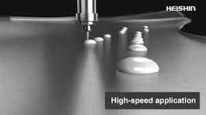
Fig 12: Mastic sealant
Spot welding
Spot welding (also known as resistance spot welding) is a resistance welding process. This welding process is used primarily for welding two or more metal sheets together by applying pressure and heat from an electric current to the weld area.
It works by contacting copper alloy electrodes to the sheet surfaces, whereby pressure and electric current are applied and heat is generated by the passage of current through resistive materials such as low-carbon steels.
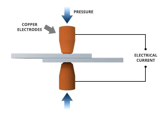
Fig 13: Spot welding
Creating Back door assembly components using NX
Input
- Material thickness
- 0.75mm for the Outer panel upper & lower, the inner panel
- 1.5mm for all reinforcements
- Class-A surface
Procedure
Back door outer panel upper
Given Class-A surface examined for gaps & irregular surfaces. Improvisation is done to get a single upper surface.
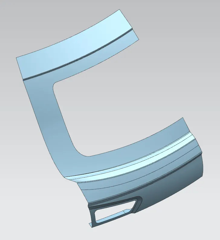
Fig 14: Back door outer panel upper Class-A
The upper panel of the back door holds the inner panel with the help of open flanges created in its design. To create an open hem with a 10mm length, the panel is offset by 2.65mm, this gap is enough to hold the inner panel which is 0.75mm thick.
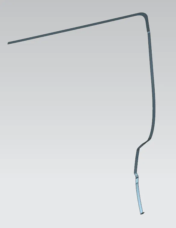
Fig 15: Flange
A surface is created perpendicular to the panel surface using the law extension, and then using the 3-face blend option open flange is created.
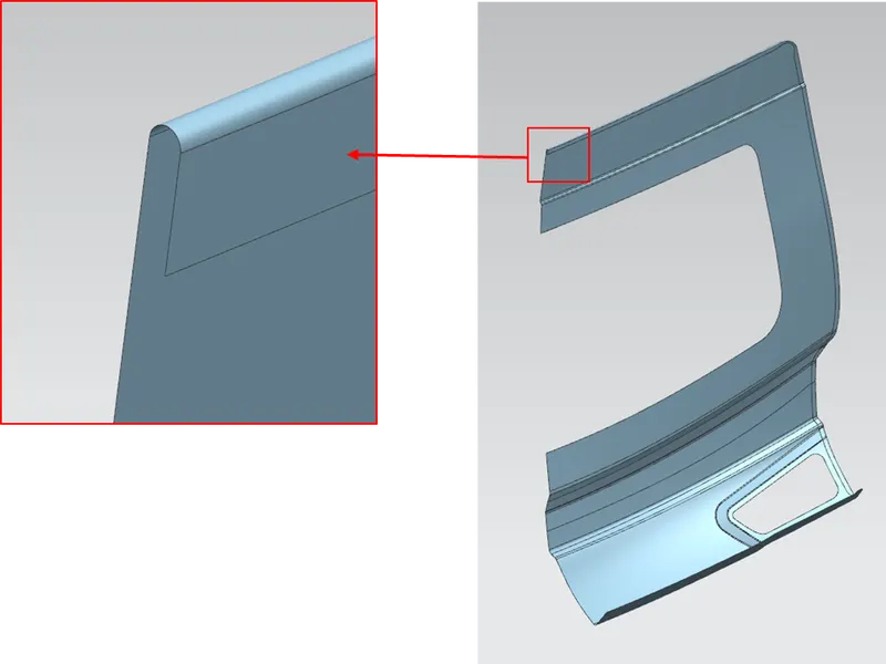
Fig 16: Open hem
The first half of the panel is created, mirrored & joined together. A thickness of 0.75mm was applied to the surface.
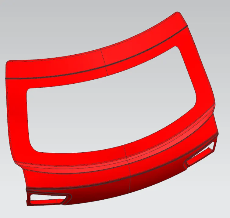
Fig 17: Back door outer panel upper
Reliefs are made to decrease the stress concentration along the corners and also to decrease the clumping of metal along the corners, this is done by trimming the corner by a minimum radius for the rollers to pass along smoothly.
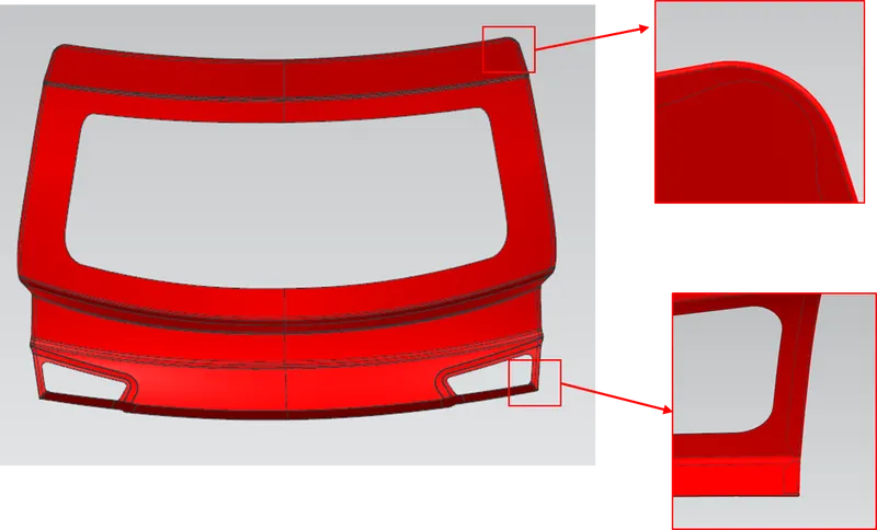
Fig 18: Upper panel Reliefs
Back door outer panel lower
Given Class-A surface examined for gaps & irregular surfaces. Improvisation is done to get a single lower surface. Flange is created using by taking the upper panel flange as a reference
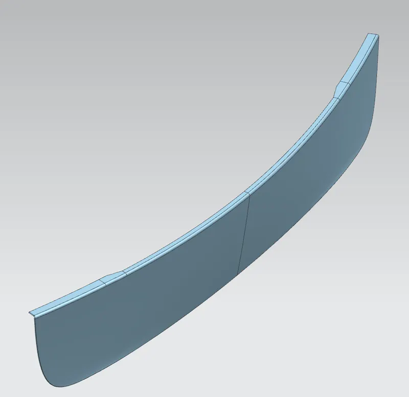
Fig 19: Back door outer panel lower
Whatever procedure followed to create the upper panel, the same followed to create the lower panel.
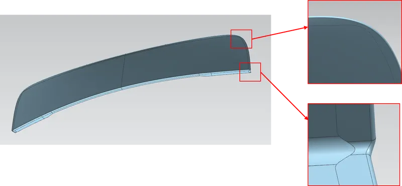
Fig 20: Lower panel reliefs
The first half of the panel is created, mirrored & joined together. A thickness of 0.75mm was applied to the surface.
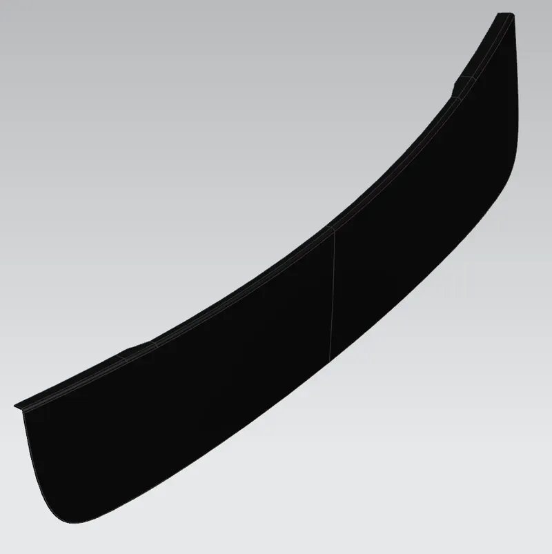
Fig 21: Back door outer panel lower
Back door's inner panel
A sealing flange is created by offsetting the surface to a distance of 1.7mm, which will give the inner panel surface position.
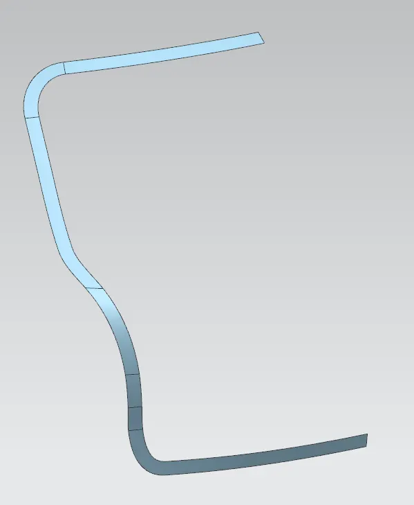
Fig 22: Inner panel sealing flange
In between, the tangent tensioning (Shape control) can be adjusted by modifying the surface using the Bridge curve tool. This flange has to be in a depth of 30 mm from the surface. Now connect the flange with the surface using law extension w.r.t the tooling axis and the proper draft is given.
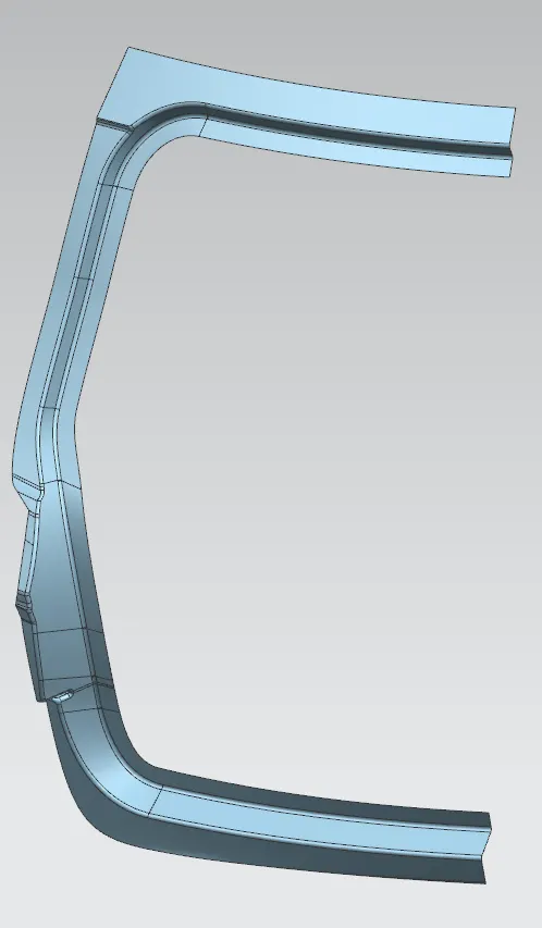
Fig 23: Inner panel connecting flange-1
A surface was created around & below the rear windshield area by taking the reference of the back door outer panel upper & lower surfaces.
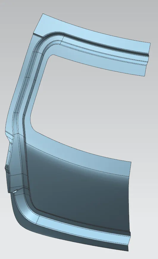
Fig 24: Inner panel rear windshield area
Cut out made below the rear windshield area to create the flange which is attached to the back door outer panel upper using mastic sealant.
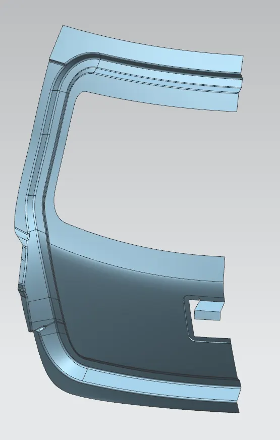
Fig 25: Inner panel connecting flange-2
Embosses are created at various places to provide access to assemble hinges, gas stay, wiper motor & striker. Embosses & cutouts are created below the rear windshield area to reduce panel weight & also improve its structural strength.
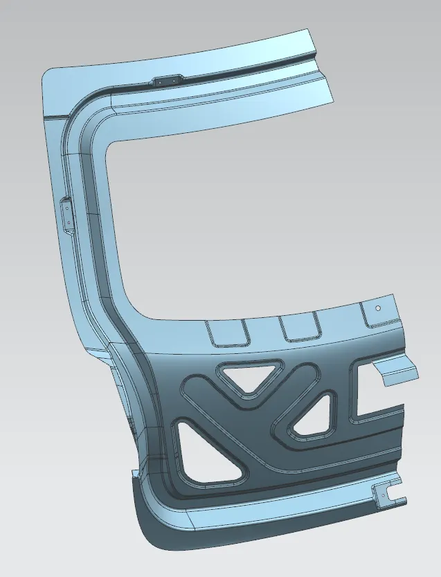
Fig 26: Inner panel embosses
The first half of the panel is created, mirrored & joined together. A thickness of 0.75mm was applied to the surface.
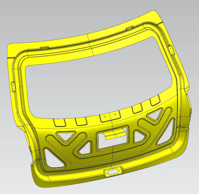
Fig 27: Back door inner panel
Reinforcements:
Reinforcements are generally used to increase the strength of the mountings so that there are no unnecessary dents or noise occurs at the time of motion. This not only adds strength to the part but also increases the overall stiffness of the part so that the part is completely stable. The Reinforcements used are
- Latch and Striker Reinforcement
- Wiper Motor Reinforcement
- Hinge Reinforcement
- Gas Stay Reinforcements
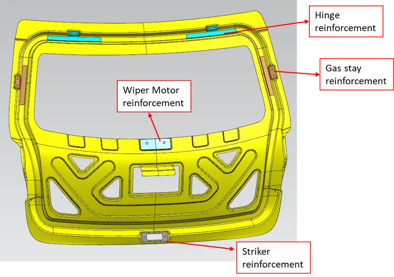
Fig 28: Reinforcements
Assembly
All the parts were called into the assembly environment, Parts were assembled at the proper positions & fixed so that the DOF of all the parts are zero.
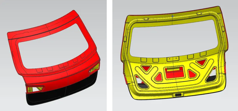
Fig 29: Back door assembly
Gaps were maintained as per general guidelines.
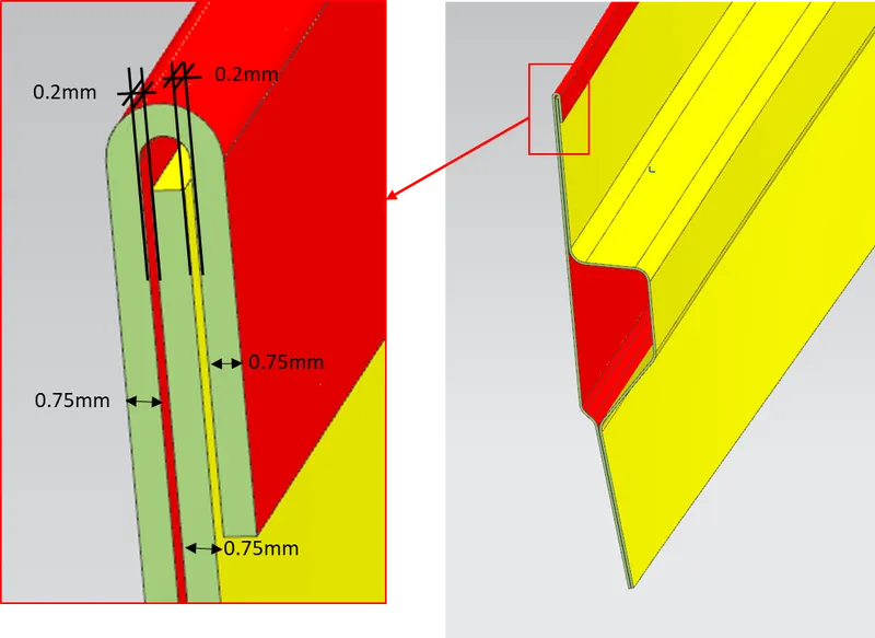
Fig 30: Gaps between the parts-1
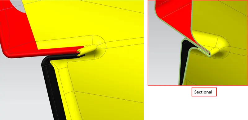
Fig 31: Gaps between the parts-2
Draft Analysis
A sketch is made on the XY plane as shown in the below figure to create the Tooling Axis.
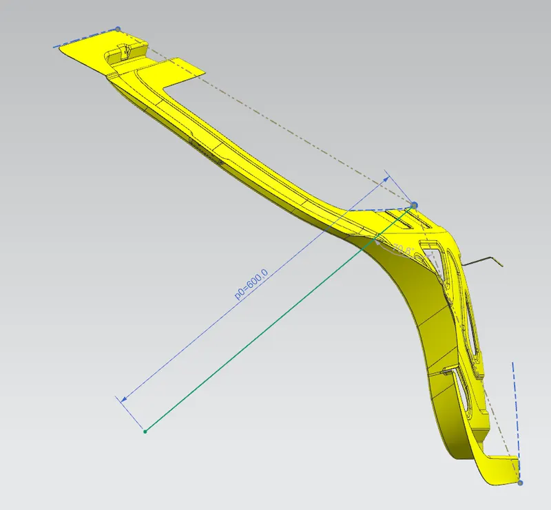
Fig 32: Tooling Axis
Draft analysis performed along the tooling axis created.

Fig 33: Draft analysis of the back door inner panel
Conclusion:
Back door Assembly & its parts were created by following all design guidelines.