Design of backdoor
Aim:
To design Back Door by using the styling surface provided and by using the appropriate design methodologies to make the necessary reinforcements and emboss.
Intoduction:
Backdoor:
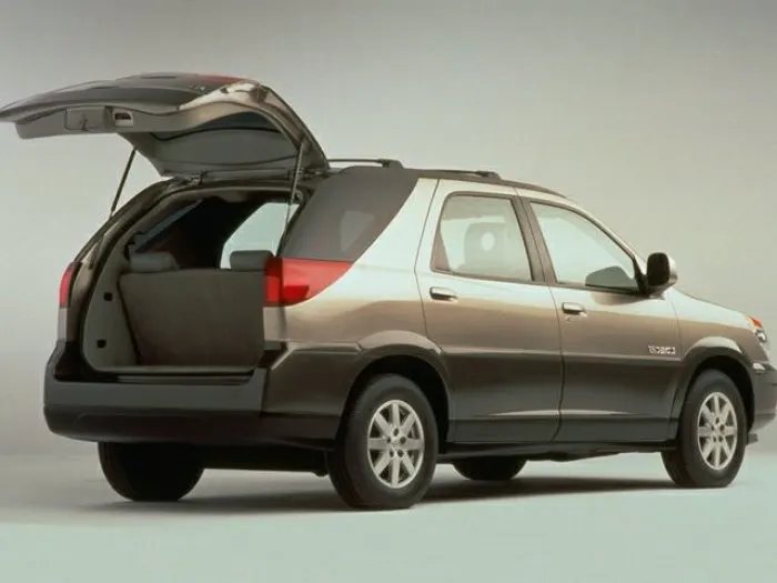
- Backdoor is the part of a vehicle which is mounted on the rear side of a car. It helps in covering the luggage area with the help of sealant which keeps inside of the vehicle air tight and prevents water to enter into the car. The back door, sometimes referred to as the "Hatch," "Tailgate," "Trunk-lid," or "Boot-door," is a four-door car's fifth door.
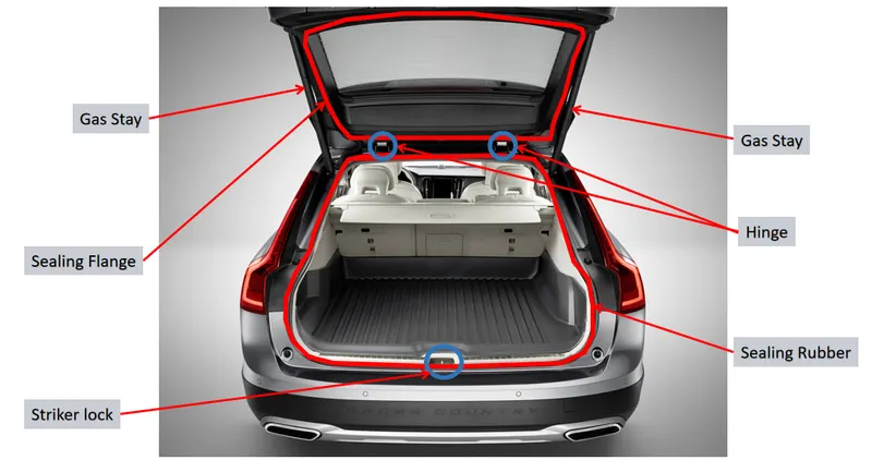
- It's the region behind the last passenger seats generally. It has striker mounting as well as wiper motor mounts, tail lamps, and hinges to support the weight of the trunk when it is open, gas stays to help open and close the trunk, radars, cameras, and other features.
- A Door is a hinged part which is used for entry and exit of the vehicles. Backdoor are one of the type of door of the vehicle which are located next to the passenger seat which provides access to the luggage compartment. In the most of the cars, these back door are operated with the help of gas stay which in turn reduces the effort required to lift the door. Some luxury cars have powered backdoor which in turn is driven by an electric motor.
- This kind of system is also called a powered trunk lid system hatchback or station wagons are sold as 3 doors or 5 doors models. In this case, the rear hatch is classified as door this is because it enters the passenger compartment. The naming is mainly used in Europe countries. In case of safety, the backdoor designed should meet the safety requirement of the rear collision.
Types of the back door:
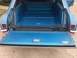
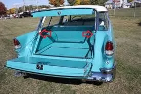
The door or opening of a cargo area may be hinged at the top, side & bottom. If the door hinged in the bottom it is called as a tail-gate.
- Top Mounted
- Side Mounted Doors
- Bottom Type
1.Top-Mounted:
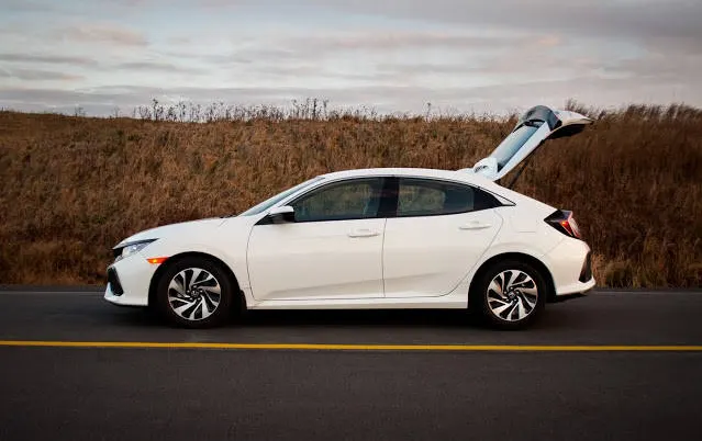
This type of back doors is used in a station wagon, pickup truck and some of the sport utility vehicles. Today’s modern cars use top-mounted tailgating systems which are both powered and also gas stay supported. These top mounted tailgates provide greater rear visibility compared to side-mounted or bar doors which have canter pillars in it.
2.Side Mounted Doors:
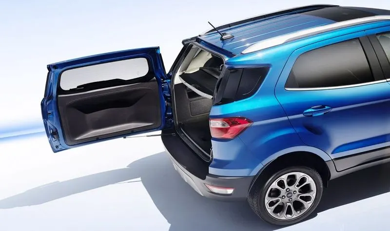
As the name signifies side-mounted doors are the one which is used in the van type MPVs, SUVs, pickup truck vehicles. These side-mounted doors or barn doors are a lot easier compared to top-mounted doors. These doors are generally smaller in size and can be easily accessed.
3.Bottom Type:
This bottom type type backdoor system are used in the car type such as car, pickup truck and some luxuary SUVs. These are the most convenient type of back door in which the bottom split is used as a support or even as a table for the tour going people.
Types of mechanisms for Back Door:
- Gas Stays Type.
- Powered Lift system.
1.Gas Stays Type:
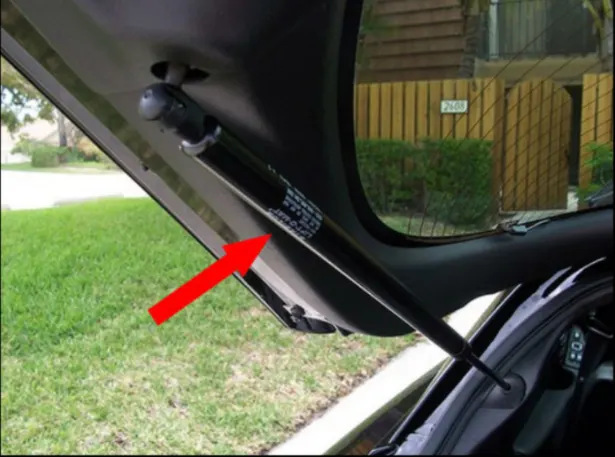
Gas stay types backdoor/liftgate/tailgate is an ideal and most commonly used tailgate mechanism from lower segment car to luxury car segment. The ideal components of tailgate consist of a hinge, door, gas stay and some rubber beadings for sealing of door.
2.Powered Lift System:
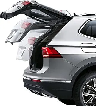
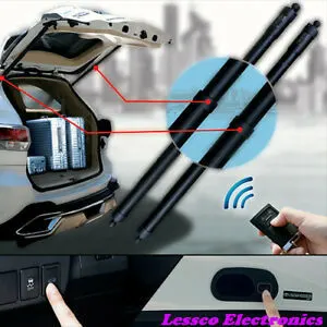
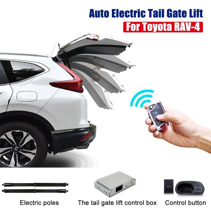
Power trunk lift system is another sophisticated way of trunk or liftgate opening mechanism which is to automatically open and close of the trunk and release of the latch by the touch of a bottom. Powered trunk Lift system consists of a power latch, anti pinch switch, PTG assly, PTG main switch. When the switch is pressed in the compartment or outside the power latch releases the latch and the entire backdoor is opened. The anti pinch switch is located in order to avoid accidental hand insertion during the operation of the door.
Manufacturing methods:
Recently, there have been two approaches to reducing automobile weight. One is by using material lighter than steel and the other is by redesigning the steel structure. Althrough the former seems very effective, it is very expensive so that it may only be used for an expensive automobile industry is trying to use steel, which is not costly and recyclable. Light weight steel can be achieved by improving the performance of the structure or adopting by improving the performance of the structure or adopting new manufacturing techniques. One of the efforts is the ULSAB (Ultra Light Steel Auto Body) concept.ULSAB suggests three main weight reduction techniques such as Hydro forming and the Tailor Welded Blank (TWB)
ULSAB (Ultra Light Steel Auto Body):
An UltraLight Steel Auto Body (ULSAB) structure was assembled, weighed and tested, validating results from the concept phase of a global steel industry study and satisfying the project goals. ULSAB has proven to be lightweight, structurally sound, safe, executable and affordable.
Tailor Welded Blank:
A Tailor Welded Blank is a blank that is compared of two seperate pieces of sheet metal that have been welded together prior to stamping. Tailor Welded Blanks allow the welding of the different grades, different thickness or different corrosion coating together in order to give the properties needed in differeent areas, without increasing the number of tools needed to form the part and eliminating the fit ability concerns. They also allow a high degree of flexibility in designing parts and large blanks can be formed from much smaller sheets. The use of Tailor Welded Blanks would reduce the weight of the car. Having the ability to selectively place different thickness of materrial would result in weight reductions. An example of this production is the door inner panel. The only strength requirement on a door inner is in the region where the hinges attach to the panel.
Design Considerations:
- Rear Visibility Criteria
- Crash requirements
- Amount of space needed
- Accessibility
- Backdoor opening style
- Mountings
- Latch and striker placement
- Wiper motor placement
- Hinge and gas stay placement
- Reinforcements
- Sealing criteria
- Clearances
- Reliefs
Design Constraints for Back Door:
The constraints for back door design are as follows:
- Rear Visibility criteria:
Federal motor vehicle safety standard (FMVSS) No. 111, “Rear Visibility,” currently requires that vehicles be equipped with rearview mirrors to provide drivers with a view of objects that are to their side or to their side and rear.The driver should be able to see from his seat to the rear side of the car. The visibility is the first and foremost factor which is taken into consideration.
- Boot Space:
The gap between inner and outer panel should be in such a way that, proper section modulus (The factor which controls the stiffness and strength of the Model ) is maintained while giving enough boot space volume inside the car.
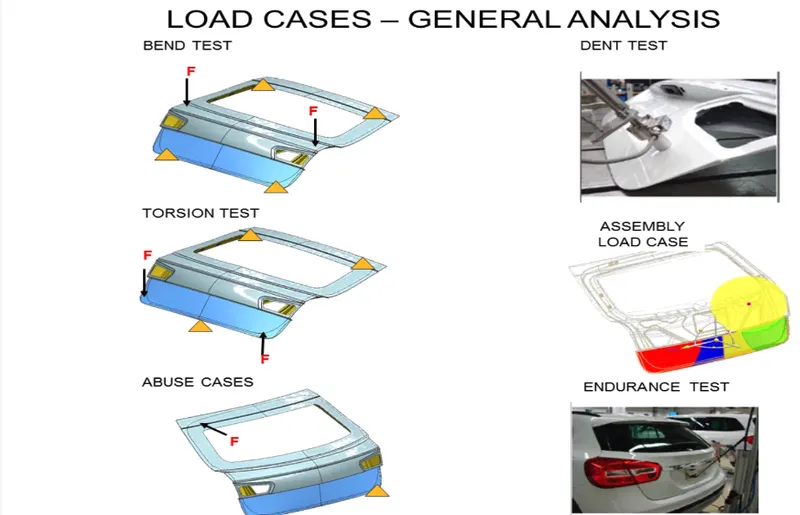
- Rear crash regulation and requirements:
- Sealing and its functions:
To make inside of the rear side of the car, sealing is provided for air and water tight for which sealing flanges are also designed. The width of the sealing flange should be atleast 25mm after blending all its edges. Sealing flanges are connected to the connecting flange to the windshield
- Joining techniques:
To join inner and outer panels the Hemming process is used and to join outer upper and lower panels Spot Welding and Laser Brazing Welding are used.
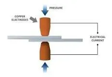
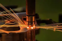
- Spot Welding:
Spot welding (or resistance spot welding) is a type of electric resistance welding used to weld various sheet metal products, through a process in which contacting metal surface points are joined by the heat obtained from resistance to electric current.
- Laser Brazing Welding:
Joining methods, in which the brazing solder is melted with the help of an industrial laser, have been used mainly in the mass production of vehicle bodies. There, laser beam brazing is mostly used for joining galvanized metal sheets or lightweight components made of aluminum, but also for other brazing material. Laser automobile brazing is usually realized with a brazing optic that is integrated in a robot. The laser beam is guided along the joint where it melts the brazing solder
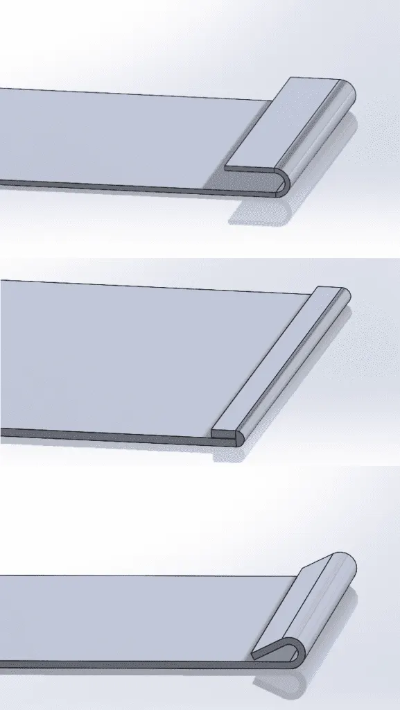
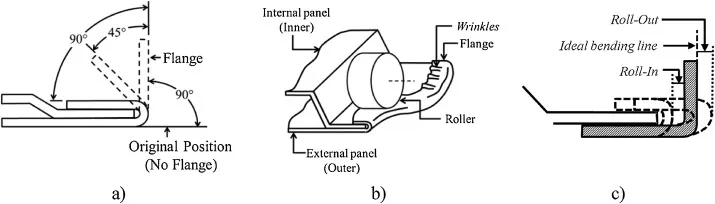
- Hemming:
Hemming is a forming operation in which the edges of the sheet are folded or folded over another part in order to achieve a tight fit. Normally hemming operations are used to connect parts together, to improve the appearance of a part, and to reinforce part edges.
Closed hems , open hems are the most common type of hems where a sheet metal is connected to another part of the sheet metal using the sheet bending process alone without using welds or rivets. So that they can give very good surface finish.
- Gap and flushness requirement:
Mastic Seals: Mastic Seals place b/w Inner and outer panel to reduce noise, vibration, and harshness. Every Mastic will have an effect of 80mm Dia. The inner and outer panel gap is 4 to 5mm. 0.2mm gap is required for the Hemming and that gap will be filled by sealed past.
- Adding reinforcements and stiffener pad:
Reinforcements are added were and all the weight is added. On the inner panel, we have Hinges and striker, which are attached to the inner panel so due to this attachment the strength of the inner panel is going weak. In order to strengthen the inner panel reinforcements will play a very important role. A stiffener pad is a sponge-like material place b/w Inner and outer panel to reduce vibrations.
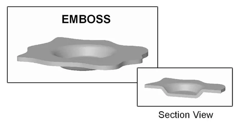
- Emboss definition:
As we design engineer need to dissipate force during any accidents by having emboss in Back Door Inner panel, An emboss is a metal forming process in which a high pressure is applied on a die to make a imprint on the working surface. In this process the metal thickness remains the same while embossing of stamping to distribute the forces produced during the impact with pedestrian or crashing by any external vehicle can harm driver and passenger. Emboss plays very important role in safety aspect both IN and OUT.
- Manufacturing Technique:
Stamping, Punching, Bending, Forming, etc. are used in back dor manufactuirng. But it also varies according to the material being used.
- Stamping:
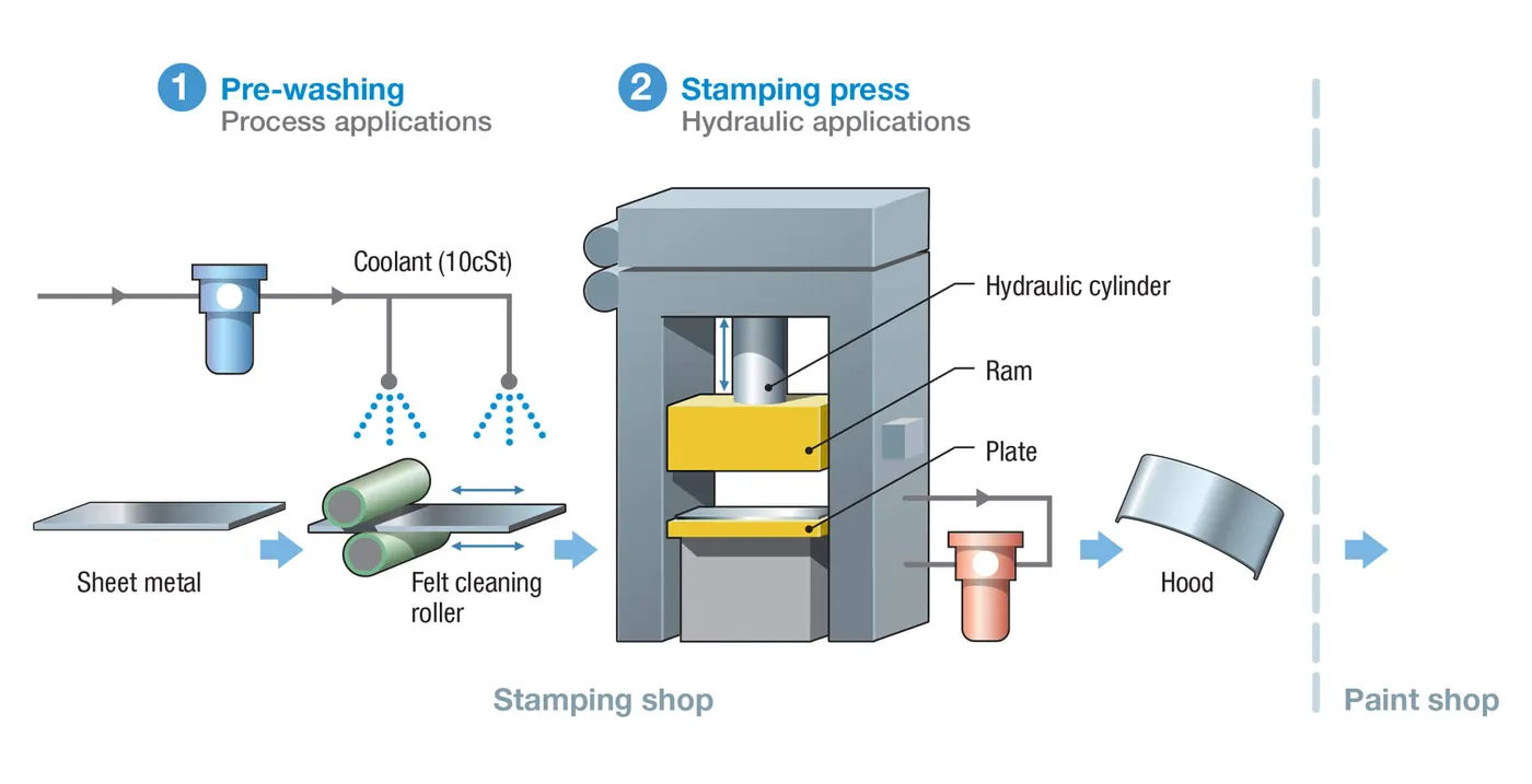
Stamping is also called as pressing which involves placing flat sheet metal, in either coil or blank form, into a stamping press. In the press, a tool and die surface form the metal into the desired shape. Punching, blanking, bending, coining, embossing, and flanging are all stamping techniques used to shape the metal.
- Punching:
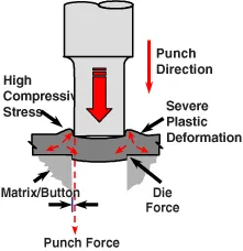
Punching is a forming process that uses a punch press to force a tool, called a punch, through the workpiece to create a hole via shearing.
- Bending:
Bending is a manufacturing process that produces a V-shape, U-shape, or channel shape along a straight axis in ductile materials, most commonly sheet metal. Commonly used equipment include box and pan brakes, brake presses, and other specialized machine presses.
- Functional Requirements of HINGE and GAS STAY / POWER LIFTER:
Hinges are provided for easy opening and closing of the back door. Gas stays are used to hold the backdoor. And for these, mountings and reinforcements are provided on the backdoor.
Parts thickness used in current design:
- Outer panel: 0.75mm
- Inner panel: 0.75mm
- Reinforcement: 1.5mm
The Different panels or regions are as follows:
1.Inner Panel.
2.Outer Upper Panel.
3.Outer Lower Panel.
Backdoor Assembly:
A backdoor is normally manufactured with 1 inner panel and 2 or 3 exterior panels that are hemmed and spot welded together as needed. Depending on the price range of the car, different materials are utilised for the backdoor. The bulk of inexpensive cars are made of steel since it is less expensive, and parts are stamped using moulds. Here, uniform thickness of the panels is maintained throughout.
However, in expensive cars, aluminium is used for the manufacturing of back door which is usually die cast. In such cases, reinforcements are not required and the vehicle is also light in weight. Varying thickness can also be achieved in case of aluminium body back doors.
1.Inner Panel
2.Outer Panel
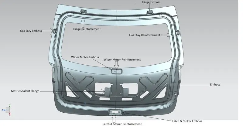
3.Hinge Reniforcement.
4.Gas Stay Reniforcement.
5.Wiper Motor Reniforcement.
6.Latch and Striker Reniforcement.
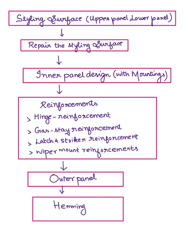
When designing the backdoor, we will divide the whole designing process into multiple steps which enables us to seamlessly create different parts of the backdoor assembly
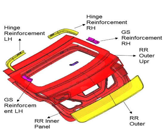
We are provided with the styling surface and we take a top bottom approach to integrate the whole assembly
1.Inner Panel:
- The inner Panel is a component which is used for strengthening the door and it is one of the most important components on which all accessories are mounted like hinges, glass guide channel, mounted trim, latch etc..,
The manufacturing method which may be used for creating the
- The inner panel includes the deep drawing process in which the whole blank is inserted into the mold and perfect drafting angle is provided to the part so that the inner panel can be ejected easily.
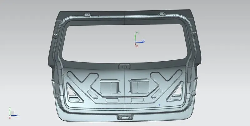
- The inner panel is designed with embosses and several mounting for the Hinge , Gas-stay, wiper motor and Latch & striker surfaces.
2.Outer Panel:
- The Outer panel of the back door is similar to other BIW components where it is the aesthetic part of a vehicle. The coating provided is of multi stage which has the property of scratch resistance, rush prevention and smooth and attractive finishes. The Outer panel also has the provisions for the tail lamp, rear fog lamp and also has the provision for lisence plate mountings. Most of the hatch back cars have the provision for wiper motor.
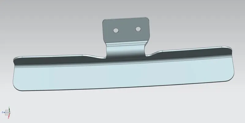
- The main purpose of reinforcements are to increase the strength of the part locally, since it is the place where the stress concentration would be great compared to other locations of the parts
3.Hinge Reinforcement:
- Hinges support the complete weight of the whole backdoor. Hence a hinfe mount reinforcement are provided here too. Embosses is designed such that the hinges should operated freely. The electrical wiring looms are through the holes along the periphery to keep them hidden.So the hinge reinforcements are made with sufficient strength to carry the loads
4.Gas stay Reinforcement:
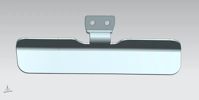
- An angled or Diabolic emboss is provided for the gas stay mounts. The angle makes it easy to be machined and stamped. It is reniforcement with a thicker sheet.
5.Wiper motor Reinforcement:
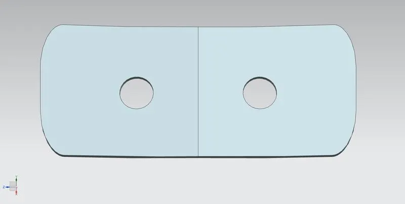
- A dedicated space near the window is left for wiper motor assembly. A cavity is placed preferably in the middle of the panel to accommodate all the necessary wiper motor components.
- The holes or cavities are placed strategically to accommodate wiring looms, tail lamp mount, and other accessories. Embosses help stiffening the panel and act like local reinforcements. Extensions are provided around holes which are attached to outer panels and acts are crumple zone elements in case of rear impacts.
6.Latch and striker Reinforcement:
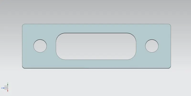
- At the bottom of the latch and striker assembly. Generally a key operated or automatic remotely controllable locking mechanism is used to keep the door closed and open.
- Another purpose of the emboss design is to distribute impact force towards hinges and latch assembly which are reinforced and can absorb them.
PROCEDURE:
1.Checking the Geometry:
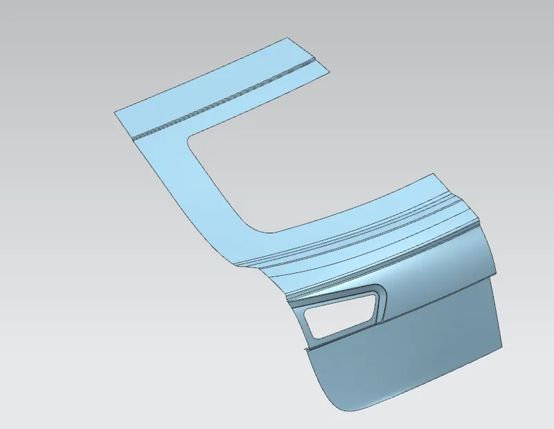
- Once the model is opened, we get a Class A Surface of the back door. The image is shown below
- Try joining the Styling surface of the car, if the surface sews together, we get the outer surface.
- If the surface didn’t join then we need to create the surface by using Offset Curve in Face command which is used to offset curve in the selected face.
- Then trim the the surface using the offseted curve using Trim Sheet comand.
- Then the the curve is created between trimed surface using Bridge Curve command.
- Then using Through Curve Mesh or Studio Surface command create the surface based the bridge curves.
- Now the surface is created then the sew command is used to join the Styling surfce.
- Then join the all the Stylling surfaces using Sew command, if any sew throws error repeat the above mentioned process.
- These fillet areas, Tail Lamp areas as those areas will be vulnerable and are unable to join together. So we created these areas by using above procedures.
- It is Top Down Assembly Approach, So we fix this panl and by using Wave Geomentry Linker command we design Inner panel, Outter Upper and Lower Panel and Reinforcements.
2.Tooling axis creation:
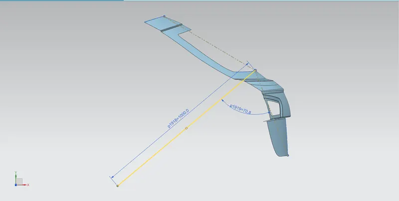
- Create a sketch using Sketch command.
- Then a line from left and right extremities almost parallel to the path of the surface along the unsymmetrical axis using line command.
- Then create a bsecting line by using the Derived Lines command.
- This line represents the Tooling Direction .The image is shown below:
3.Creating Inner panel:
- First offset the surface to a distance of 1.7mm using Ofsect Surface command, which will give the inner panel surface position.
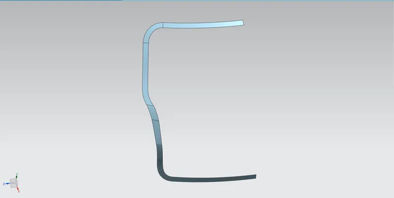
- Then the Sealing Flange for the inner panel has to be created.
- The Seaing Flange created by offseting the curve by using Offset Curve in Face.
- Then the Sheet is trimed with the offseted curve using Trim Sheet command.
- Then if any gap is created then the curve is brdige created by using Bridge Curve command.
- The tangent tensioning (Shape control) can be adjusted by modifying the bridge curve using the Bridge curve command.
- Then using Through Curve Mesh or Studio Surface command create the surface based the bridge curves.
- Following these procedures the Sealing Flange is created. The image is shown below:
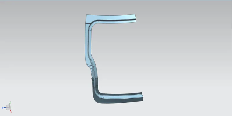
- Then Connecting Flange is created by connecting the Sealing Flange with the Surfce by using Law Extension command with respect to the tooling axis and also providing proper draft angle.
- Then Fillet is applied by using Face Blend command.
- Then the Upper Surface and Lower surface is joined by Creating the Bridge Curve using Bridge Curve commnad.
- Then the surface is created by using Swept command woth respect to the bridge curve.
- Then the created surface is trimmed with the Upper and Lower surface using Trim and Extend command. The Connecting Flange image is shown below
- Check whether the surface is getting thickened or not on every flange creation.
- Then the Windshield surface is to be created.
- First we create the Upper Windshield surface by extracting the upper windshield surface using Extract Surface command.
- Then the similar steps of Connecting Flange are followed to create Upper Windshield surface. The Upper Windshield Surface image is shown below
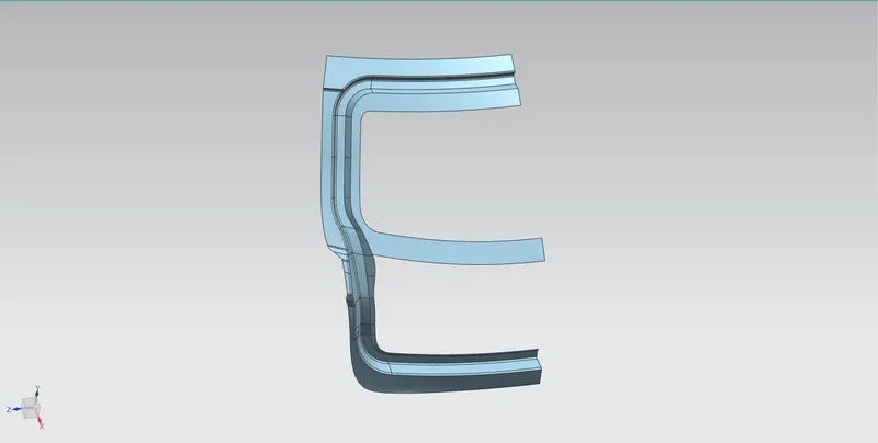
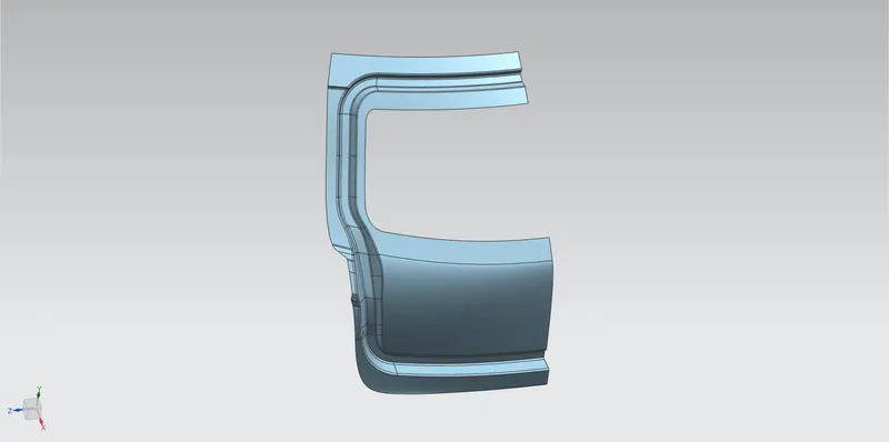
- Then The lower Windshield surface by creating bridge curve between the upper windshield surface and connecting flange uisng Bridge Curve command.
- Then using Studio Surface with respect to the bridge curve the surface is created.
- Then the Blend is applied using Face Blend command. The Windshield Surface image is shown below
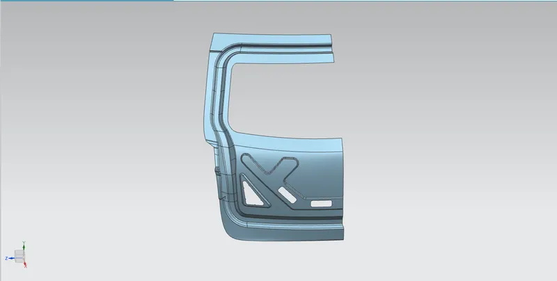
- Then the emboss is created by creating the sketch using Sketch command.
- Then the sketch is embossed using Emboss command . The Emboss image is shown below
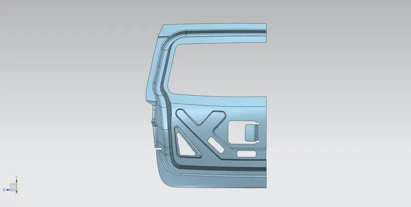
- The Mastic Sealant Flange is created where the mastic will be placed which is used for joinning process. The Mastic Sealant Flange is shown below
- The Hinge emboss is created by creating the Sketch using Sketch commnad.The sketch image is shown below
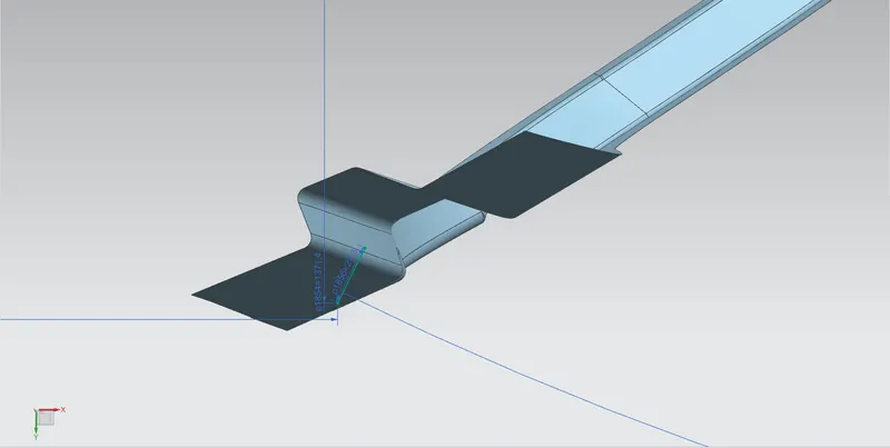
- Then the sketch is extruded using Law Extension command.
- Then the surface edge is extruded using Law extension command.
- Then the created surface is trimed with inner panel using Trim and Extend command.
- Then the blends are applied using Edge Blend commnad. The Hinge Emboss image is shown below
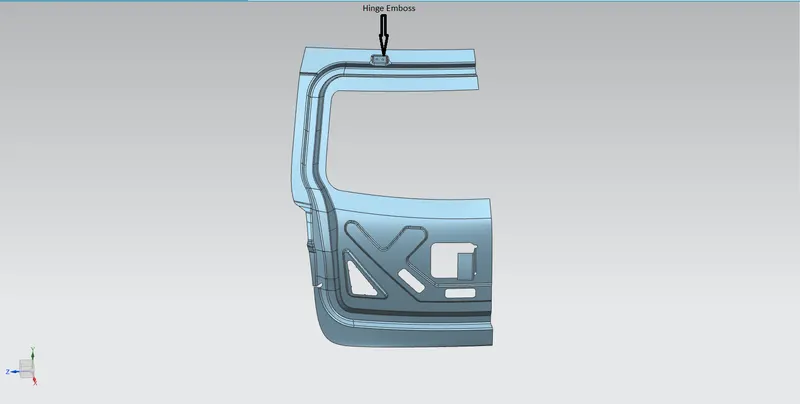
- The same procedure of creating Hinge Emboss is used for creating the Gas Stay Emboss. The Gas Stay Emboss image is shown below
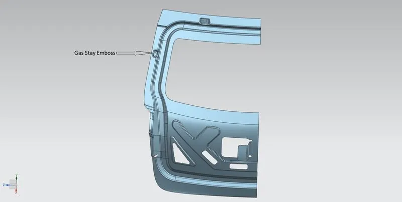
- The same procedure of creating Hinge Emboss is used to create the Wiper Motor Emboss. The Wiper Motor Emboss image is shown below
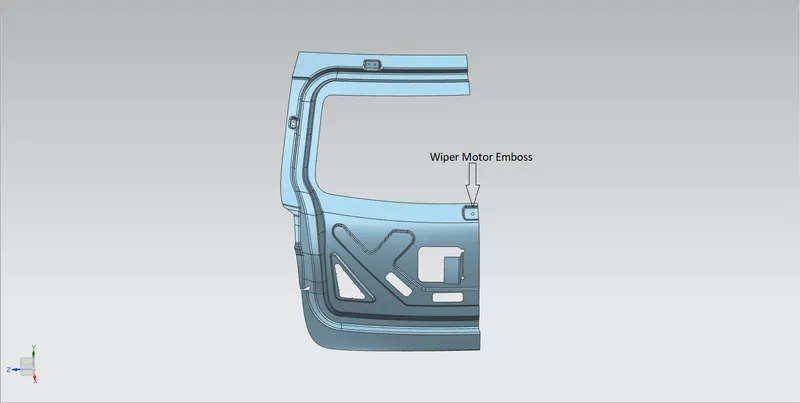
- Then the Inner panel is mirrored using Mirror command.
- Then we create trajectory for opening/closing with respect to the hinge axis.The Trajectory for opening/closing with respect to the hinge axis is shown below
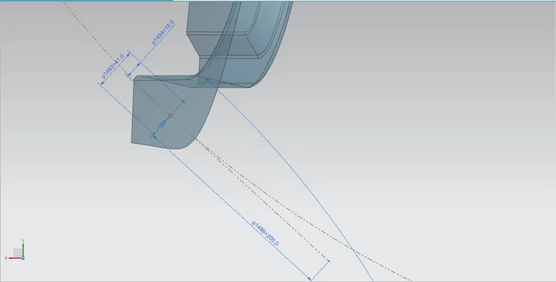
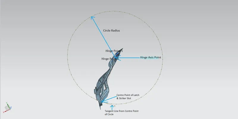
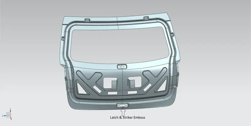
- The same procedure of creating Hinge Emboss is used for creating the Latch & Striker Emboss. The Latch & Striker Emboss image is shown below
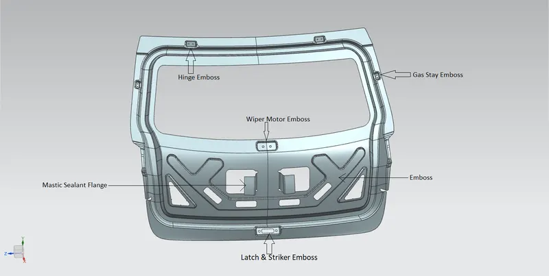
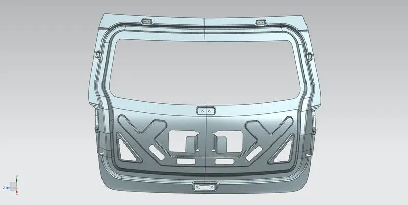
- Then the inner panel is thickened of 0.75mm using Thicken command.The Inner Panel image is shown below
4.OUTER PANEL CREATION-UPPER:
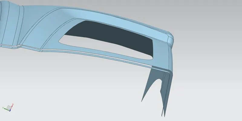
- Offset the surface to a distance of 2.65mm (3x0.75+2x0.2) so that 0.2mm of clearance can be given in between the surfaces.
- Then offset the curve of offset syrface edges using Offset Curve in Face command.
- Then trim the sheet with the offseted curve using Trim Sheet command. The image is shown below
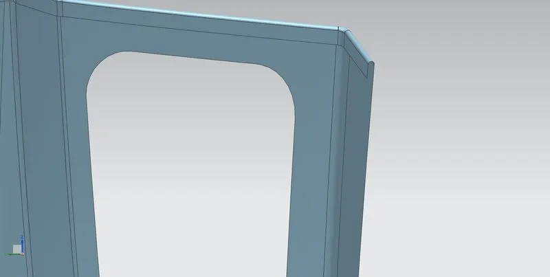
- Then the extension is done to the Orginal surface using Law Extension command.
- Then using Face Blend command and Three face option the Heming is created. The image of Heming is shown below
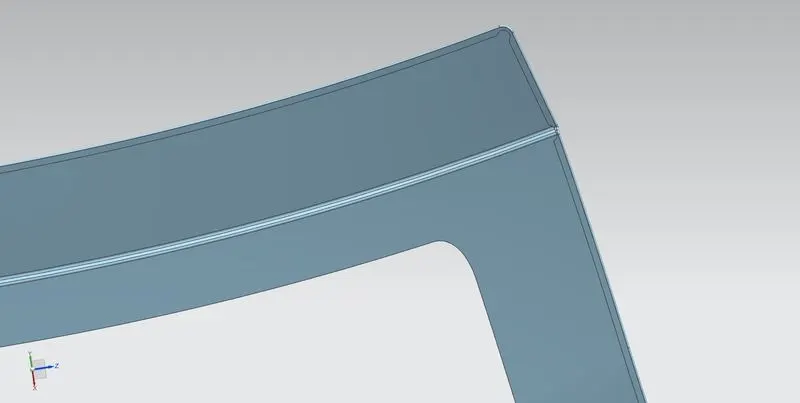
- Then the Relief is created on coners of the heming surfaces by using Curve on Surfaces and Trim Sheet command.
- Reliefs has been given in the corner areas for the easy manufacturability. The image of relief is shown below
- Then the corners are blended using Bridge Curve and Trim Sheet command.
- Then surface in mirrored using Mirror Geomentry command.
- The both surfaces are joinned using Sew command.
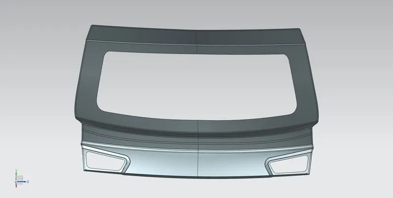
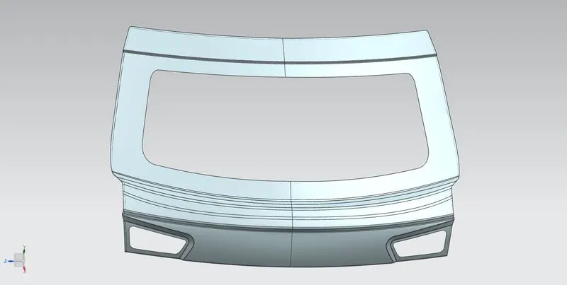
- Then the surface is thickened of 0.75mm using Thicken command. The image of Outer Panel Upper is shown below
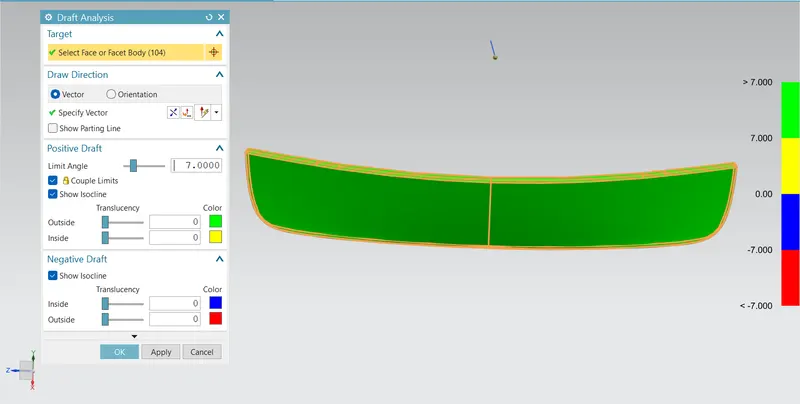
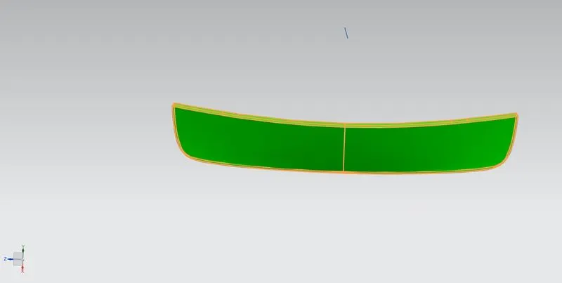
5.OUTER PANEL CREATION-LOWER:
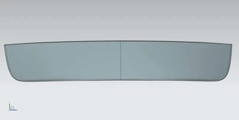
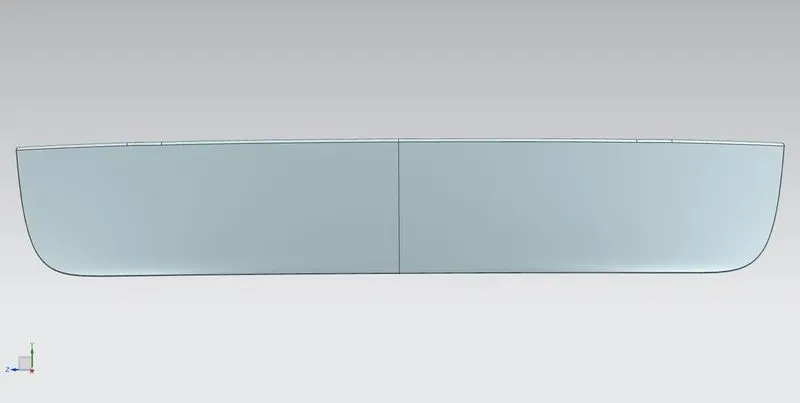
- The same steps of Outer Panel Upper has been followed for creating lower Panel as well. The image of Lower Panel is shown below
6.CREATING REINFORCEMENTS:
- The reinforcements is created by directly offsetting the inner panel surface using the Wave geometry linker.
- Then the smooth surface is created by using Bridge Curve and Trim Sheet command.
- Then the corners are blended using Bridge Curve and Trim Sheet command.
- Then the surface is thickened of 1.5mm using Thicken command.
- All reinforcements are shown below:
Hinge reinforcement:
Gas Stay Reinforcement:
Wiper Motor Reinforcement:
Latch and Striker Reinforcement:
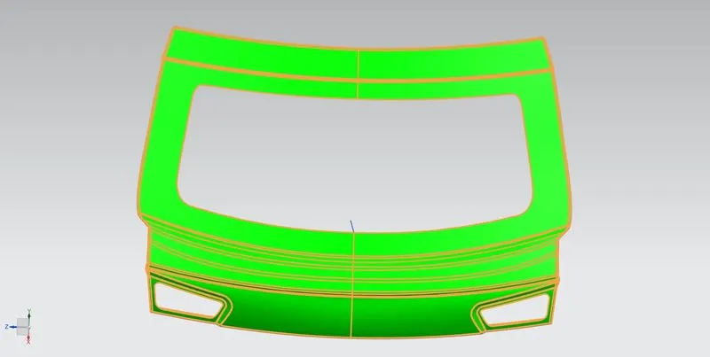
7.Draft Analysis:
Inner Panel:
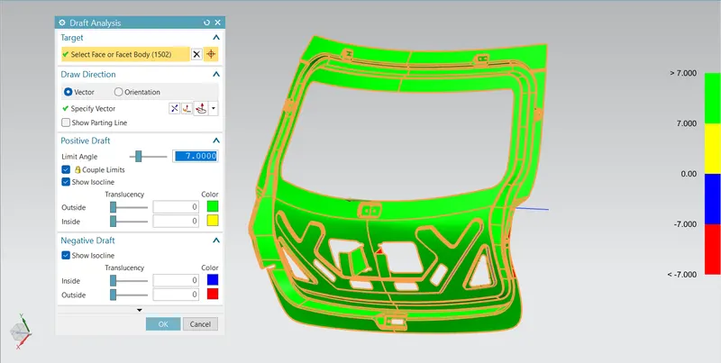
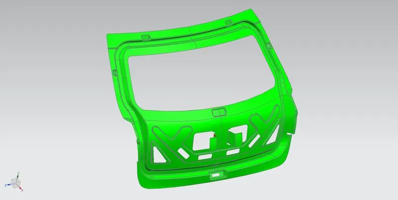
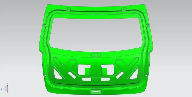
Outer Upper Panel:
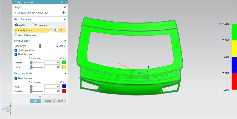
Outer Lower Panel:
8.Final Full Assembly:
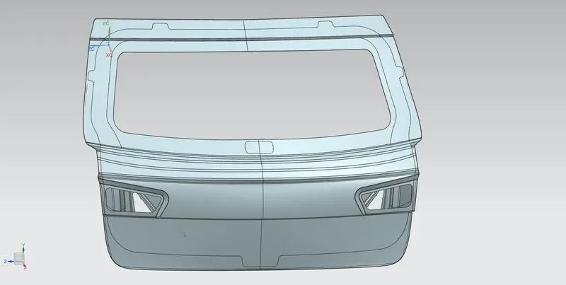
Conclusion:
The Back Door is designed by using the styling surface provided and by using the appropriate design methodologies and the necessary reinforcements and emboss are made in the Back Door.