Speed control of a DC motor using BJT H-bridge with no current shoot up while changing direction using MATLAB
Objective
> Run MATLAB demo ‘Speed control of a DC motor using BJT H-bridge’. Modify the model such that armature current doesn’t shoot up when motor changes direction from forward to reverse.
> Comparison of 'The Four-Quadrant Chopper DC Drive (DC7) block’ with 'H-bridge model'.
> Make a suitable EV model using DC7 block.
Speed control of a DC motor using BJT H-bridge
At first, to run the speed control model of a DC motor using BJT H-bridge in matlab, the command - (power_Hbridge) is run in the command window of MATLAB.
We get a simulink window of the model as shown below
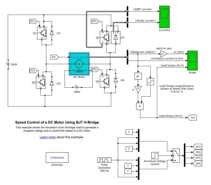
From the above image it is seen that the model consists a motor(5HP 240V 1750rpm field:300V), which is connected to a 240V supply with four bipolar junction transistors(BJT) and diodes, which acts as full bridge rectfiers. The model is know as H-bridge because the connection of the BJT's and diodes are in such a way that switches the polarity of the voltage applied to the motor.
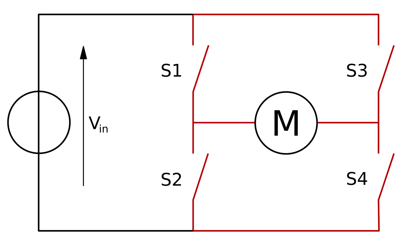
The structure of a simplified H-bridge circuit is given below
The two basic states of the h-bridge is show below
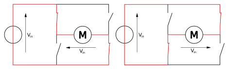
From the above circuits, it shows that voltage can be applied in both the direction when using a H-bridge structure.
The following table summarises the operations corresponding to the switches S1, S2, S3 and S4.
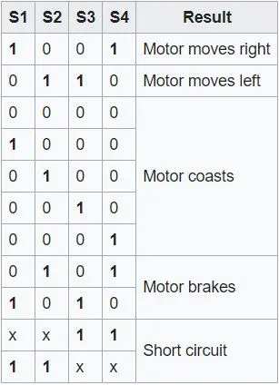
The above table can be similarly compared with the speed control model of the DC motor.
>When Q1, Q4 are connected the motor moves right.
>When Q2, Q3 are connected the motor moves left.
The frequence of the switching is controled by the pulse generator block of the model. The pulse generator consists of inputs such as amplitude, period, pulse width (or) duty cycle and phase delay. The outputs of the pulse generator block are P1, P2, P3 and P4 which are connected to the BJT's. When the pulse width is changed, the results of the pulse generator changes which in turn control the output direction and speed of the motor.
Scopes are attached accordingly to get the graphs of IGBT current, diode current, speed of the motor in (rpm), armature current in (A) and load torque in (N-m). The torque is calculated by using the relation between the torque and speed of a motor.
Simulation of the model with no modifications in the pulse generator block.
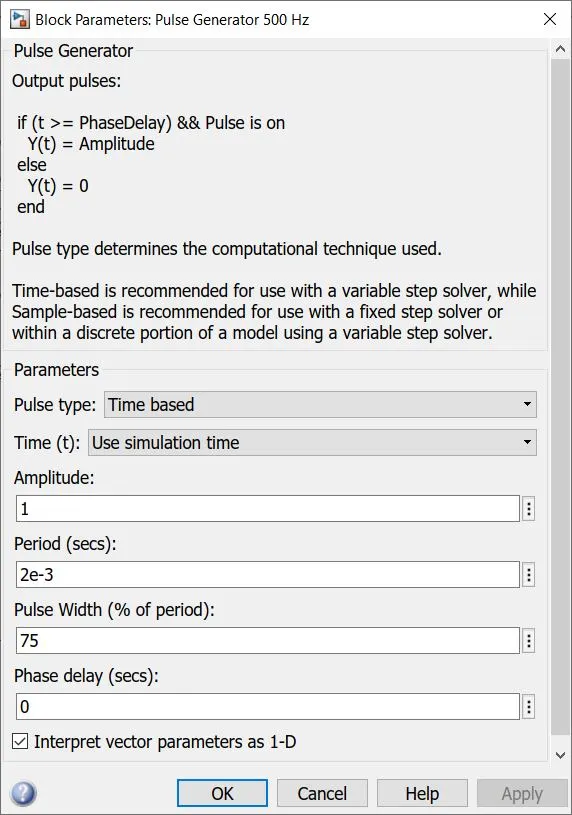
The default value of pulse width is 75. The pulse generator block is given below.
Result of simulation.
The scope consisting the speed of the motor, armature current and load torque of the motor is given below.
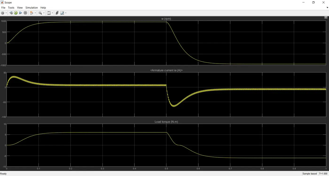
From the result it is seen that the armature current shoots up when the motor is made to change direction at 0.5s of the simulation.
Simulation of the model with change in the pulse generator block.
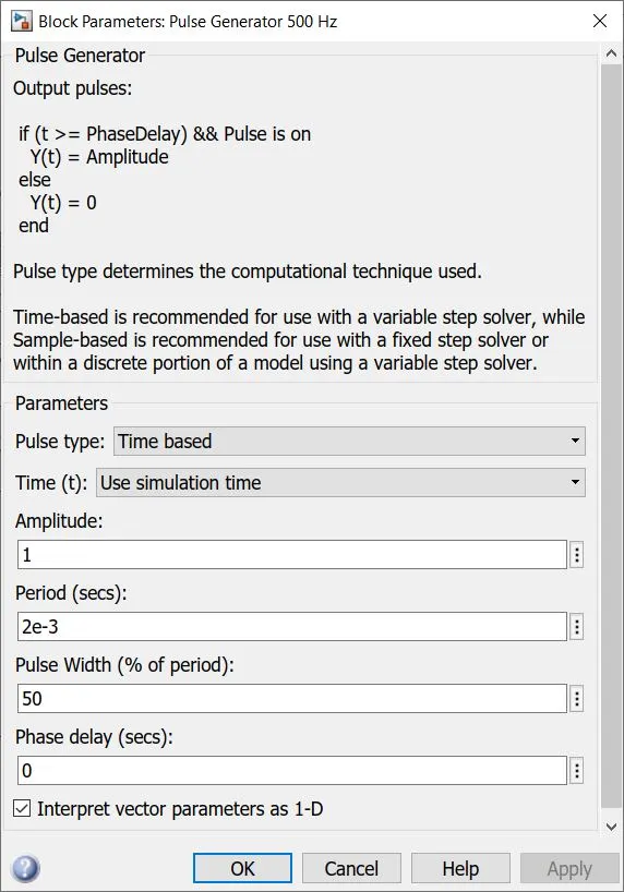
The default value of pulse width 75 is reduced to 50 and then the model is simulated.
Result of simulation.
The scope consisting the speed of the motor, armature current and load torque of the motor is given below.
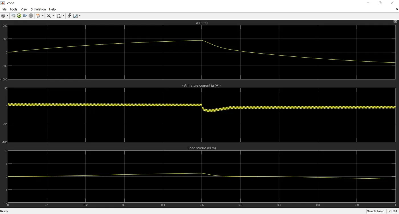
From the result we can see that @ T=0.5 of the simulation the motor changes direction and the current shoot is reduced accordingly. Due to the reduced pulse width, the speed of the motor and the load torque is also reduced.
Simulation of the model with change in the pulse generator block.
The pulse width is again reduced from 50 to 25 percent and then simulated.
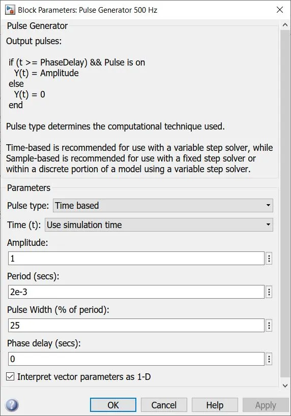
Result of the simulation
The scope consisting the speed of the motor, armature current and load torque of the motor is given below.
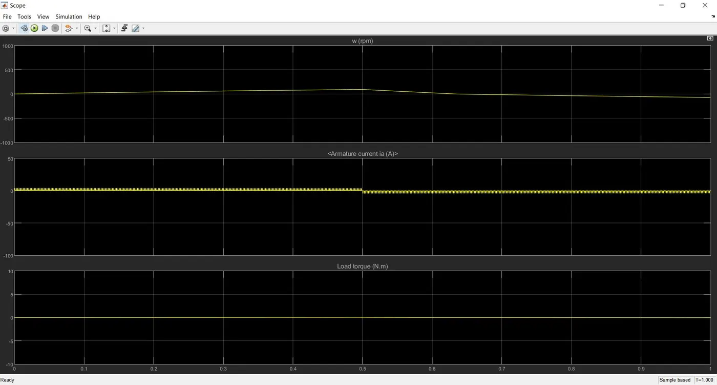
From the result it is see that, the current does not shoot up when the motor changes direction @ T=0.5s of the simulation. The speed of the motor and the load torque in of the motor are low.
Conclusion
From all the simulations it is concluded that, when the duty cycle of the pulse generator block is low then the speed, current and load torque is also low accordingly.
The Four-Quadrant Chopper DC Drive (DC7) block
The Dc7-four quadrent chopper 200 HP DC drive model is opened by running the command (dc7_example) using the command window of MATLAB.
The simulation window of the model is given below.
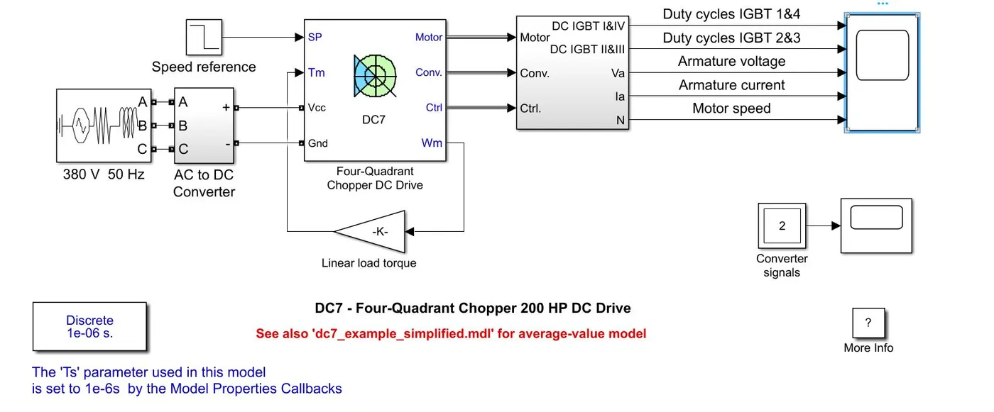
The model consists of a 380V 50Hz three phase AC supply with phase angle 0 which is connected to a converter block. In the converter block it has a rectifier bridge and a braking chopper. The output of the rectfier bridge is connected to the braking chopper. The braking chopper is used to limit the bus voltage during braking mode with a frequency of 4KHz.
A DC7 block situated near the converter block takes inputs such as speed reference, voltage input from AC to DC converter block and load torque value or speed of motor or mechanical rotation port from the motor.
With the above inputs and the standard inputs of the DC machine, controller and converter the outputs are processed in the four quadrent chopper DC drive block. The controller has a schematics by which the speed and current are controlled. The controller schematics are given below.
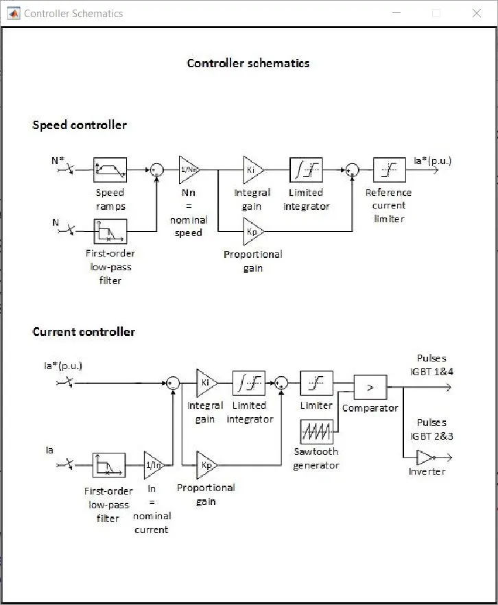
The Four-Quadrant Chopper DC Drive is given below
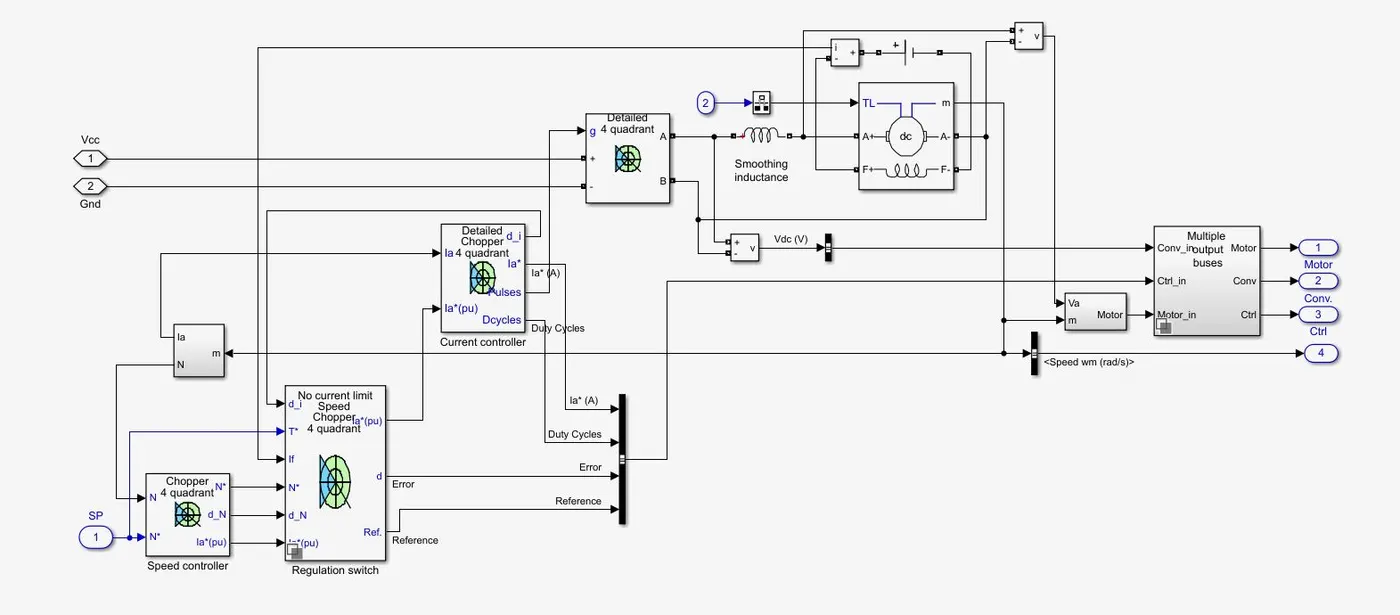
The reference speed is given to the speed regulator and then to the current regulator. The electromagnetic torque required to reach the desired speed is obtained. The IGBT's 1 and 4 are opposite to the IGBT's 2 and 3. They generate the average armature voltage needed to obtain the required armature current. A smoothing inductance is placed in series with the armature current to limit the amplitude of the current oscillation.
Then the signal of motor, controller and converter are given to a subsystem block using a bus operator.
Outputs of armature current, armature voltage and speed are given by the motor and the outputs of current, reference speed, IGBT 1&4 and IGBT 2&3 are given by controller. The converter signal is terminated.
By using the Mux operator the two signals of current from motor and controller are made into one common signal and the speed of the motor and reference speed from motor and controller respectively are made into one common signal.
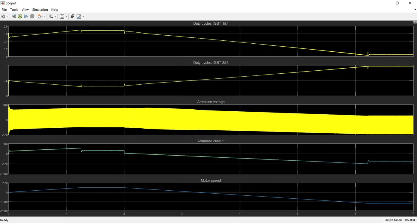
Now, The duty cycle of IGBT 1&4, duty cycle of 2&3, Armature voltage, aramture current and speed are plotted using a scope.
By simulating the model the results plot from the scope is given below.
Comparison of The Four-Quadrant Chopper DC Drive (DC7) block with H-bridge
>The simulation is continuous in H-bridge whereas the simulation is discrete using a four quadrent chopper DC drive.
>Since H-bridge uses continuous simulation the simulation time is less when compared to DC7 block.
>Direction of the motor can be changed by changing the polarity in a H-bridge structured circuit and, the direction of the motor can be changed in a four quadrant chopper DC drive by changing the input signal to the DC7 block.
>Use of snubber in H-bridge circuit is not required but it is required for the DC7 block. This is due to the rapid raise in the voltage when a change in the input signal occurs in the DC7 block.
>Speed of the motor can be varied by variying the duty cycle of the motor in H-bridge circuit. In the DC drive with DC7 block speed of the motor can be varied by the input signal or speed reference.
>Regenerative braking can be done in H-bridge circuit but cannot be done in the four quadrant chopper DC drive.
Suitable EV model using DC7 block
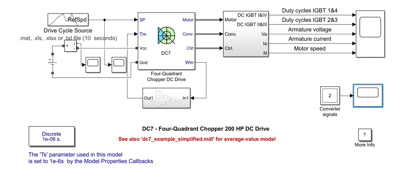
The Four quadrent DC drive model is modified to make a suitable EV model using DC7 block, it requires a DC battery input, drive cycle data for the vehicle and torque load characteristic of the vehicle.
The three phase AC supply, speed reference and the AC to DC converter blocks are removed from the four quadrent DC drive model
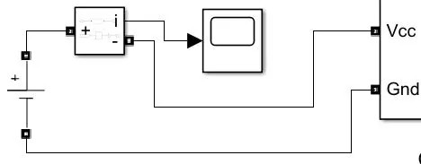
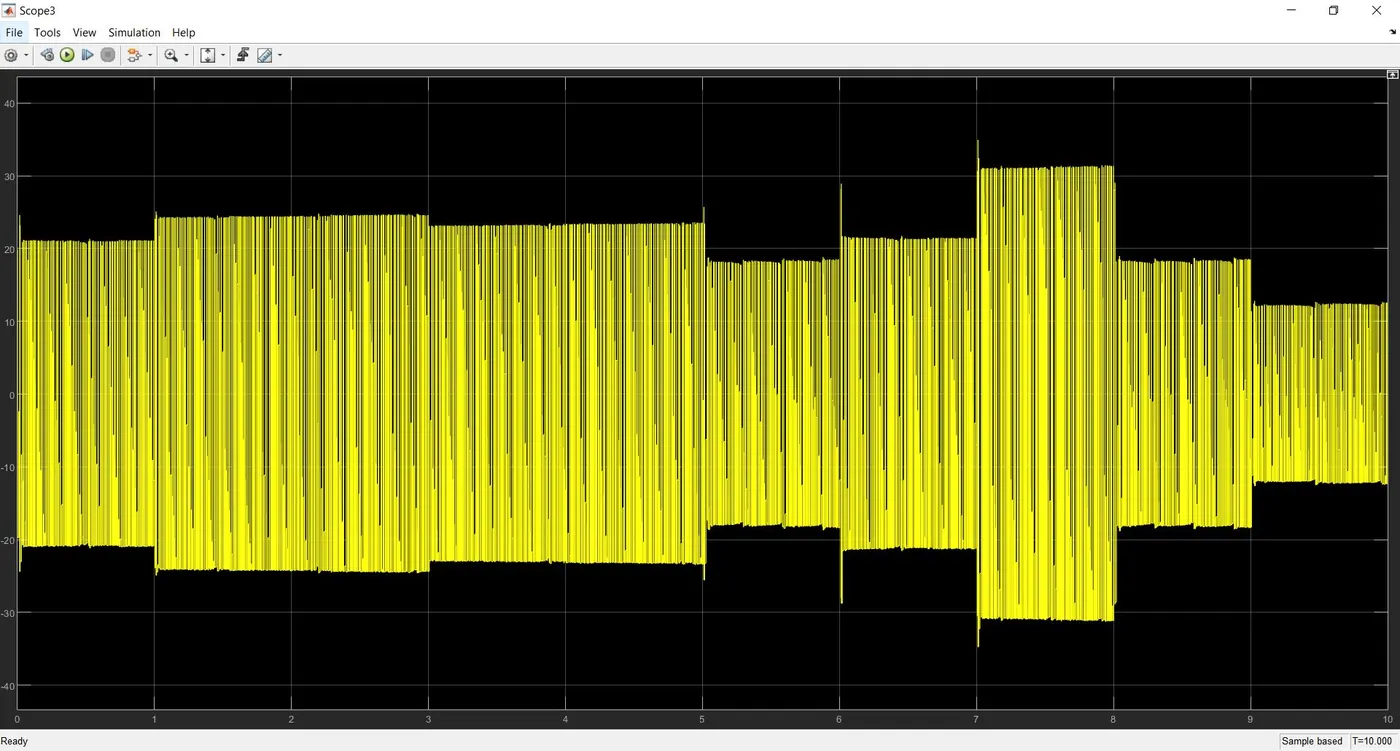
For the battery input, a DC voltage block is added to the system with amplitude voltage 515V. The positive of the DC supply block is connected to a current measurement block by which the current output is measured and ploted using a scope. The positive and negative terminals are connected with the Vcc and Gnd of the DC7 block respectively.
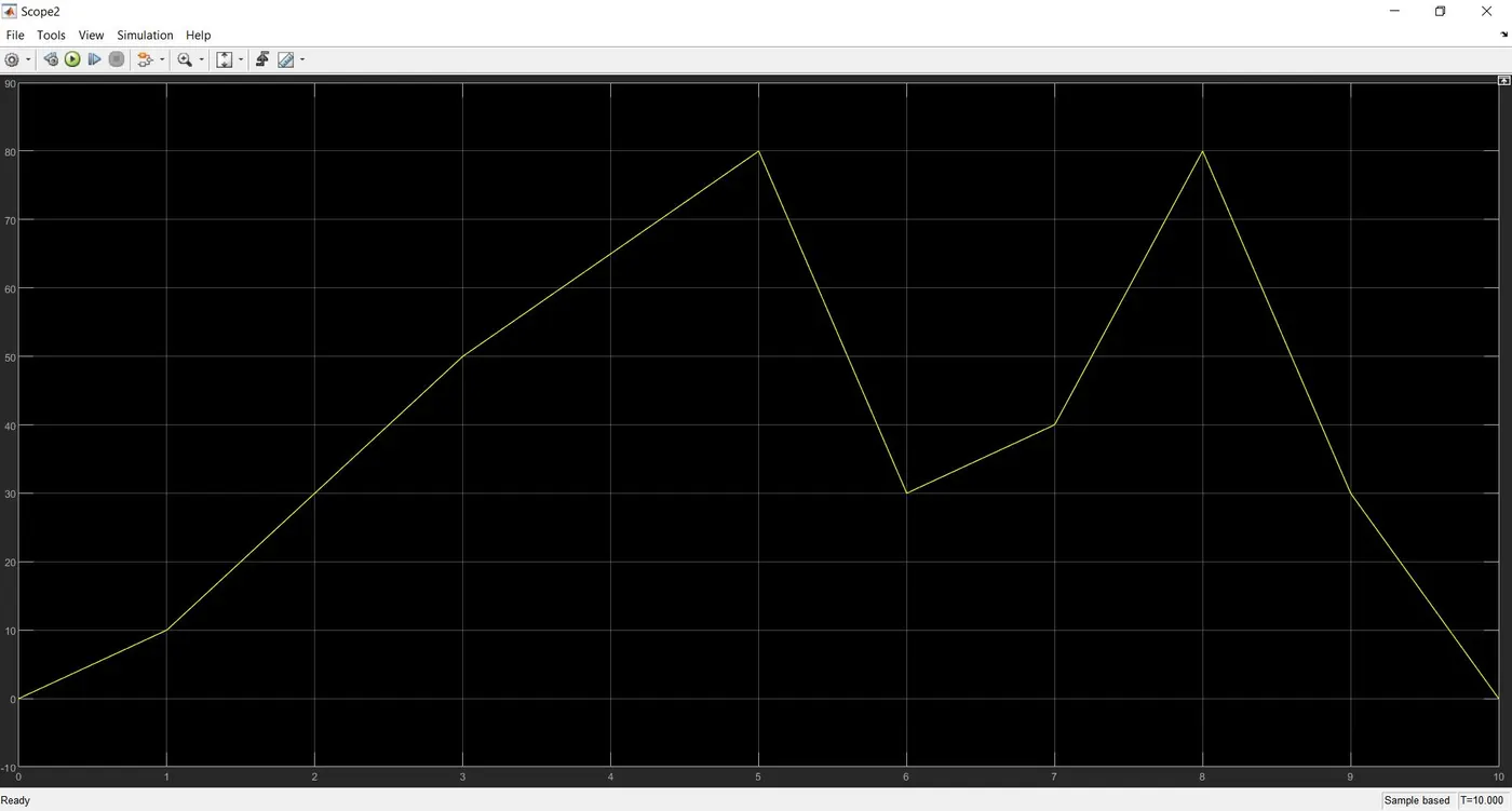
The speed reference block of the four quadrent DC drive model is replaced with a drive cycle block. The drive cycle data are prepared using an excel sheet. In the drive cycle block the created spreadsheet is selected as input drive cycle. A scope is attached to get the plot of the drive cycle. The excel link is given below.
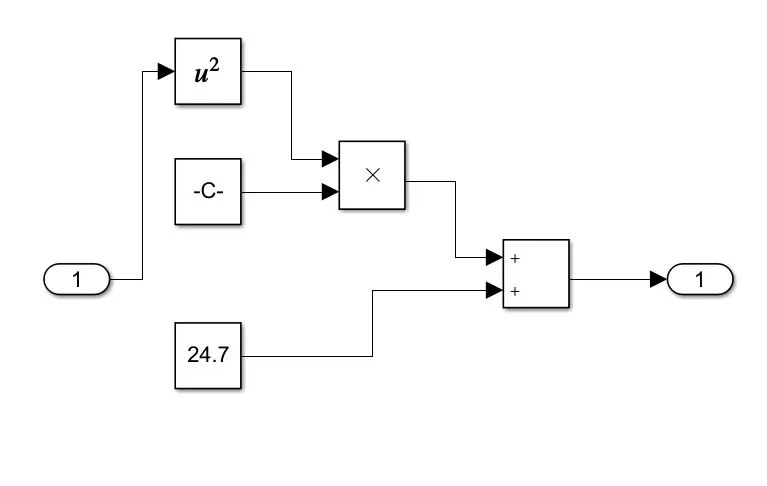
Torque load characteristic of the vehicle is said to be,
T = 24.7+0.0051(w^2)
A subsystem for calculating the torque (Tm) with speed of the motor (w) given as input created as shown below.
The simulink window after changing the four quadrent DC drive model accordingly is show below.
The results of simulating the above EV model using the DC7 block
Drive cycle plot
Current output plot from DC voltage supply
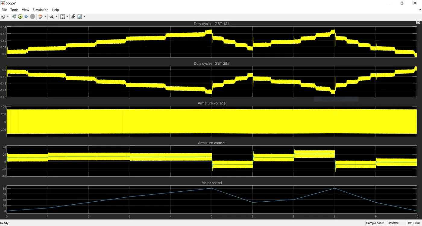
Resultant plot of IGBT 1&4, IGBT 2&3, current, voltage and speed of motor
Duty cycle IGBT 1&4 plot
It is seen that duty cycle increases as the vehicle accelerates and decreases when the vehicle decelerates.
Duty cycle IGBT 2&3 plot
The duty cycle decreases as the vehicle accelerates and increases during deceleration of the vehicle.
Armature voltage
The armature voltage of the motor is approximately constant throughout the simulation
Armature current
The current increases as the vehicle accelerates and decreases when the vehicle decelerates.
At T=5s, the speed of the vehicle reduces and the plot shows that the current at that point goes negative. The negative current shows that the motor tends to rotate in the opposite direction in order to decrease the speed of the vehicle according to the drive cycle input.
Motor speed
From the plot it is clearly seen that the motor speed matches the drive cycle input.
Conclusion
Thus a suitable EV model is made using the DC7 block and simulated in which the vehicle speed matches the drive cycle data given to the model successfully.