DC Motor Control
OBJECTIVES:
- Understanding the difference between 4 quadrant DC drives and H-bridge DC drives
- Constructing the inputs needed to run a 4 quadrant chopper and analysing the output
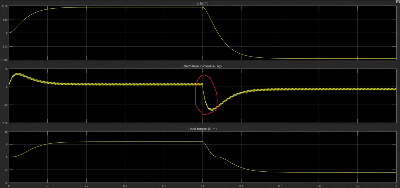
1) Run MATLAB demo ‘Speed control of a DC motor using BJT H-bridge’. Modify the model such that armature current doesn’t shoot up when motor changes direction from forward to reverse.
Why does armature current shoot up when motor changes direction or when the motor is starting?
Voltage to power the DC motor:
`V_s = I_aR_a + E_b` [where `E_b prop omega]`
When the motor is just starting, the armature isnt rotating fast enough to induce back EMF, which means:
`V_s=I_aR_a` --> `I_a = V_s/R_a` instead of `(V_s-E_b)/R_a` --> which is why the initial inrush current shoots up
The same applies when the motor changes direction from forward to reverse. Even if it is 'hard-switching' (i.e. the motor RPM doesn't need to approach zero to change its direction when vehicle direction is switching), the RPM will be zero for a fraction of a second where `E_b` is zero for that instant, which is why the armature current shoots up.
What are the implications of high current inflow? Why is it bad?
The sudden inrush and surge of current can damage the internal circuit and rotor windings, which will shorten the lifespan of the DC motor.
To minimize the inrush of current (since `I_a = V_s/R_a`):
`V_(output (avg)` = `V_s*d` [where d is duty cycle]
Varying the duty cycle through power electronics techniques, such as changing the transistor's switching frequency to match the requirements, will help reduce the output voltage.
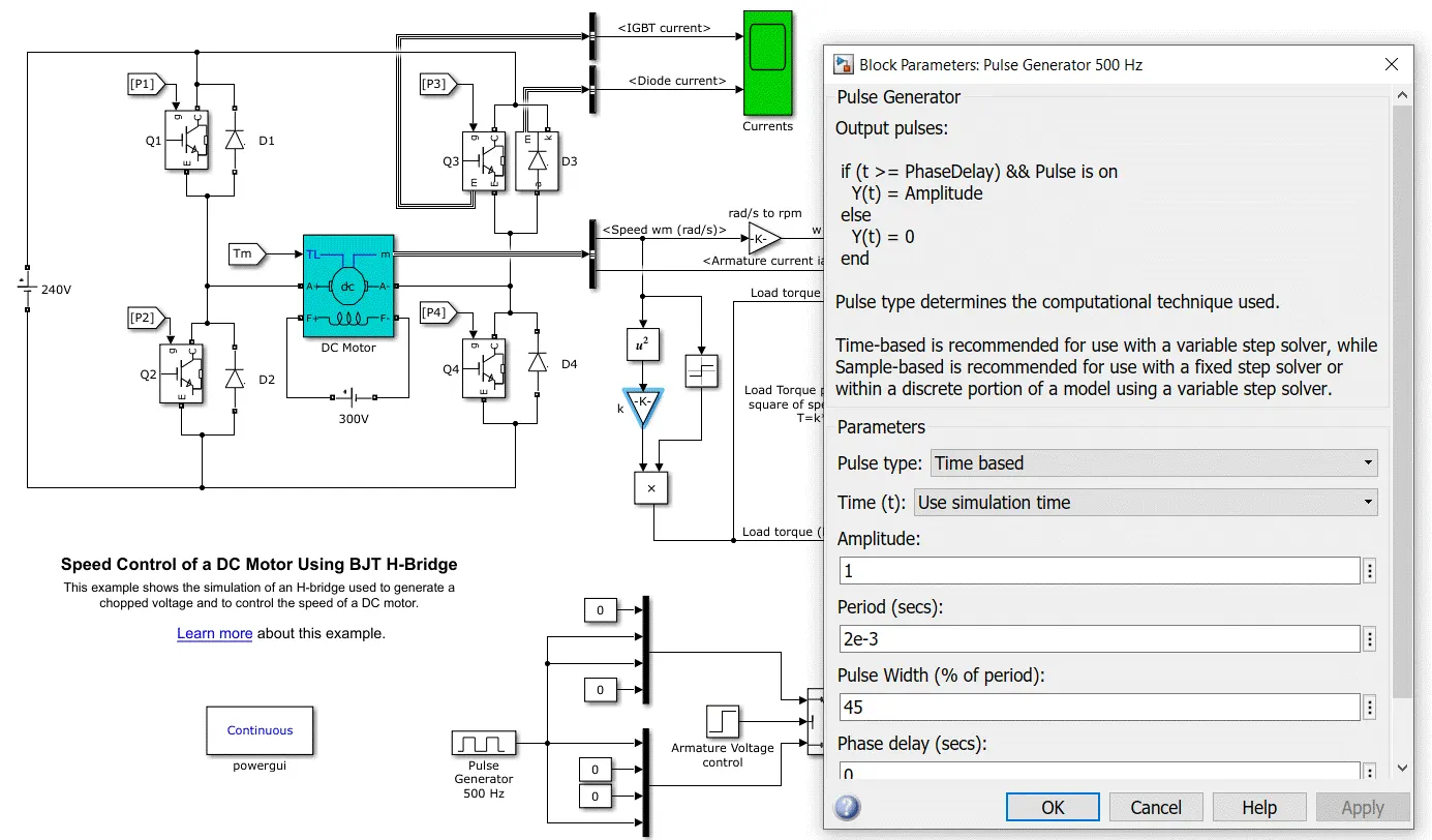
Changing duty cycle from an initial 75% to 45% (pulse width):
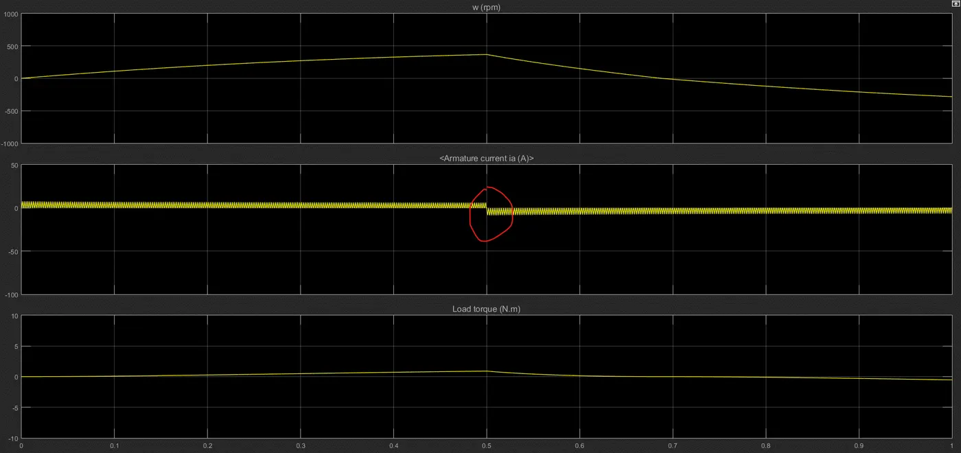
Output: armature current does not shoot up anymore
An alternate solution?
Looking at the formula: `I_a = V_s/R_a`
Another thing that could be varied other than output voltage would be the total resistance of the motor
A variable resistor `R_v` connected in series with the existing resistor `R_a`, which decreases to a negligible value as the armature revs up and back EMF comes into play --> `I_a = V/(R_a +R_v)`
But why isn't this preferred?
- Any kind of resistance in a circuit leads to heat dissipative losses, so an extra variable resistor will lead to significant power losses especially when the resistance it is carrying is high (this will happen during the situation when output voltage required is low)
- Slower compared to power electronics - an exact amount of output voltage required can be obtained by altering the duty cycle through simply varying the ON/OFF duration, but with variable resistor it is a more gradual process to achieve that exact output, as it will be steadily increasing/decreasing its resistance depending on what is required. This isn't feasible for instantaneous changes and precise applications.
2) Refer to help section of ‘The Four-Quadrant Chopper DC Drive (DC7) block’. Compare it with H-bridge model.
| H-bridge drive | Four-Quadrant drive |
|
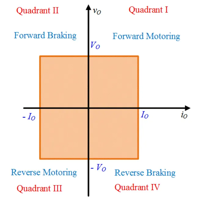
- Can only operate in two quadrants: power can only flow from source to load, which means that the motor cannot play a role during braking operations - One way power flow means recovering energy through regenerative braking is not possible - No PI regulators are used - Polarity of the current is reversed to change the direction of motor rotation - Applications include robotics and electromechanical devices |
- Can be operated in all four quadrants: power can flow from source to load or load to source, which means the motor can act as a generator too - Due to generative properties, regenerative braking is possible - Two PI regulators are used to reach the desired speed and control the armature current - Current signals (that result from drive cycle or reference values) are interrupted by one another to change the motor direction - Applications include automobiles |
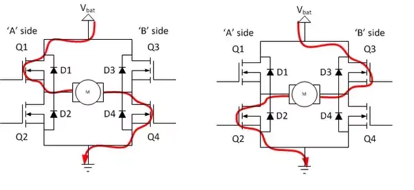 Four BJT transistors with the DC motor in the middle forming an 'H', which is why it is called H-bridge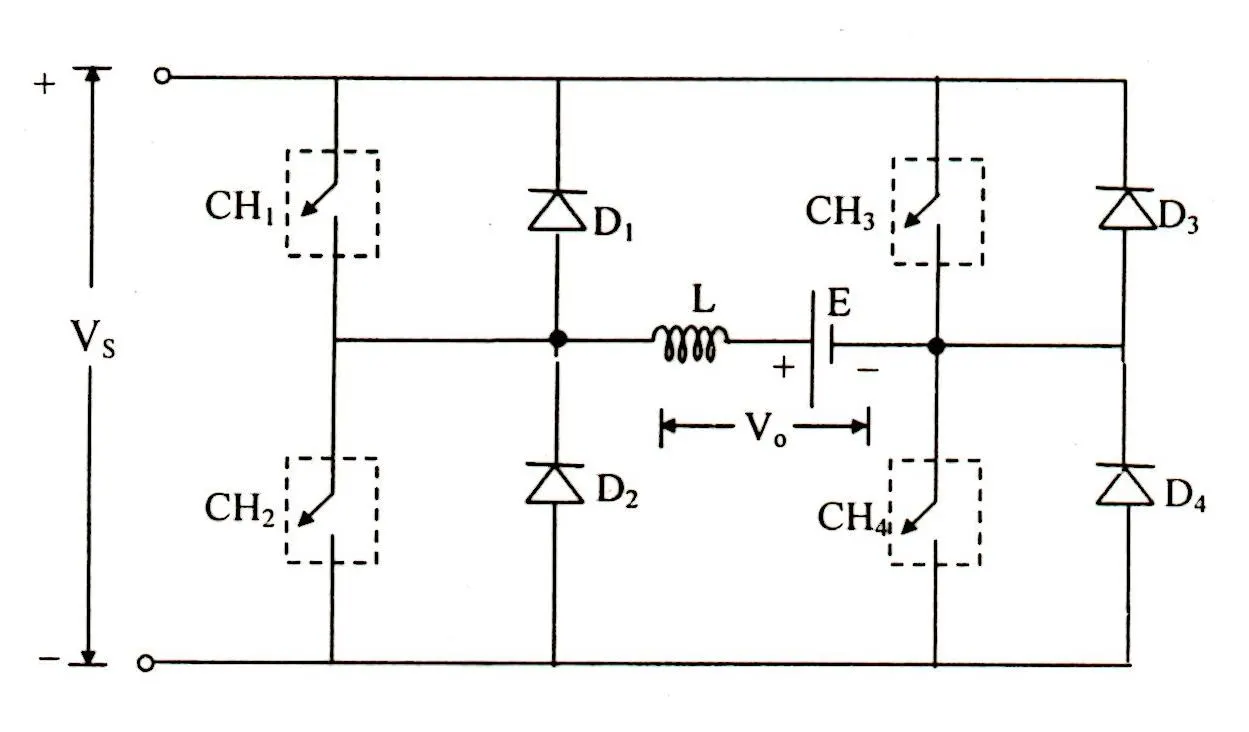
3) Make a suitable EV model using DC7 block and make result report.
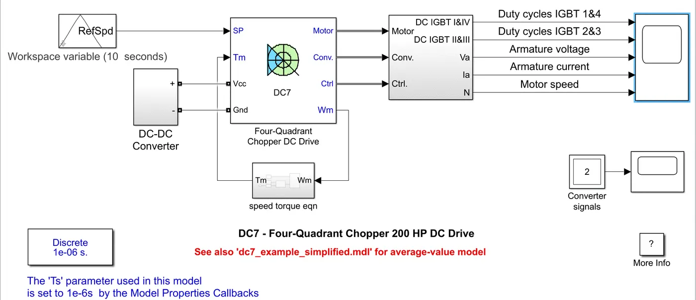
- Drive cycle inputted
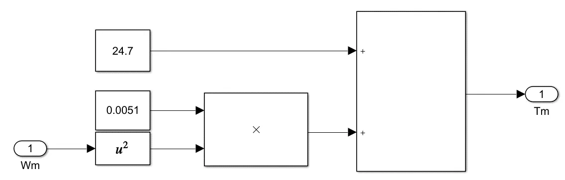
- Speed-torque characteristic equation given to the DC drive
- A DC-DC converter (chopper) implemented
Speed-torque characteristic equation: `T_m = 24.7+0.0051omega_m^2`
A DC-DC converter (chopper) implemented:
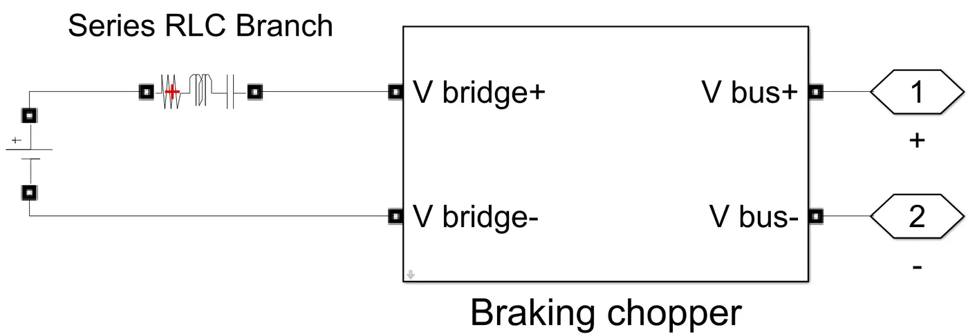
- 100V battery
- 1 Ohm resistor (inductance and capacitance set to 0)
- Chopper to control DC voltage
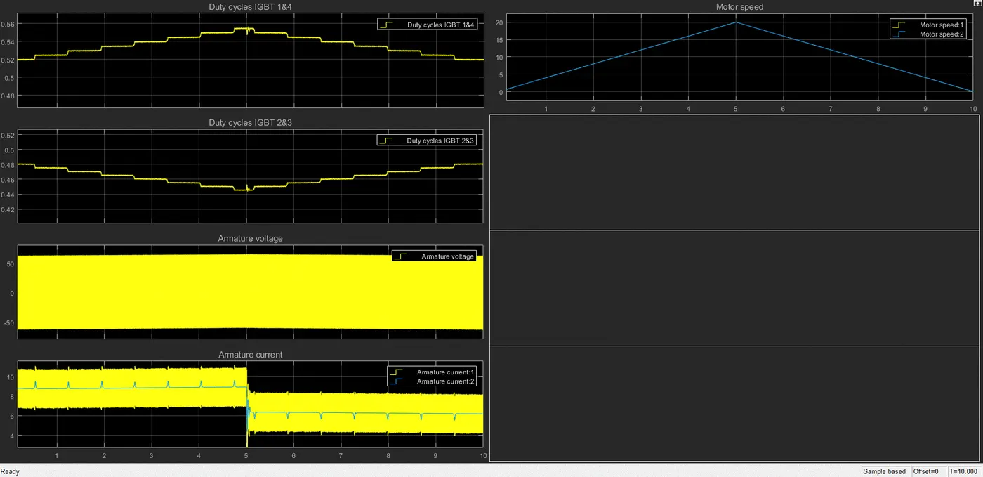
- The increase and decrease in duty cycle corresponds to the power requirement by the motor, so it can achieve a certain angular speed for the vehicle. When the duty cycle increases, the voltage supplied to the motor is more, and so the motor is able to run at higher RPM.
- Plot 1: When motor speed is increasing until 5 seconds, the duty cycle of IGBT 1&4 is also increasing
- Plot 2: When motor speed is decreasing from 5-10 seconds, the duty cycle of IGBT 2&3 is decreasing by the same amount that IGBT 1&4 is increasing (a complete reflection of Plot 1).
- Plot 3 and 4: The armature voltage is fluctuating between 50V and -50V at extremely high frequency as is evident. This is because of the power switch between IGBT 1&4 and IGBT 2&3, which leads to the polarity of the voltage reversing as it flows through the armature. While motor speed in increasing until 5 seconds, more voltage and current are required since both are proportional to each other. While the voltage is fluctuating between peak positive and negative values, armature current is positive all along. This is because as per the drive cycle input, the motor is operating in 2 quadrants only (forward motoring and braking). If all 4 quadrants were to be explored, more conclusions could be deduced.
- Plot 5: this is just a translation of the input reference speed (drive cycle) provided into a plot