DC MOTOR CHARACTERISTICS
AIM
Understandig DC MACHINE or MOTOR
OBJECTIVE-1→">→→Implement DC machine torque speed characteristics equations in MATLAB script file. It asks user to input data and plots speed (RPM) versus torque (Nm). Submit the .m file for evaluation and attach the screenshots of all the required plots
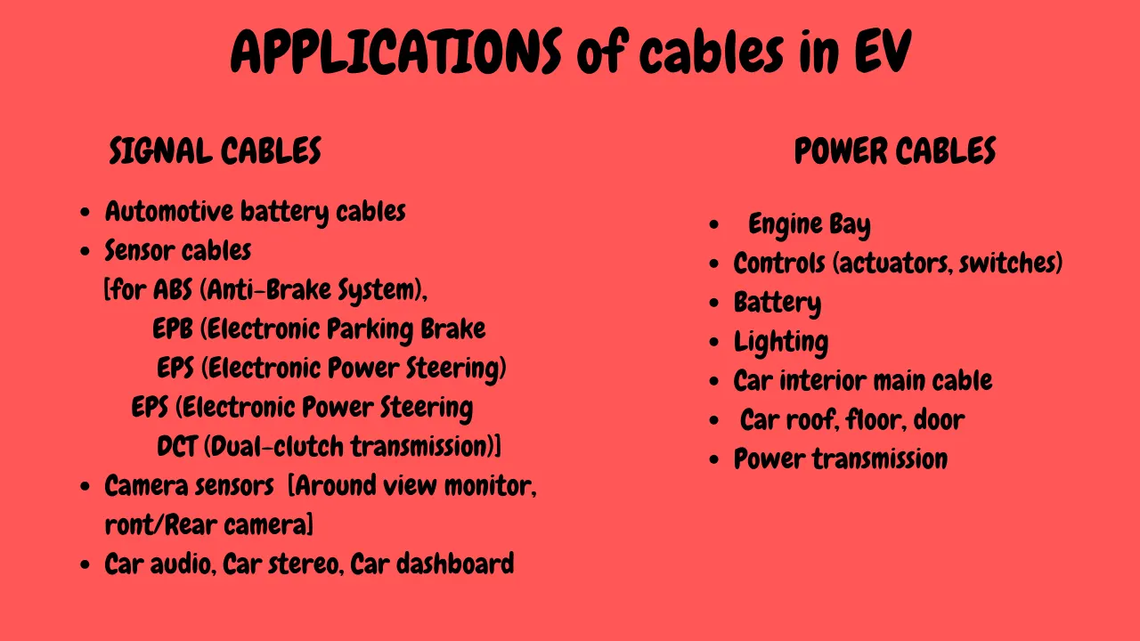
OBJECTIVE-2→">→→How can you distinguish between power cables and signal cables and also prepare a table where these cables are used in the wiring of an electric vehicle?
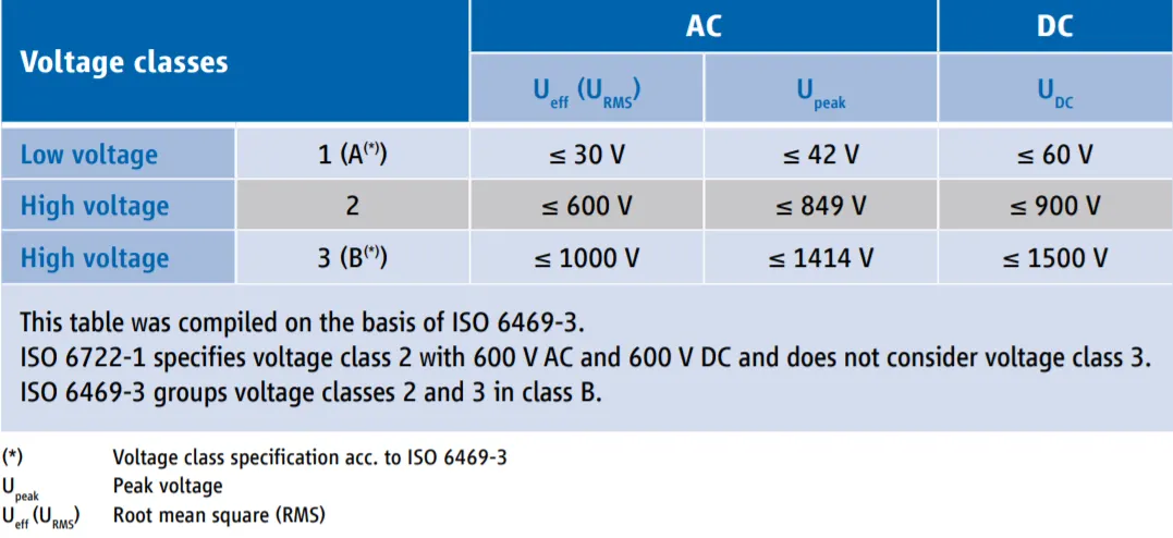
OBJECTIVE-3→">→→What voltage levels are considered as high & low for a battery pack of electric vehicle
OBJECTIVE-1→">→→Implement DC machine torque speed characteristics equations in MATLAB script file. It asks user to input data and plots speed (RPM) versus torque (Nm). Submit the .m file for evaluation and attach the screenshots of all the required plots
THEORY
what is a DC Motor? The DC motor is the motor which converts the direct current into the mechanical work. It works on the principle of Lorentz Law, which states that “the current carrying conductor placed in a magnetic and electric field experience a force”. And that force is the Lorentz Force.
There are 4 major types of DCmotor and they are,
- Series DC Motor
- Permanent Magnet DC Motor
- Shunt/Parallel DC Motor
- Compound DC Motors
Construction of DC motor -
Before understanding the working of DC motor first, we have to know about their construction. There are two main parts of the DC motor.
- Armature
- Stator
The rotating part is the armature and the Stator is their stationary part. The armature coil is connected to the DC supply.
The armature coil consists the commutators and brushes. The commutator converts the AC induces in the armature into DC and brushes transfer the current from rotating part of the motor to the stationary external load. The armature places between the north and south pole of the permanent or electromagnet
Working Principle of DC Motor - A DC motor is an electrical machine which converts electrical energy into mechanical energy. The basic working principle of the DC motor is that whenever a current carrying conductor places in the magnetic field, it experiences a mechanical force. Fleming’s left-hand rule and its magnitude decide the direction of this force.
Fleming's Left Hand Rule - If we stretch the first finger, second finger and thumb of our left hand to be perpendicular to each other, and first finger represents the direction of the magnetic field, the second finger represents the direction of the current, then the thumb represents the direction of the force experienced by the current carrying conductor.
Back-EMF of DC Motor - According to the fundamental law of nature, no energy conversion is possible until there is something to oppose the conversion. In case of generators, magnetic drag provides this opposition, but in the case of dc motors, there is back emf. Presence of the back emf makes a dc motor ‘self-regulating’.When the armature of a motor is rotating, the conductors are also cutting the magnetic flux lines and hence according to the Faraday's Law of Electromagnetic Induction, an emf induces in the armature conductors.The direction of this induced emf is such that it opposes the armature current (Ia). The circuit diagram below illustrates the direction of the back emf and armature current.
Significance of Back-Emf - Magnitude of back emf is directly proportional to speed of the motor. Consider the load on a dc motor is suddenly reduced. In this case, required torque will be small as compared to the current torque. Speed of the motor will start increasing due to the excess torque. Hence, being proportional to the speed, magnitude of the back emf will also increase. With increasing back emf armature current will start decreasing. Torque being proportional to the armature current, it will also decrease until it becomes sufficient for the load. Thus, speed of the motor will regulate.
On the other hand, if a dc motor is suddenly loaded, the load will cause decrease in the speed. Due to decrease in speed, back emf will also decrease which allows more armature current. Due to increase in armature current the torque will increase to fulfill the load requirement.
The important characteristics of DC Motor are -
- Speed-Armature Current Characteristics
- Torque-Armature Current Characteristics
- Speed-Torque Current Characteristics
NOTE - Here i am discussing only the speed-torque chara.
EQUATIONS USED
The torque equation can be given as - T=V⋅kФRa-(kФ)2Ra⋅N">T=V⋅kФRa−(kФ)2Ra⋅NT=V⋅kФRa-(kФ)2Ra⋅N
where, kФ=Eb⋅602πN">kФ=Eb⋅602πNkФ=Eb⋅602πN
T - Torque (Nm)
V - Voltage (Volts)
kϕ">kϕkϕ - constant of propaortionality
Ra - Armature Current
N - Motor Speed (rpm)
Eb - Back Emf (Volts)
TORQUE SPEED CHARACTERISTICS
Here i have defined the program in such a way that it will ask for user inputs, such as voltage, speed, armature resistance, armature current in aseparate dialogue box. The user can input as many values as he wants. Followed by the values are automatically calculated based on the defined torque equation. Here i have given the back emf (Eb)value as 1, for test purposes. Then atlast, the plot for speed-torque characteristics is defined.
% MATLAB PROGRAM FOR CALCULATING THE DC MOTOR SPEED TORQUE CHARACTERISTICS

close all                                         % closes all the existing window in the memory
clear all                                         % clear the workspace
clc                                               % clears the command window

prompt={'Enter the constant VOLTAGE (V) in square brackets:',
        'Enter the Speed(RPM) in square brackets:',                                        % createsa variable to store the questions to ask with the user
        'Enter the ARMATURE RESISTANCE(ohms) in square brackets',
        'Enter the ARMATURE CURRENT in square brackets:'};

tittle='TORQUE Calculator';                                                                % just a variable storing a string
answer=inputdlg(prompt,tittle)                                                             % creates a dialog box to enter the user defined values

V=str2num(answer{1});                                                                      % variable storing the voltage

N=str2num(answer{2});                                                                      % variable storing the speed in rpm

Ra=str2num(answer{3});                                                                     % variable storing the armature resistance

Ia=str2num(answer{4});                                                                     % variable storing the armature current

%Eb=V-(Ia.*Ra);                                                                            % back emf equation
Eb=1;                                                                                      % for testing coditions iam considering Eb =1

Kphi=(Eb*60)./(2*3.14*N);                                                                  % equation to calculate the quantity (K*phi)

T=((60*V-(2*3.14*N.*Kphi)).*Kphi)./(60*Ra)                                                 % calculates the torque


plot(N,T,'color','r');                                                                     % plots the graph between speed and torque
xlabel('speed RPM')                                                                        % xaxis is labelled
ylabel('Torque Nm')                                                                        % yaxis is labelled
title('Speed-Torque characteristics')                                                      % gives the tittle
OUTPUT -
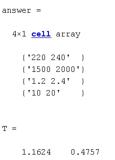
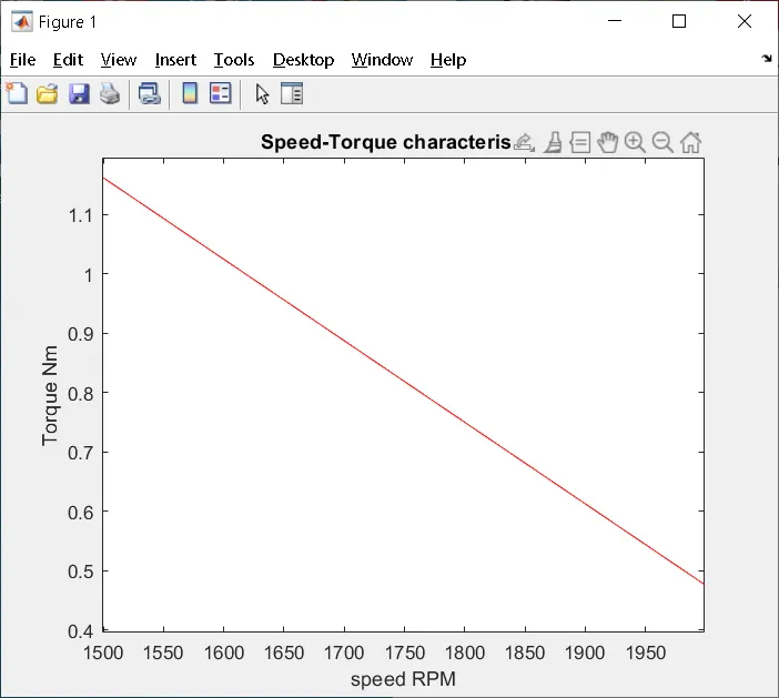
MATLAB FILES - https://drive.google.com/drive/folders/1GPyqV3Pf0eTCJCckc8gzOVUemuD84uc9?usp=sharing
------------------------------------------------------------------------------------------------------------------------------------------------------------------------------------------------------------------------------------------------------------------------------------------------------------------------------------------------------------------------------------------------------------------------------------------------------------------------------------------------------------------------------------------------------------------------------------------------------------------------------------------------------------------------------------------------------------------------------
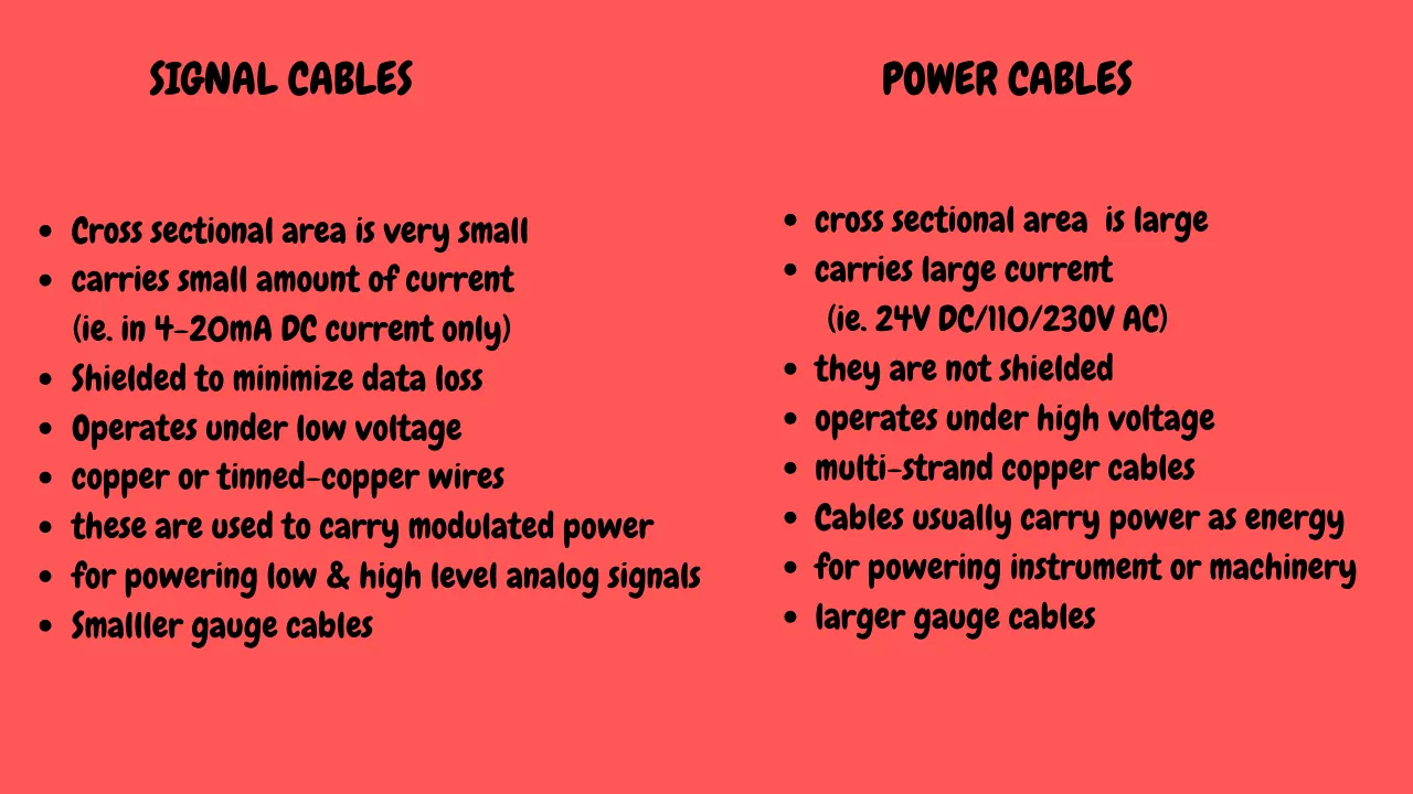
OBJECTIVE-2→">→→How can you distinguish between power cables and signal cables and also prepare a table where these cables are used in the wiring of an electric vehicle?
A car's wiring has to distribute power from the battery to devices located all over the car. It also has to transmit data on a data bus, as well as a variety of digital and analog signals from switches and sensors.This means that there are many different types of wires in your car. Some wires that transmit signals from switches or sensors carry almost no current. Those that provide power to large electric motors carry lots of current. If too much current goes through a wire, it can overheat and melt. The amount of current that a wire can handle depends on its length, composition, size and how it is bundled
- Length - Each type of wire has a certain amount of resistance per foot -- the longer the wire, the larger the resistance. If the resistance is too high, a lot of the power that flows down the wire will be wasted; the energy lost as heat builds up in the wire. Ultimately, heat build-up limits the current-carrying capacity of the wire, as the temperature must not get hot enough to melt the insulation.
- Composition - Automotive wire is usually composed of fine copper strands. Generally, the finer the strands, the lower the resistance and the more current the wire can carry. The type of copper used has an effect on the resistance of the wire, too.
- Wire gauge - The wire gauge, or size of the wire, also determines how much resistance the wire has. The larger the wire, the less resistance. The smaller the gauge, the larger the wire -- so a 16-gauge wire is bigger than a 24-gauge wire. Wire gauges go all the way down to zero, which is also called 1/0 (one aught). Even bigger than 1/0 is 00 (2/0, or two aught), and so on. The diameter of a 4/0 (four aught) wire is almost half an inch (1.27 cm).
- Bundling - The way a wire is bundled affects how well it can dissipate heat. If the wire is in a bundle with 50 other wires, it can carry a lot less current than if it were the only wire in the bundle.
What is a cable? Like a pipe that carries water to your home, or waste from it, the role of cable is to carry an audio or video signal from one device to another. Cables carry signals between DVD players and TVs, stereo receiver's and speakers, and computers and video projectors. Cables are messegers that dont process the signals provided to them
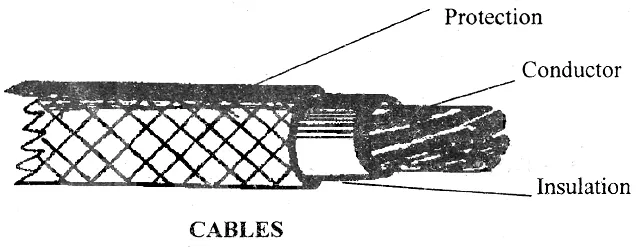
What does a cable consists of? Cables are mad eup of 3 basic parts- conductor, shielding and connector. The conductor is the wire that actually carries the signal. One or more layers of shielding prevent the wire fiom acting as an antenna that picks up the radio frequency interference and electromagnetic interference. The connector is the plug at the end of the cable that connects to your device.
Wiring of Electric Vehicles
Electric vehicle wiring is similar to battery cables in conventional vehicles, except that EV cables are shielded. The shield is typically foil covered by a tinned-copper braided shield.The shielding is required to reduce electromagnetic and radio frequency interference (EMI/RFI) caused by the electrical noise generated by the high frequency switching that takes place in the inverter.
In traditional vehicles, the most cost-effective method of suppressing EMI/RFI noise is through the use of components such as capacitors, inductors and diodes. But, shielding electronics and wiring becomes more cost-effective solution in HEV's because the traditional suppression components required would be too large and heavy to be practical. Hence this brings us to the need of having perfect wiring, to make the manufacturing productive.
POWER CABLE
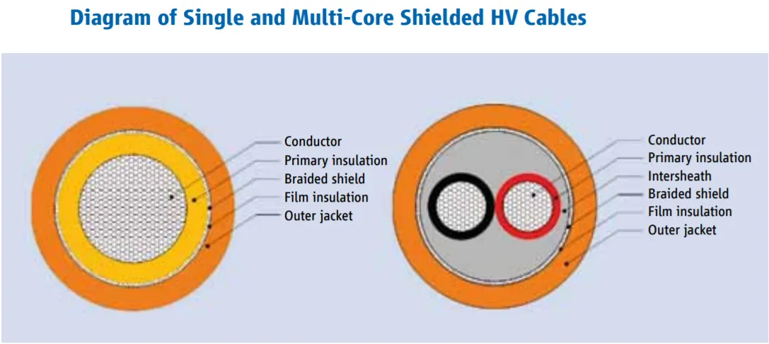
- The electric drivetrain of an HEV or EV is mainly composed of a high-voltage battery, inverters, and motors. They are connected to each other with high-voltage wiring harnesses. The high-voltage wiring harness connecting the high-voltage battery and inverter is called an under-floor wiring harness, and its wire length is relatively long. The high-voltage wiring harness connecting the inverter and motor is called a power cable, and its wire length is relatively short.
The power cable of this development target vehicle connects the inverter and two three-phase alternating current (AC) motors (one used for driving the vehicle and the other for generating electricity). The power cable consists of three thick wires for each motor (six thick wires in total), high-voltage connectors at both ends connected to the inverter and motors, and a shielding layer for shielding electromagnetic noise. In order to apply this power cable to a short distance section between the inverter and motors, it was necessary to reduce its size and weight.
- The charging cable of an EV must bear high voltage when it comes to cahrge the large chunck of battery module of the EV. Hence it should be a power cable to carry on the power needed for charging the vehicle.
REFERENCE
https://www.assemblymag.com/articles/89633-wire-processing-for-electric-cars
https://global-sei.com/technology/tr/bn88/pdf/E88-06.pdf
https://auto.howstuffworks.com/wfc1.htm
https://www.lscns.com/en/product/prod_overview.asp?searchCate=118&cate=102
------------------------------------------------------------------------------------------------------------------------------------------------------------------------------------------------------------------------------------------------------------------------------------------------------------------------------------------------------------------------------------------------------------------------------------------------------------------------------------------------------------------------------------------------------------------------------------------------------------------------------------------------------------------------------------------------------------------------------
OBJECTIVE-3→">→→What voltage levels are considered as high & low for a battery pack of electric vehicle?
It should come as no shock that the dated 12-V auto electrical systems are no longer viable in new vehicles, especially hybrid electrical vehicles (HEVs) and the new all-electric vehicles (EVs). The replacement systems use either 48-V batteries for HEVs or 400+-V batteries for EVs. These power-hungry systems rely on the higher voltages as well as switch-mode techniques that give them the efficiency necessary to make them practical.
Higher voltages boost efficiency. The dramatic increase in electronics designed into vehicles and the advanced driver assistance systems (ADAS) over the years has revealed the weaknesses of standard 12-V electrical systems. For a given amount of power, higher voltages reduce the current. That means smaller wire can be used, thereby reducing cost and weight.
REFERENCE