DC Machine Characteristics
Aims:
- To implement DC machine torque speed characteristics equations in MATLAB script file and to plot Speed VS Torque by giving a manual data input to plot and calculate.
- To distinguish between power cables and signal cables in Electric vehicles.
- To study the voltage levels of battery pack of electric vehicles.
Theory:
Part 1: To implement DC machine torque speed characteristics equations in MATLAB script file and to plot Speed VS Torque.
DC Motors: A DC (direct current) motor is a type of electric machine that converts electrical energy into mechanical energy, electric to rotational energy. DC motors take electrical power through direct current and convert this energy into mechanical rotation.
DC motors use magnetic fields that occur from the electrical currents generated, which powers the movement of a rotor fixed within the output shaft. The output torque and speed depends upon both the electrical input and the design of the motor.
DC motors are built with two key components which are a stator and an armature. The stator is the stationary part of a motor, while the armature is the rotational part of the motor. In a DC motor, the stator provides a rotating magnetic field that drives the armature to rotate. A simple DC motor uses a stationary set of magnets in the stator, and a coil of wire with a current running through it to generate an electromagnetic field aligned with the centre of the coil. One or more windings of insulated wire are wrapped around the core of the motor to concentrate the magnetic field [1].
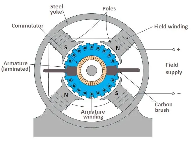
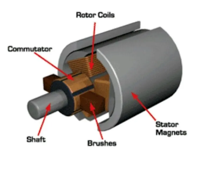
DC Motor construction [2].
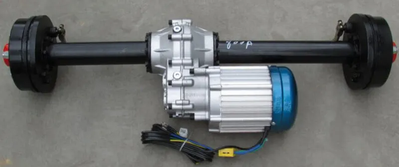
A DC Motor attached to rear axle [3].
To calculate the DC motor speed vs torque characteristics, a Matlab code was written using the formula to calculate the torque generated by the motor by giving manual inputs of supply voltage and constant rotational speed of the motor. The DC motor torque characteristics are calculated using the below formula of rotational speed ω [4]:

When equated to get torque T, we get:
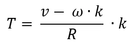
Where,
T = Torque of motor
v = Supply voltage
ω = Rotational Speed
k = Motor Constant
R = Resistance
Hence having the Speed torque linear relation as shown in the figure below:
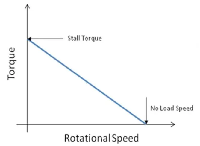
The Matlab code is as shown below.
% DC machine torque speed characteristics

clear all
close all
clc

% Inputs
N = input('Constant Motor Speed Value = ');  % Constant Motor speed input RPM/V
V = input('Voltage = ');    % Supply Voltage input
R = input('Resistance = '); % Armature Resistance input
EMF = 1;    % Back EMF input
n = linspace(0,250,75);     % Motor speed in Rad/sec

% Calculations
% Motor constant
K = ((EMF*60)/(N*2*pi));

% Torque
Torque = ((V*K)/R)-(((K)^2/R)*n);

% Total Current
Current = (V-EMF)/R;

% Max Torque at total current
TMAX = K*Current;

% Converting speed from Rad/sec to RPM
n = n*(9.5541);

% Plotting DC machine characteristics Speed Vs Torque
plot(n,Torque,'color','k','linewidth',3)
xlabel('Speed (RPM)')
ylabel('Torque (Nm)')
title('DC machine characteristics Speed Vs Torque');
grid on
axis([0 2500 0 200])
To start the code the inputs were defined, with manual inputs for the calculation and the motor speed values were defined.
% DC machine torque speed characteristics

clear all
close all
clc

% Inputs
N = input('Constant Motor Speed Value = ');  % Constant Motor speed input RPM/V
V = input('Voltage = ');    % Supply Voltage input
R = input('Resistance = '); % Armature Resistance input
EMF = 1;    % Back EMF input
n = linspace(0,250,75);     % Motor speed in Rad/sec
The inputs given were
Constant Motor Speed value = 100
Voltage= 24
Resistance = 0.017
The variable speed of the motor was defined with linspace function of Matlab between 75 to 250 in rad/sec and the back EMF was kept as 1 as it is proportional to speed and motor speed constant is given in RPM per voltage.
Thereafter the codes for calculations were written, we needed to calculate Motor Constant (K), Torque (T), Total current and Maximum Torque at total current (Tmax). The follow codes are for calculations:
% Calculations
% Motor constant
K = ((EMF*60)/(N*2*pi));

% Torque
Torque = ((V*K)/R)-(((K)^2/R)*n);

% Total Current
Current = (V-EMF)/R;

% Max Torque at total current
TMAX = K*Current;

% Converting speed from Rad/sec to RPM
n = n*(9.5541);
In the end the rotational speed n was converted from rad/sec to RPM for ease of understanding.
Thereafter the graph of Speed VS Torque was plotted. The speed being “n” and the torque “T” which we calculated via Matlab code.
% Plotting DC machine characteristics Speed Vs Torque
plot(n,Torque,'color','k','linewidth',3)
xlabel('Speed (RPM)')
ylabel('Torque (Nm)')
title('DC machine characteristics Speed Vs Torque');
grid on
axis([0 2500 0 200])
The final plot was as seen in the figure below:
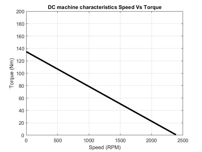
From above shown plot we can say that the speed and torque of a DC machine is inversely proportional to one another.
Part 2: To distinguish between power cables and signal cables in Electric vehicles.
A small fact in automotive electrics and electronics is that the wiring harness in the vehicle is one of the heaviest and most expensive parts of a vehicle after the engine and transmission. In addition, the enormous range of variants of today's vehicle models requires a tailor-made cable system for almost every possible configuration taking in consideration hybrid electric and electric vehicles, even normal cars included having a huge number of electrical operations to run a normal car. Therefore, the cabling is largely manufactured by hand which makes it rather expensive [5].
In electric cars, the wiring harness plays a vital role in passing the electricity to various components installed in the car such as DC motor, 100s of sensors of the electric and mechanical components installed in the vehicle. Power and signal cables are quite similar to each other as they pass electricity to the required sensor or a device to sense or to run a motor or component. The difference between power and signal cable is massive, though both are used as a protection against electricity hazards.
Power Cables: These are basically electrical conductors which are used to transmit a large scale electricity from one point to another. These cables are huge in diameter made of copper and aluminium, where multiple wires are held together for large electric transmissions. A typical power cable can look like the one in figure [6] below.
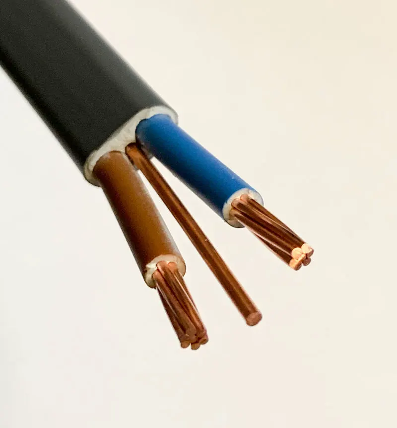
Control Cables: A metal wire or optical fibre that is used to transfer data. Contrast with the "power cable," which provides electricity to any electromechanical device. These cables are low power rated cables sometimes also knows as signal cables. These cables can be used as the signal transmitting cables for sensors. These cables are also used in testing and measurements. Signal cables can also be fibre optic cables to transmit signals to and fro from ECU to sensors. The figure below [7] shows us the different types of sensors connected with signal cable from the ECU.
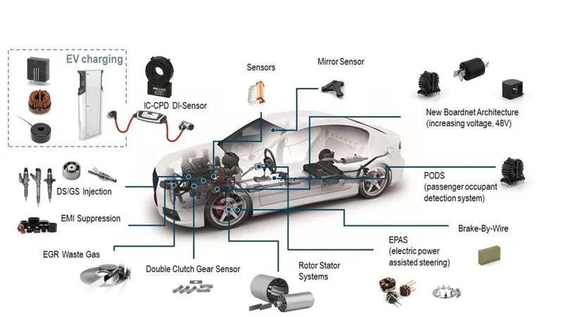
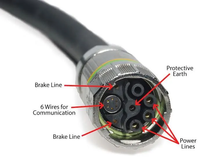
A typical control cable may look like in the figure [8] above:
|
Use/Component |
Cable Type |
|
Vehicle Battery Charging |
Power cable |
|
Battery Connections |
Power cable |
|
Sensor connections |
Control cable |
|
Battery to Motor |
Power cable |
|
Throttle by Wire |
Control cable |
|
Suspension sensor |
Control cable |
Part 3: Study of voltage levels of battery pack of electric vehicles.
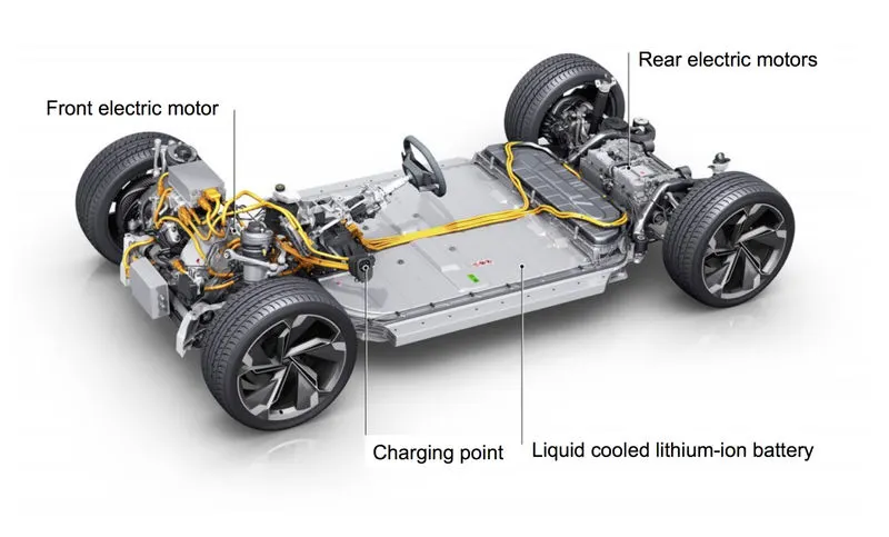
The current generation of electric vehicles uses a very high voltage system due to reduction in appearing current, resulting in a very complex electrical system compared to the normal car. This can be seen as a need of safety of the maintenance staff and the rescue personnel during an accident [9]. A recent accident being an F1 crash involving driver Romain Grosjean where the car was in two pieces after the accident and went into flames. The car is a hybrid electric vehicle having an internal combustion engine and having battery pack to store electricity used in propulsion of the car. The current battery pack of electric and hybrid electric vehicles have operating voltages of 200-800 Volts.
A battery pack of an electric vehicle is mostly composed of several hundred individual cells arranged in series or parallel configuration to achieve desired voltage capacity in the final pack. A common package comprises 18-30 parallel cells. For example, a normal 400V package will involve approximately 96 series blocks. The common packages voltages in existing electric vehicles range from 100V to 200V for hybrid or plug-in hybrid vehicles and 400 to 800V or higher in pure electric vehicles. The reason being higher voltages allow more power to be transferred with less loss over the same diameter of the copper cable. The shortcomings of the higher voltages being the necessity of high voltage rated components in the whole system. They also prevent the ability to use the fast charging DC stations of a lower voltage without incorporating some of the DC-DC boost converters in the on-board charger [10].
The common battery pack ranges are as below:
- Hybrid electric vehicles: 100V to 200V (0.5 to 2 kWh)
- PHEV: 100V to 200V (4 to 20 kWh)
- Pure Electric Vehicles: 400V to 800V (30 to 100 kWh) [10]
A figure [11] showing a full battery pack package installed in a car chassis can be seen below:
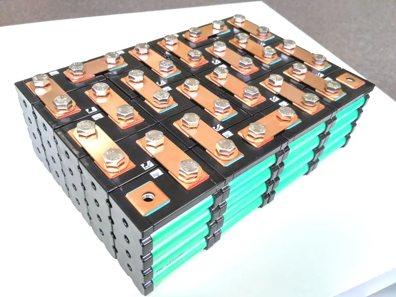
Internal view of cell arrangement in a battery pack [12]:
|
Vehicle |
Battery Pack Capacity |
|
Tesla Model S |
85 kWh |
|
Tesla Model 3 |
82 kWh |
|
Tesla Model X |
75 kWh |
|
Nissan Leaf |
40 kWh |
|
Mercedes EQC |
80 kWh |
|
MG ZS EV |
44.5 kWh |
Concluding the study, we can see different range of battery packs as listed above of high and low capacity of battery packs which are currently in the market.
Conclusions:
- The DC machine torque speed characteristics equations were implemented in Matlab and the Speed VS Torque graph was plotted via Matlab.
- The difference of Power and Signal cable in Electric Vehicle was defined and the use was laid in a tabular form.
- Voltage levels of battery packs in a Electric vehicle was studied and different battery pack capacities were identified.
References:
[1] https://uk.rs-online.com/web/generalDisplay.html?id=ideas-and-advice/dc-motors-guide
[2] DC Motor pic: https://images.app.goo.gl/Z4wk3DwxazPPGdgDA
[3] DC Motor to Axle: https://images.app.goo.gl/iXJ1j7K55rbo4jLd9
[4] https://www.motioncontroltips.com/torque-equation /#:~:text=The%20Torque%20Equation%20and%20the%20Relationship%20with%20DC%20Motors,-March%209%2C%202017&text=And%20when%20supply%20voltage%20is,the%20motor's%20torque%2Dspeed%20curve.
[5] https://www.eenewspower.com/news/how-electric-vehicles-impact-cable-harness-design
[6] https://images.app.goo.gl/vN5jb4tNR2bSHGoh7
[7] https://images.app.goo.gl/bC2CWUnFkUUGHYrTA
[8] Connector: https://www.windpowerengineering.com/single-cable-power-signals-now-servo-drives/
[9[ https://ieeexplore.ieee.org/document/7056185
[10] https://www.allaboutcircuits.com/technical-articles/introduction-to-electric-vehicle-battery-systems/
[11] https://images.app.goo.gl/fTTYA87Sh7dQiYue6
[12] https://images.app.goo.gl/oCMbVnCuQcmZJ2pZ6
Link to Matlab file: https://drive.google.com/file/d/1H9BKXLwyWDJI0MwW4egVsHQiy2M3lOXz/view?usp=sharing