DC Machine Characteristics.
AIM:- To perform DC Machine Characteristics.
Objectives:-
- To write a MATLAB program to Plot the characteristic curve (Speed vs Torque) of the DC motor.
- To distinguish between power cables and signal cables. Also to prepare a table where these cables are used in an electric vehicle.
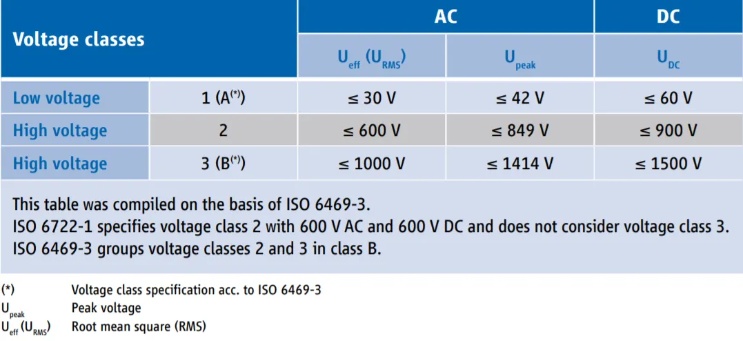
- To study the voltage levels of Electric vehicles.
Introduction:-
The DC machine can be classified into two types namely DC motor as well as DC generator. Most of the DC machines are equivalent to AC machines because they include AC currents as well as AC voltages in them. The output of the DC machine is DC output because they convert AC voltage to DC voltage. The conversion of this mechanism is known as the commutator, thus these machines are also named commutating machines. DC machine is most frequently used for a motor. The main benefits of this machine include torque regulation as well as easy speed. The applications of the DC machine is limited to trains, mills, and mines. For example, subway cars, as well as trolleys, may utilize DC motors. In the past, automobiles were designed with DC dynamos for charging their batteries.
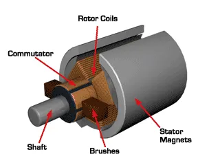
What is DC Machine?
A DC machine is an electromechanical energy alteration device. The working principle of a DC machine is when electric current flows through a coil within a magnetic field, and then the magnetic force generates a torque that rotates the dc motor. The DC machines are classified into two types such as DC generator well as DC motor. The main function of the DC generator is to convert mechanical power to DC electrical power, whereas a DC motor converts DC power to mechanical power. The AC motor is frequently used in industrial applications for altering electrical energy to mechanical energy. However, a DC motor is applicable where good speed regulation & ample range of speeds are necessary like in electric-transaction systems.
what is a DC Motor? The DC motor is the motor that converts the direct current into mechanical work. It works on the principle of Lorentz Law, which states that “the current-carrying conductor placed in a magnetic and electric field experience a force”. And that force is the Lorentz Force.
There are 4 major types of DCmotor and they are,
- Series DC Motor
- Permanent Magnet DC Motor
- Shunt/Parallel DC Motor
- Compound DC Motors
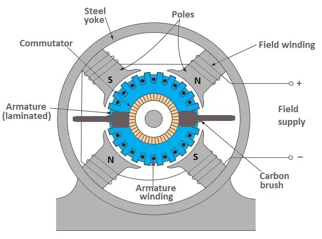
Working Principle of DC Motor - A DC motor is an electrical machine that converts electrical energy into mechanical energy. The basic working principle of the DC motor is that whenever a current-carrying conductor is placed in the magnetic field, it experiences a mechanical force. Fleming’s left-hand rule and its magnitude decide the direction of this force.
Fleming's Left-Hand Rule - If we stretch the first finger, second finger and thumb of our left hand to be perpendicular to each other, and the first finger represents the direction of the magnetic field, the second finger represents the direction of the current, then the thumb represents the direction of the force experienced by the current-carrying conductor.
Back-EMF of DC Motor - According to the fundamental law of nature, no energy conversion is possible until there is something to oppose the conversion. In the case of generators, magnetic drag provides this opposition, but in the case of dc motors, there is back emf. The presence of the back emf makes a dc motor ‘self-regulating’.When the armature of a motor is rotating, the conductors are also cutting the magnetic flux lines and hence according to Faraday's Law of Electromagnetic Induction, an emf induces in the armature conductors. The direction of this induced emf is such that it opposes the armature current (Ia). The circuit diagram below illustrates the direction of the back emf and armature current.
The Different Types of Electric Motors used in Electric Vehicles.
- Brushless DC Motor (PMSM):- This motor has a stator and a rotor with an electric coil in it. When this coil is connected with the battery, producing a direct current, the coil produces a magnetic field which causes the rotor to rotate to have the poles face the opposite poles of the permanent magnets in the stator. To keep this momentum, the polarity of the coils is switched.
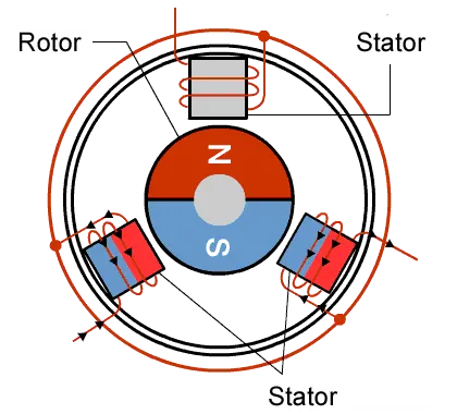
- Induction Motor:- The AC induction motor needs no permanent magnets. Instead, the magnetic field is produced by a current that flows through the windings in the housing or stator. Now if you connect the stator to an alternating current, this means the magnetic field in the stator will also alternate. If a three-phase AC input is used, a so-called rotating magnetic field or RMF is produced. The magnetic field from the stator will induce a voltage and current in the windings of the rotor. That’s why it’s called the induction motor. This in turn leads to the rotor producing its magnetic field, and this magnetic field will make the rotor turn to align itself with the magnetic field from the stator. The rotor will follow this rotating magnetic field in the stator, without the need for a commutator with brushes.
- Synchronous Reluctance Motor:- The synchronous reluctance motor has only recently been developed and seems to have the best of both worlds. It has a rotor that contains metal that is formed in such a way that it wants to align itself naturally to the surrounding magnetic field. This means it doesn’t need to produce its electric field through induced currents, like the induction motor, which means fewer losses. Finally, it doesn’t need permanent magnets which makes it much cheaper than a permanent magnet motor.
Q1.Implement DC machine torque-speed characteristics equations in the MATLAB script file. It asks the user to input data and plots speed (RPM) versus torque (Nm).
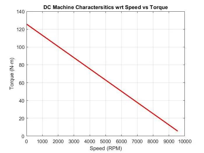
Torque speed behaviours of a DC motor
- When the load on the motor is constant, speed is proportional to supply voltage and when the supply voltage is constant, speed is inversely proportional to the load on the motor.
- The inverse relationship between speed and torque means that an increase in the load (torque) on the motor will cause a decrease in speed.
- This means the torque-speed curve is a descending line, with a negative slope.
- The torque speed curve begins at the crossing of the Y-axis, where torque is maximum and speed is zero. This is the holding torque (maximum torque when the motor is running at nominal voltage).
- The line falls until it intersects the X-axis i.e zero torque and max speed and it is known as no-load speed(the speed when running at nominal voltage and zero loads).
The important characteristics of DC Motor are
- Speed-Armature Current Characteristics
- Torque-Armature Current Characteristics
- Speed-Torque Current Characteristics
The DC machine Torque speed characteristics are plotted by using
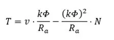
Where,
T = Torque (N-m)
V = Voltage Supply (V)
N = Motor speed(rad/s)
R_a = Armature Resistance(Ohm)
K = Motor Constant
Motor constant value is calculated by using the given equation.
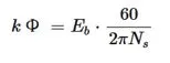
Where,
N_s = Speed constant of the motor
E_b = EMF
MATLAB Code Explanation
- In the MATLAB program, the motor speed is 75 value of the speed range.
- After that specify the input values for motor speed, voltage, and armature resistance value.
- To calculate the motor constant value, enter the formula of motor constant.
- For calculating the torque of the DC machine then enter the torque equation.
- Also, to find the total current we have to enter the equation for that.
- Now enter the plot between speed vs torque
- After that run the code
- After that, we have to enter the values through a command window to plot the graph and for further calculation.
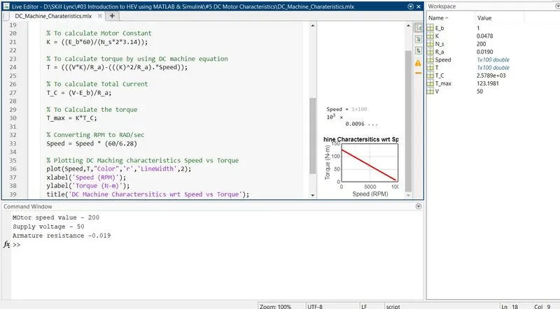
- For these DC characteristics, I used the following values
Motor Speed Value – 200
Supply Voltage - 50
Armature resistance - 0.019
clear all
close all
clc

% Motor Speed in Radian (Rad/sec)
Speed = linspace(1,1000,100);

%constant motor speed (RPM/V)
N_s = input ('MOtor speed value - ');

%Voltage Supply (V)
V = input ('Supply voltage - ')

%Resitance value of Armature (Ohms)
R_a = input ('Armature resistance -');

% Back EMF inputs
E_b = 1;

% To calculate Motor Constant
K = ((E_b*60)/(N_s*2*3.14));

% To calculate torque by using DC machine equation
T = (((V*K)/R_a)-(((K)^2/R_a).*Speed));

% To calculate Total Current
T_C = (V-E_b)/R_a;

% To Calculate the torque
T_max = K*T_C;

% Converting RPM to RAD/sec
Speed = Speed * (60/6.28)

% Plotting DC Maching characteristics Speed vs Torque
plot(Speed,T,"Color",'r','LineWidth',2);
xlabel('Speed (RPM)');
ylabel('Torque (N-m)');
title('DC Machine Charactersitics wrt Speed vs Torque');
grid on
Output:-
Graph:-
Q2. How can you distinguish between power cables and signal cables and also prepare a table where these cables are used in the wiring of an electric vehicle?
What is a cable?
Like a pipe that carries water to your home, or waste from it, the role of cable is to carry an audio or video signal from one device to another. Cables carry signals between DVD players and TVs, stereo receiver's and speakers, and computers and video projectors. Cables are messengers that don't process the signals provided to them
What does a cable consist of?
Cables are made up of 3 basic parts- conductor, shielding and connector. The conductor is the wire that carries the signal. One or more layers of shielding prevent the wire from acting as an antenna that picks up the radio frequency interference and electromagnetic interference. The connector is the plug at the end of the cable that connects to your device.
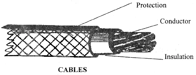
A car's wiring has to distribute power from the battery to devices located all over the car. It also has to transmit data on a data bus, as well as a variety of digital and analogue signals from switches and sensors. This means that there are many different types of wires in your car. Some wires that transmit signals from switches or sensors carry almost no current. Those that provide power to large electric motors carry lots of currents. If too much current goes through a wire, it can overheat and melt. The amount of current that a wire can handle depends on its length, composition, size and how it is bundled
- Length - Each type of wire has a certain amount of resistance per foot -- the longer the wire, the larger the resistance. If the resistance is too high, a lot of the power that flows down the wire will be wasted; the energy is lost as heat builds up in the wire. Ultimately, heat build-up limits the current-carrying capacity of the wire, as the temperature must not get hot enough to melt the insulation.
- Composition - Automotive wire is usually composed of fine copper strands. Generally, the finer the strands, the lower the resistance and the more current the wire can carry. The type of copper used affects the resistance of the wire, too.
- Wire gauge - The wire gauge, or size of the wire, also determines how much resistance the wire has. The larger the wire, the less resistance. The smaller the gauge, the larger the wire -- so a 16-gauge wire is bigger than a 24-gauge wire. Wire gauges go all the way down to zero, which is also called 1/0 (one aught). Even bigger than 1/0 is 00 (2/0, or two aught), and so on. The diameter of a 4/0 (four aught) wire is almost half an inch (1.27 cm).
- Bundling - The way a wire is bundled affects how well it can dissipate heat. If the wire is in a bundle with 50 other wires, it can carry a lot less current than if it were the only wire in the bundle
Signal Cable:-
Signal cable is used in data transmission applications that demand superior signal protection. These applications require some of the smallest, most flexible, and highly-screened cables on the market. Signal cables are used in a multitude of industries and can be found in everything from computers, medical equipment, and appliances.
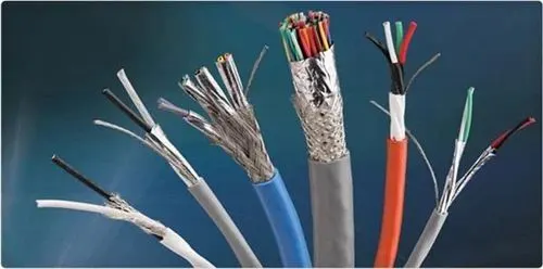
Signal cables are low power and currently rated wires whereas power cable is high current rated and power. Signal cables will be smaller gauges and consist of multiple individually shielded twisted pairs. Signal cables are not a heavy enough gauge to prevent too much voltage drop or actual cable overheating and damage when used in a control circuit. Control circuits could easily be 1 to 5 amps.
Power Cable:-
Power Cables are electrical conductors that are held together to transmit electric power on a large scale. It has many industrial applications that make the wires a popular choice to be used in ships, airports, industrial areas, underground, hospitals, commercial centres, and many more. When they are installed, they can be either exposed or buried deep within the ground or a building. There are different sorts of power cables such as flexible cables which can also be used for mobile tools as well as heavy machinery.
| SIGNAL CABLE | POWER CABLE |
|
|
|
|
|
|
|
|
|
|
|
|
|
|
|
|
Wiring of Electric Vehicles
Electric vehicle wiring is similar to battery cables in conventional vehicles, except that EV cables are shielded. The shield is typically foil covered by a tinned-copper braided shield. The shielding is required to reduce electromagnetic and radio frequency interference (EMI/RFI) caused by the electrical noise generated by the high-frequency switching that takes place in the inverter.
In traditional vehicles, the most cost-effective method of suppressing EMI/RFI noise is through the use of components such as capacitors, inductors and diodes. But, shielding electronics and wiring becomes a more cost-effective solution in HEV's because the traditional suppression components required would be too large and heavy to be practical. Hence this brings us to the need of having perfect wiring, to make the manufacturing productive.
Application of Cables in EV
SIGNAL CABLES
- Automotive Battery cables
- Sensor Cables
- ABS (Anti-lock Braking System)
- EPB (Electronic Parking Brake)
- EPS (Electronic Power Steering)
- DCT (Dual-Clutch Transmission) - Camera Sensor
- Around View Monitor camera
- Front camera
- Rear camera - Car Audio Speaker
- Car Dashboard etc...
POWER CABLES
- Engine Bay
- Controls
- Actuators
- Switches etc... - Battery
- Lighting
- Car interior main cable
- Car sunroof
- Car Doors
- Power Transmission etc...
Q3.What voltage levels are considered as high & low for a battery pack of an electric vehicle?
A figure showing a full battery pack installed in a car Chassis can be seen below;
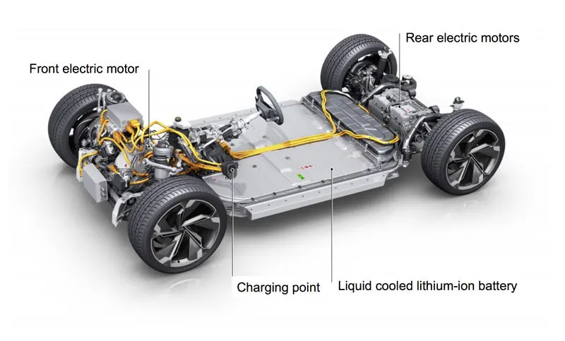
An electric vehicle battery is often composed of many hundreds of small, individual cells arranged in a series/parallel configuration to achieve the desired voltage and capacity in the final pack. A common pack is composed of blocks of 18-30 parallel cells in series to achieve the desired voltage. For example, a 400V nominal pack will often have around 96 series blocks (as in the Tesla Model 3).
Common nominal pack voltages in current vehicles range from 100V-200V for hybrid/plug-in hybrid vehicles and 400V to 800V and higher for electric-only vehicles. The reason for this is higher voltages allow more power to be transferred with less loss over the same diameter (and mass) of copper cable. A battery pack of an electric vehicle is mostly composed of several hundred individual cells arranged in series or parallel configuration to achieve desired voltage capacity in the final pack. A common package comprises 18-30 parallel cells. For example, a normal 400V package will involve approximately 96 series blocks. The common packages voltages in existing electric vehicles range from 100V to 200V for hybrid or plug-in hybrid vehicles and 400 to 800V or higher in pure electric vehicles. The reason being higher voltages allow more power to be transferred with less loss over the same diameter of the copper cable. The shortcomings of the higher voltages are the necessity of high voltage rated components in the whole system. They also prevent the ability to use the fast charging DC stations of a lower voltage without incorporating some of the DC-DC boost converters in the onboard charger.
Common battery capacity ranges;
| Hybrid Vehicles (HEV) | 100V to 200V | (0.5kWh to 2kWh) |
| Plug-in Hybrid vehicle (PHEV) | 100V to 200V | (4kWh to 20kWh) |
| Electric vehicle (EV) | 400V to 800V | (30kWh to 100kWh) |
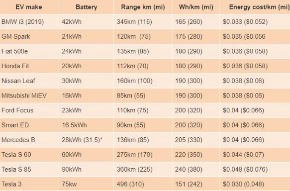
Estimated energy consumption and cost per Km/mile of common EVs.
References:-
- https://www.motioncontroltips.com/torque-equation/#:~:text=DC%20motors%20are%20relatively%20simple,the%20load%20on%20the%20motor.&text=Therefore%2C%20when%20supply%20voltage%20(V,proportional%20to%20speed%20(%CF%89)
- https://www.allaboutcircuits.com/technical-articles/introduction-to-electric-vehicle-battery-systems/#:~:text=Common%20nominal%20pack%20voltages%20in,and%20mass)%20of%20copper%20cable.
- https://m.zmscable.com/new/What-is-the-difference-of-control-cable-and-power-cable
- https://www.zvei.org/fileadmin/user_upload/Presse_und_Medien/Publikationen/2014/april/Voltage_Classes_for_Electric_Mobility/Voltage_Classes_for_Electric_Mobility.pdf
- https://www.emobility-engineering.com/high-voltage-cables/
- https://www.slideshare.net/vguardindustries/the-main-differences-between-power-and-control-cables-a-primer-24376868