Cyclone Separator Challenge
Problem Statement:
1. Perform the analysis on the cyclone separator model by varying the particle size with a constant inlet velocity of 3m/s for particle and continuous phase velocity.
2. Perform the analysis on cyclone separator model by varying the inlet velocity of particle and continuous phase with a constant particle size of 5`mu`m
Introduction:
Cyclone Separator:
A cyclone separator is a device that uses centrifugal forces to separate the solids from the carrier gas. This is widely used in industry at the initial stage of the cleaning process as it has a low capital cost and maintenance cost.
Parts of Cyclone Separator
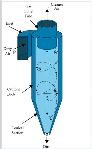
Working Principle of Cyclone Separator:
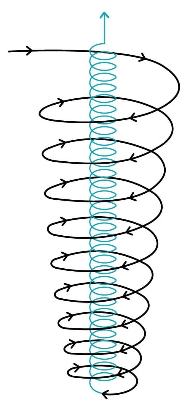
Gas containing entrained particles enters at high velocity through the tangential inlet at the top of the cyclone. The gas flows into the cyclone body at a tangent and begins to flow in a circular downward spiral towards the lower reject port, this downward flowing spiral is referred to as a spiral vortex.
The cone diameter gradually decreases which causes the gas velocity to increase. The outer vortex creates an additional inner vortex closer to the center of the separator body and this inner vortex flows spirally upwards towards the accept port.
Particles with more inertia will impact the side of the cyclone whilst particles with lower inertia will remain within the gas stream. Inertia can be thought of as a particle’s ability to continue traveling in a straight line even when external forces are applied. When an external force is applied -such as by the cyclonic vortex- the particles with low inertia will not continue to travel in a straight line, they will instead travel spirally as they are swept along by the gas stream.
Particles with greater inertia will be less affected by the vortex and will continue traveling in a straight line. This straight-line trajectory causes the high inertia particles to move out of the gas stream and impact the cyclone separator body. These particles then fall to the base of the cyclone separator and out of the reject port. In this way, entrained particles of a certain size can be separated from the gas stream.
Applications of Cyclone Separator:
In general, cyclones are used to collect particles greater than 10 micrometers in diameter and are sometimes referred to as "pre-cleaners", because they are often used to reduce the inlet loading of particulate matter to downstream collection devices by removing larger, abrasive particles. However, a high efficiency cyclone can be employed to collect smaller particles, which requires a higher pressure drop and energy costs.
Some of them are:
1. oil refineries to separate oils and gases
2. cement industry
3. vacuum cleaners
Discrete Phase Modelling (DPM)
The lagrangian discrete model in ANSYS FLUENT flows the Euler-Lagrange approach. The fluid phase is treated as a continuum by solving the Navior-Strokes Equations, while the dispersed phase is solved by tracking a large number of particles, bubbles, or droplets through the calculated flow field. The dispersed phase can exchange momentum, mass, and energy with the fluid phase.
A fundamental assumption made in this model is that the dispersed second phase occupies a low volume fraction. The particle or droplet trajectories are computed individually at specified intervals during the fluid phase calculations.
ANSYS FLUENT predicts the trajectory of a discrete phase particle by integrating the force balance on the particle, which is written in a Lagrangian reference frame.
Cyclone Separator Models:
Barth model:
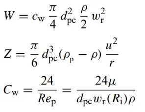
Barth proposed a simple model based on force balance. This model enables to obtain the cut-size (the diameter of the particle for which efficiency cure is 50%) and the pressure drop values. The principle of calculation consists of the fact that a particle carried by the vortex endures the influence of two forces: a centrifugal force Z and a flow resistance W. They are expressed at the outlet radius `R_i` where the highest tangential velocity occurs:
The tangential velocity at `R_i` equals:
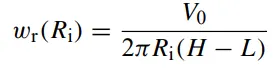
The radial velocity u(`R_i`) equals:
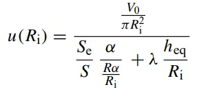
where
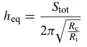
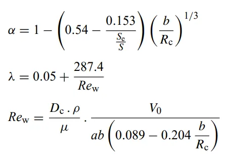
`alpha` is a correction factor for contraction, expressed as a function of the inlet geometry and `lamda` a friction factor either equals to 0.02 or a function of the inlet geometry and the inlet flow rate described by Muschelknautz and Brunner
The pressure drop is resolved into two terms. The first term reflects the contribution by inlet losses and friction losses. The second term results from the flow losses through the outlet pipe.
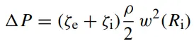
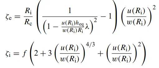
This model is relatively simple but it allows to obtain easily an approximation of the pressure drop and cut diameter which are the two main parameters for an industrial approach.
Lozia and Leith Model:
Lozia and Leith's logistic model is a modified version of the Barth model which is developed based on force balance. The model assumes that particles carried by the vortex endure the influence of two forces, centrifugal forces and a flow resistance W. The collection efficiency `eta_i` of particle diameter `d_("pi")` can be calculated from
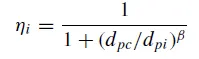
where `beta` is an expression for slope parameter derived based on the statistical analysis of experimental data of a cyclone with D=0.25m given as

`d_(pc)` is the 50% cut size given by Barth
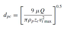
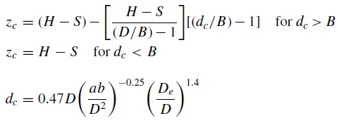
whose core length, `z_c` and core diameter `d_c` are given as
Li and Wang Model:
The Li and Wand model includes particle bounce or re-entrainment and turbulent diffusion at the cyclone wall. A two-dimensional analytical expression of particle distribution in the cyclone is obtained. Li and Wang's model was developed based on the following assumptions:
1. The radial particle velocity and the radial concentration profile are not constant for uncollected particles within the cyclone.
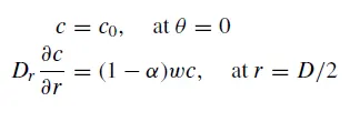
2. Boundary conditions with the consideration of turbulent diffusion coefficient and particle bounce re-entrainment on the cyclone wall are:
3. The tangential velocity is related to the radius of cyclone by: u`R^n` = constant.
The concentration distribution in a cyclone is given as:
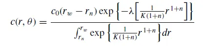
where
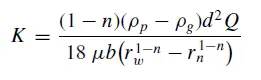
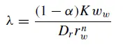
The resultant expression of the collection efficiency for particle of any size is given as
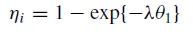
where

Lapple Model:
Lapple model was developed based on force balance without considering the flow resistance. Lapple assumed that a particle entering the cyclone is evenly distributed across the inlet opening. The particle that travels from inlet half-width to the wall in the cyclone is collected with 50% efficiency. The semi-empirical relationship developed by Lapple to calculate a 50% cut diameter, `d_pc` is
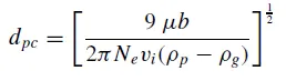
where `N_e` is the number of revolutions
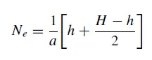
The efficiency of collection of any size of the particle is given by
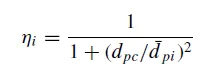
Dimensions of the cyclone separator:
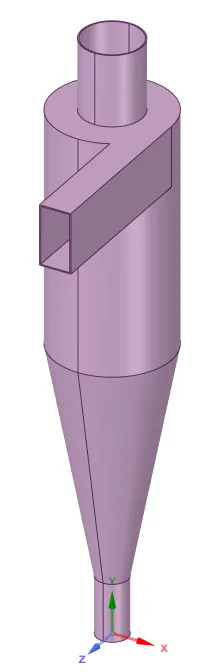
Geometry:
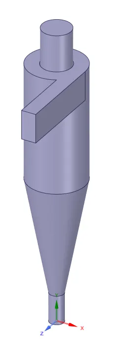
Volume extracted:
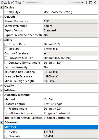
Mesh Parameters:
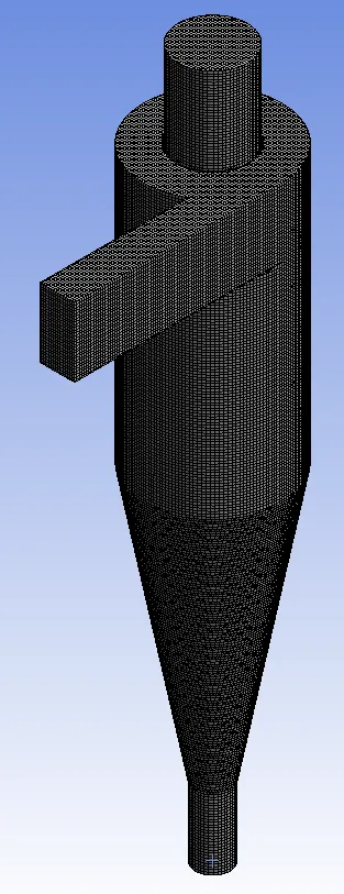
Meshed model:
Mesh quality:
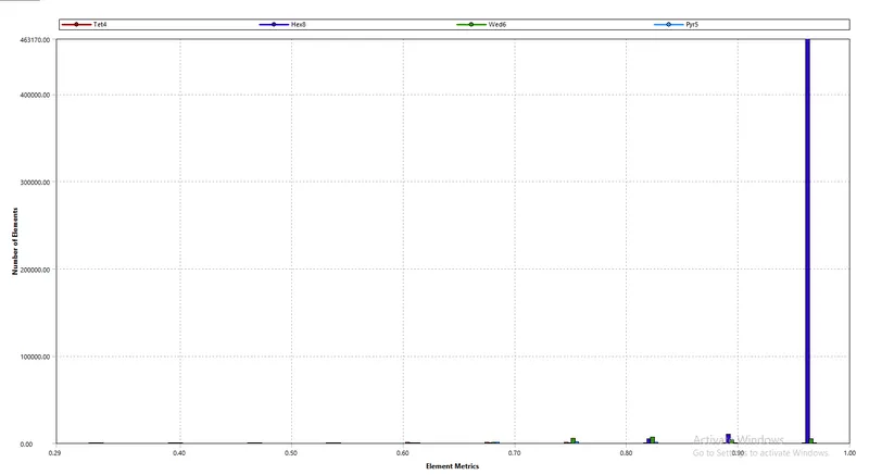
With the use of the Cutcell method of meshing an acceptable mesh quality is obtained. The cut cell method helps in the generation of structured mesh for the given component with a max element size of 6.9mm.
Setting Up physics:
1. Pressure based steady-state solver is used with gravity acting in the negative y-direction. As the Mach number for the flow is less than 0.3 pressure-based solver is used.
2. K-epsilon RNG turbulence model with swirl dominated flow is used for the analysis of the cyclone separator. This turbulence model enhances the accuracy of the swirl dominated flow.
3. Discrete phase model is defined with coupled interaction with the continuous phase. Tracking parameters and update of the iterations are set to default values provided by the Ansys. Here step length factor=5 is used to control the size of the time step. Larger the factor, smaller the time step will be and also tracking parameters calculates the trajectory parameters of the particles for the number of time steps provided.
4. The particles are defined in the injection menu under discrete phase where the particle material is anthracite which is also known as hard coal. Injection type is surface, here the inlet surface has to be specified as the cyclone separator has 1 inlet. The distribution of the particles is uniform with velocity and diameter specified in accordance with the case performed.
5. Boundary conditions are defined in which the inlet velocity of the fluid is taken to be the same as the particle velocity and in the discrete particle model reflect boundary condition is defined for the inlet.
For outlet1 that is for the upper outlet escape boundary condition and bottom outlet trap, the boundary condition is defined.
The explanation for boundary conditions defined for the inlet and outlet:
Reflect: This boundary condition is defined when a particle rebounds off the wall with a change in momentum.
Trap: The trajectory calculations are terminated and the fate of the particle is recorded as trapped.
Escape: When the particle encounters the outlet boundary it is treated as escaped and terminates the trajectory calculations.
Wall-jet: The wall-jet type boundary condition is appropriate for high-temperature walls where no liquid film is formed.
Wall-film: This boundary condition consists of four regimes: stick, rebound, spread, and splash, which are based on the impact of energy and wall temperature.
6. Initialization is done using the standard settings with second-order accuracy of the solution controls. Higher-order solution methods are used to achieve greater accuracy in the results.
7. The simulation is run for 500 iterations even though residuals converge at the 150th iteration.
Results:
Residual Plot:
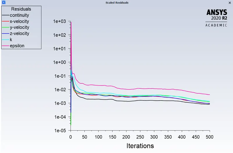
From the residual plot, we can infer that the solutions are converged.
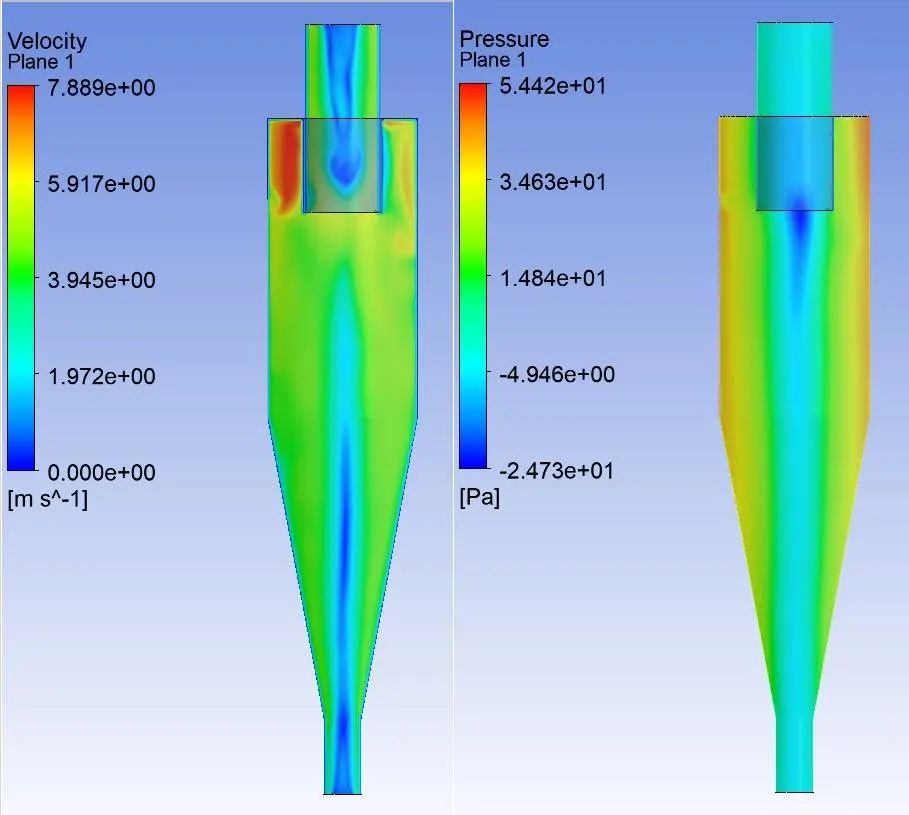
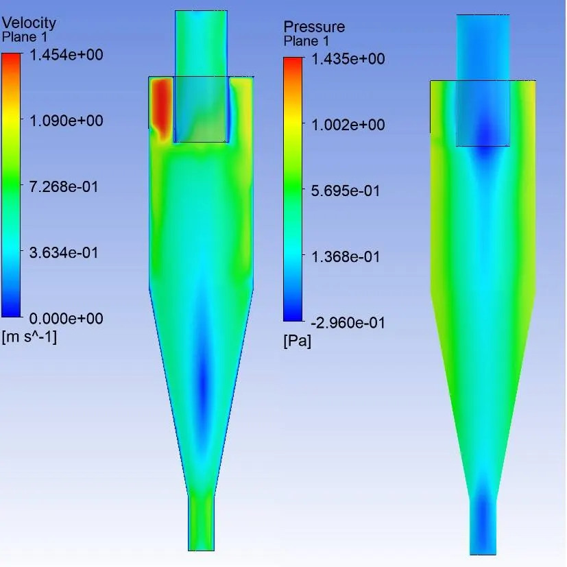
Velocity and pressure plot for 5m/s.
Velocity and pressure plot for 3m/s.
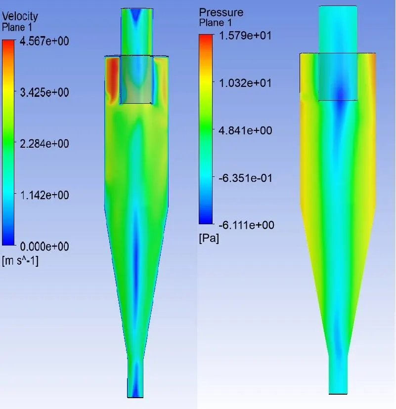
Velocity and pressure plot for 1m/s.
Inference:
From the above pressure velocity plots, we can infer that the pressure is higher near the wall region which forms the outer vortex. Due to higher pressure near the wall low-pressure region is created at the center of the cyclone separator because of which the lighter particles escape from the top outlet and heavier particles are collected at the bottom outlet.
Video depicting the flow of particles of size varying from 1`mu`m to 5`mu`m with a constant velocity of 3m/s.
In the above video, simulation is done for particle size varying from 1`mu`m to 5`mu`m with air and particle velocity as 3m/s. From the video, it is observed that heavier particle is trapped at the bottom outlet and lighter particles are escaped at the outlet 1. But we can also see that lighter particles also get trapped at the bottom outlet because of interaction between lighter and heavier particles and there is an exchange of inertial forces between them as a result there is a transfer of Kinetic energy from heavier particle to the lighter particle, as a result, we can observe a certain number of heavier particles escapes through the top outlet.
Video showing the flow of particles of size 5`mu`m with 1m/s as inlet velocity.
Video showing the flow of particles of size 5`mu`m with 3m/s as inlet velocity.
Video showing the flow of particles of size 5`mu`m with 5m/s as inlet velocity.
Efficiency Formula(`eta`):
`eta = "No. of particles trapped"/("No. of particles injected"-"No. of particles incomplete")`
| Case No. | Case Type | No. of Particles Tracked | Escaped | Trapped | Incomplete | Efficiency in % | Pressure Drop between inlet and outlet in Pa |
|
1 |
Particle Size = 1`mu`m Velocity = 3m/s |
435 | 222 | 192 | 21 | 46.3 | 9.59 |
|
2 |
Particle Size = 3`mu`m Velocity = 3m/s |
435 | 183 | 233 | 19 | 56.3 | |
|
3 |
Particle Size = 5`mu`m Velocity = 3m/s |
435 | 88 | 326 | 21 | 78.7 | |
|
4 |
Velocity = 1m/s Particle Size = 5`mu`m |
435 | 170 | 83 | 182 | 32.8 | 1.14 |
|
5 |
Velocity = 3m/s Particle Size = 5`mu`m |
435 | 93 | 285 | 57 | 75.3 | 9.68 |
|
6 |
Velocity = 5m/s Particle Size = 5`mu`m |
435 | 12 | 423 | 0 | 97.2 | 29.69 |
Inference:
The collection efficiency of cyclones varies as a function of particle size, density, and cyclone design. Cyclone efficiency will generally increase with the increase in particle size, density, inlet duct velocity, cyclone body length, number of gas revolutions in the cyclone, the ratio of cyclone body diameter to gas exit diameter, inlet dust loading, smoothness of the cyclone inner wall.
The efficiency of the cyclone will decrease with an increase in the parameters such as gas viscosity, cyclone body diameter, gas exit diameter, gas inlet duct area, gas density, leakage of air into dust outlet.
With the increase in inlet velocity or particle size the efficiency increases.
The collection efficiency of the cyclone separator is related to the pressure drop across the cyclone. Here pressure drop is the indirect measure of the energy required for the gas to move the particles. Pressure drop is related to the inlet velocity of air and particle size.
Pressure drop occurs because of the following components:
1. Loss due to the expansion of gas in the cyclone chamber.
2. Loss due to rotational kinetic energy.
3. Loss due to wall frictional forces