Cyclone Separator
Cyclone Separator and its efficiency
1.0 Introduction
A cyclone separator is a low cost device used by industries to separate out small particles present in a gas carrier. The principle involves the use of centrifugal force generated by the carrier as it passes through the separator to separate out the particles. Dirty flue gases (carrier) are fed into the inlet of the separator into a spiral vortex. Lighter particles move to the top whereas heavier particles collide with the walls and settle to the bottom. (Dustbin). The efficiency of the cyclone separator is usually at the highest (99%) for particles that are greater than sizes of 5 μm.
The common reason for use of cyclone seperator is due to the low cost, geometric simplicity and wide range of application flexibility. Engineers use CFD to predict the seperation efficiency of a cyclone and pressure drop in the cyclone.
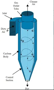
In this study, firstly some common emperical models used to calculate efficiency will be discussed. Next, Ansys fluent will be used to simulate a cyclone seperator's functioning. After performing a geometry clean up in spaceclaim followed by meshing, various parametets will be studied and compared in fluent and CFD post.
2.0 Objectives
- To discuss four empirical models used to calculate cyclone efficiency.
- To compare the separation efficiency of a cyclone separator model for particle sizes varying from 1 to 5 μm, at a velocity of 3 m/s.
- To compare the separation efficiency of a cyclone separator model for a velocities varying from 1 to 5 m/s, at a particle size of 5 μm.
3.0 Cyclone efficiency empirical models
3.1 Iozia and Leith Model
This model is a modified version of the Barth model that is based on force balance.
According to this model, a particle is influenced by 2 forces when it is inside the vortex, a centrifugal force Z and a flow resistance W.
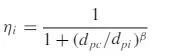
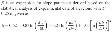
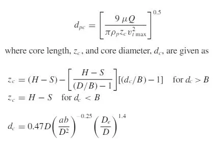
The collection efficiency ηi of particle diameter dpi can be calculated from
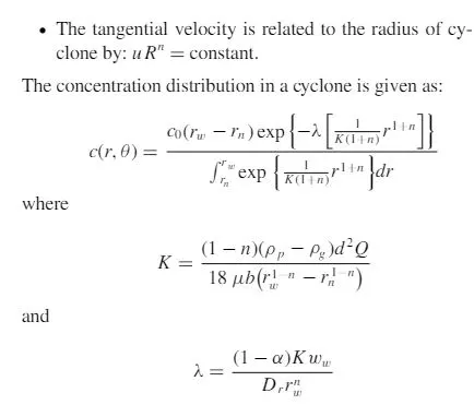
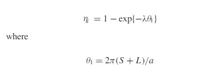
3.2 Li and Wang model
This model includes particle bounce or re-entrainment and turbulent diffusion at the cyclone wall.
Assumptions:
- The radial particle velocity and the radial concentration profile are not constant for uncollected particles within the cyclone
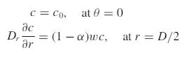
- Boundary conditions with the consideration of turbulent diffusion coefficient and particle bounce re-entrainment on the cyclone wall are:
3.3 Koch and Licht Model
This model recognized the inherently turbulent nature of cyclones and the distribution of gas residence times within the cyclones.
Assumptions:
- The tangential velocity of a particle is equal to the tangential velocity of the gas flow, i.e. there is no slip in the tangential direction between the particle and the gas.
- The tangential velocity is related to the radius of cyclone by: uRn= constant.
A force balance and an equation on the particles collection yields the grade efficiency ηi:
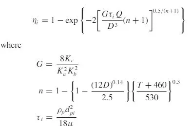
G is a factor related to the configuration of the cyclone, n is related to the vortex and τ is the relaxation term.
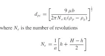
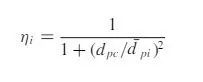
3.4 Lapple Model
This model considered force balance while neglecting flow resistance.
Assumptions:
A particle entering the inlet is evenly distributed across the opening. The particle that travels from inlet half width to the wall in the cyclone is collected with 50% efficiency.
4.0 Methodology
4.1 Modelling Approach
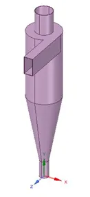
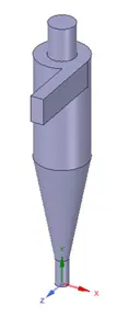
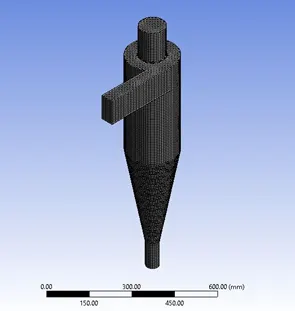
Using spaceclaim, a fluid volume was extracted from a cyclone separator model.
4.2 Mesh Approach
Mesh details:
|
Element size (Using body sizing) |
10 mm |
|
Number of Nodes |
66722 |
|
Number of Elements |
64227 |
CutCell method was enabled to obtain a structured mesh.
Named selections were created for inlet, outlet at the top, and outlet at the bottom.
The wall area is not selected as fluent automatically assumes the remaining region as a fluid wall.
5.0 Processing Approach
Discrete Phase Modelling is turned on. This is done so that the fluid continuum is solved using the Navier-Stokes equations, whereas the particles are tracked individually by studying their motion through the flow medium (Lagrangian Approach).
|
Turbulence Model |
K epsilon RNG, Swirl Dominated Flow (To account for the swirl motion of the fluid) |
|
Solver |
Pressure based |
|
Time |
Steady |
|
Gravity |
-9.81 m/s2, Y direction |
Discrete phase modelling details
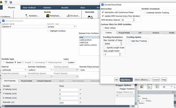
Note: Diameter and Velocity will be changed each time; the above figure is just an example of turning on the discrete phase model.
Boundary conditions
|
Inlet |
Reflect |
|
Outlet top |
Escape |
|
Outlet bottom |
Trap |
|
Wall |
Reflect |
Solution Method
|
Turbulent Kinetic Energy |
Second order Upwind |
|
Turbulent Dissipation Rate |
Second order Upwind |
Second order upwind is more accurate for discretization problems.
Solution Initialization: Standard
Compute from Inlet
Seperation Efficiency = Number of Particles Trapped / Number of Particles Tracked
5.1 Separation Efficiency by varying the particle diameter from 1 to 5 μm, constant velocity of 3 m/s
5.1.1 Case 1
Particle Diameter = 1 μm
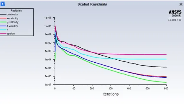

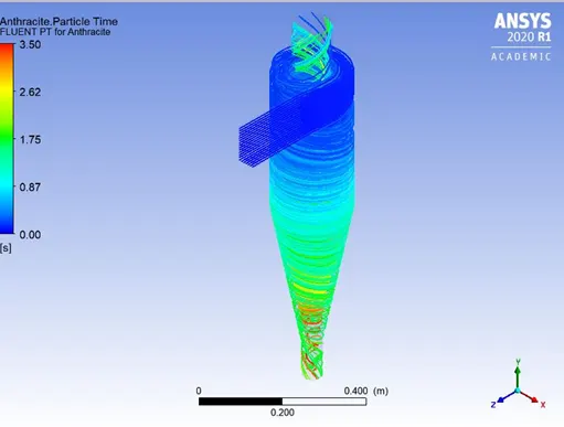
Separation Efficiency = 34/98 = 35%
5.1.2 Case 2
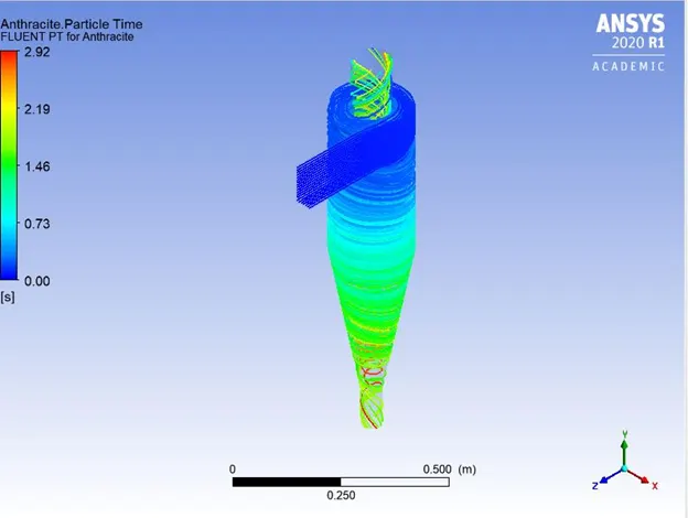
Particle Diameter = 2 μm
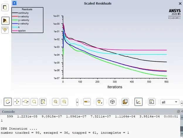
Separation Efficiency = 61/98 = 62.24%
5.1.3 Case 3
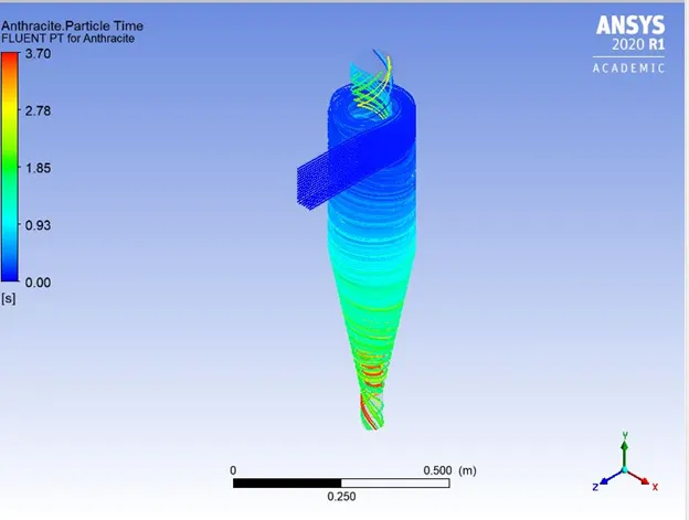
Particle Diameter = 3 μm
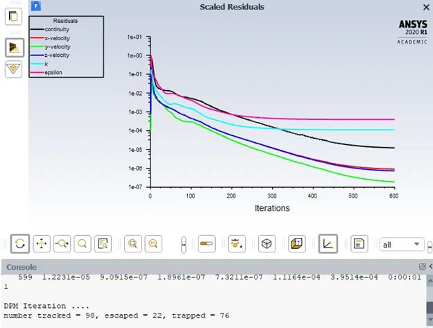
Separation efficiency = 76/98 = 77.5%
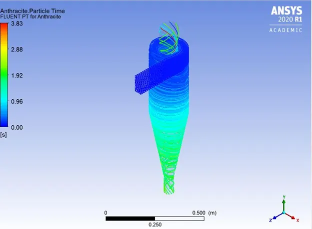
5.1.4 Case 4
Particle Diameter = 4 μm
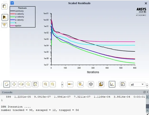
Separation efficiency = 86/98 =87.75%
5.1.5 Case 5
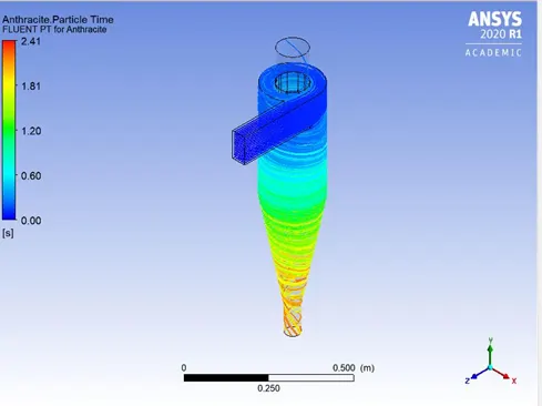
Particle Diameter = 5 μm
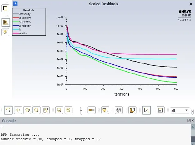
Separation Efficiency = 97/98 = 99%
5.2 Comparison and study of pressure drop and separation efficiency for velocities from 1-5 m/s, keeping the particle size constant (5 μm)
5.2.1 Case 1
Velocity = 1 m/s
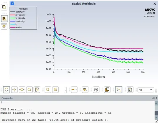
Separation efficiency = 8/98 = 8.16 %
Very poor efficiency is observed.
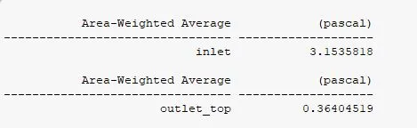
Pressure drop = Inlet – Outlet = 3.153 – 0.364 = 2.789
5.2.2 Case 2
Velocity = 2 m/s
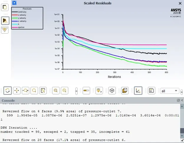
Separation efficiency = 35/98 = 36%
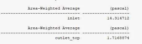
Pressure drop = 14.314 – 1.716 = 12.598
5.2.3 Case 3
Velocity = 3 m/s
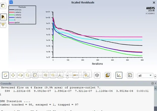
Separation Efficiency = 99%
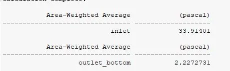
Pressure drop = 31.687
5.2.4 Case 4
Velocity = 4 m/s
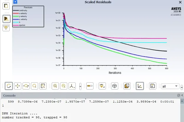
Separation efficiency = 100%
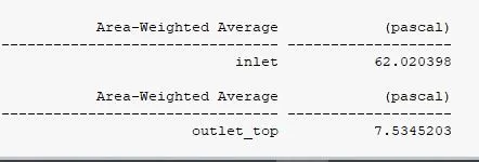
Pressure drop = 54.486
5.2.5 Case 5
Velocity = 5 m/s
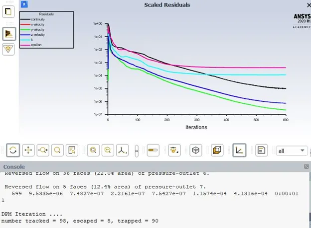
Separation efficiency = 90/98 = 92%
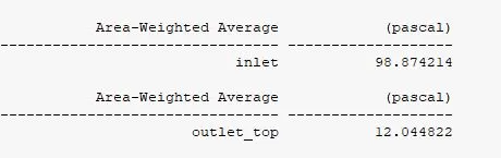
Pressure drop = 86.83
6.0 Results
|
Particle size in μm |
Separation Efficiency in Percentage |
|
1 |
35 |
|
2 |
62.24 |
|
3 |
77.55 |
|
4 |
87.77 |
|
5 |
99 |
|
Inlet Velocity in m/s |
Pressure drop in Pa |
Separation Efficiency in Percentage |
|
1 |
2.78 |
8.16 |
|
2 |
12.59 |
36 |
|
3 |
31.68 |
99 |
|
4 |
54.48 |
100 |
|
5 |
86.83 |
92 |
7.0 Inferences
- The ideal particle size would be 5 μm or greater. Values below that would lead to the cyclone separator having lower efficiencies.
- As the inlet velocity increases for a 5 μm diameter particle, the separation efficiency increases. However, at a velocity of 5 m/s, it decreases. This is due to more number of particles exiting from the top of the cyclone separator compared to the other inlet velocities.
- With an increase in inlet velocity, there is a greater pressure drop during the flow from the inlet to outlet.
8.0 References
- Numerical study of gas-solid flow in a cyclone separator
- A CFD Study on the Prediction of Cyclone Collection Efficiency