Creation of Multiple viewports, Scaling the drawing and setting in Template in AutoCad
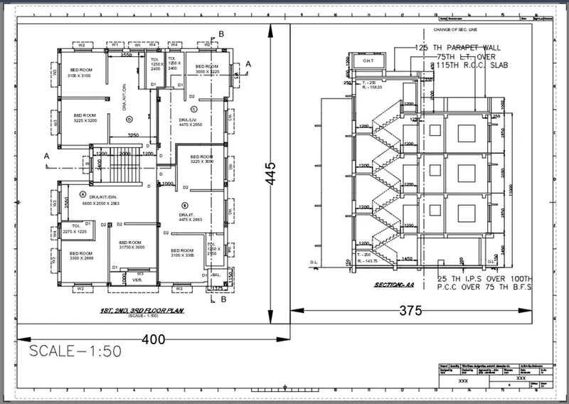
Create a layout of the Plan and Section A of the project in Challenges 7, using the template Tutorial-mArch.dwt in a scale as given in the Figure. Use the MV command to create the viewport of the size as shown in Figure. Also, use ATTEDIT command to edit the information in the title block. Use A1 size for the layout. Take a plot.
AIM:
To create a layout of the plan and section of the project by using the tools from AutoCAD.
INTRODUCTION:
Layout:
Display one or more scaled views of design on a standard size drawing sheet called a layout. After finish of creating a model at full size, it can be switch to a paper space layout to create scaled views of the model, and to add notes, labels, and dimensions.
PROCEDURE:
step – 1:
- To create a layout, firstly we have to complete the sketch of the project.
- After complete the sketch of the project, we have to save the drawings by using the command NEWVIEW for easy to create the layouts.
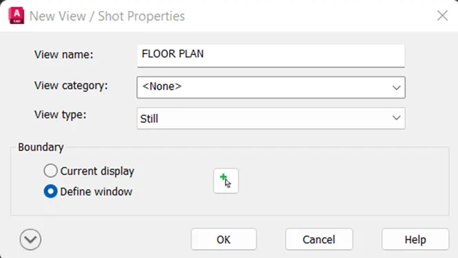
- Firstly, we have to save the floor plan of the sketch by using the command NEWVIEW.
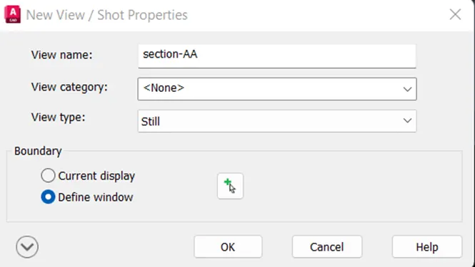
- By using the same command save the section-AA also.
Step -2:
- Select the command LAYOUT to create a new layout.
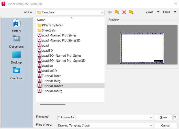
- Select the command TEMPLATE to create a new template, there are some fixed templates in AutoCAD.
- Select the template Tutorial-mArch to create a new template.
- After completing the selection of template now we have to select the sheet size or paper size.
- Use the option Page Setup and select the paper size to A1
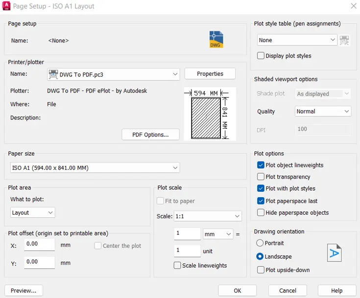
- After completion of paper size and selection of template the layout sheet is looks like this.
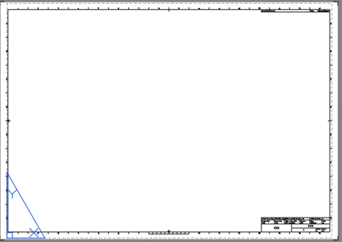
Step – 3:
- After completing the template, now we have to create required viewports.
- Select the command MVIEW and select the option named, because we have already saved the required viewports.
- By using the command MVIEW create floor plan viewport and place it on specified place.
- We can also adject the viewport by using the command MS and to adject the paper by using the command PS.
- After completing the placement of viewport, we have to lock the viewport by using the command MVIEW.
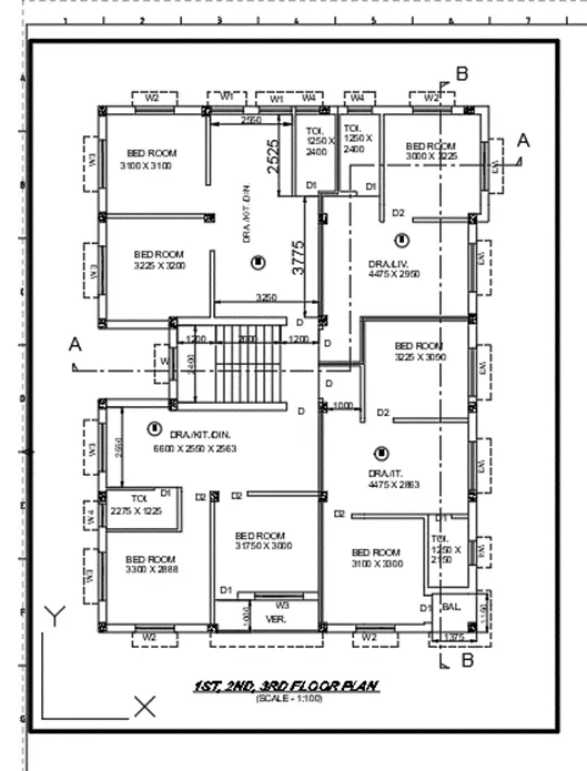
- After completion of floor viewport, now we have to create a new viewport for section-AA by using the command MVIEW.
- Adject the viewport by using the command MS and to adject the paper by using the command PS.
- After completing the placement of viewport, we have to lock the viewport by using the command MVIEW.
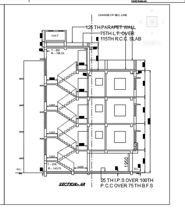
- After completing the layout, we have text the layout at specified places by using the command DTEXT.
- Also give the dimensions for layout at specified places by using the command DIMLIN.
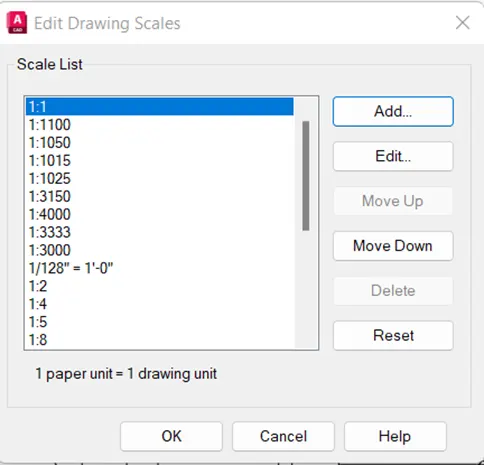
- Adject the drawings in the viewports in perfect size by using the command SCALE.
Step – 4:
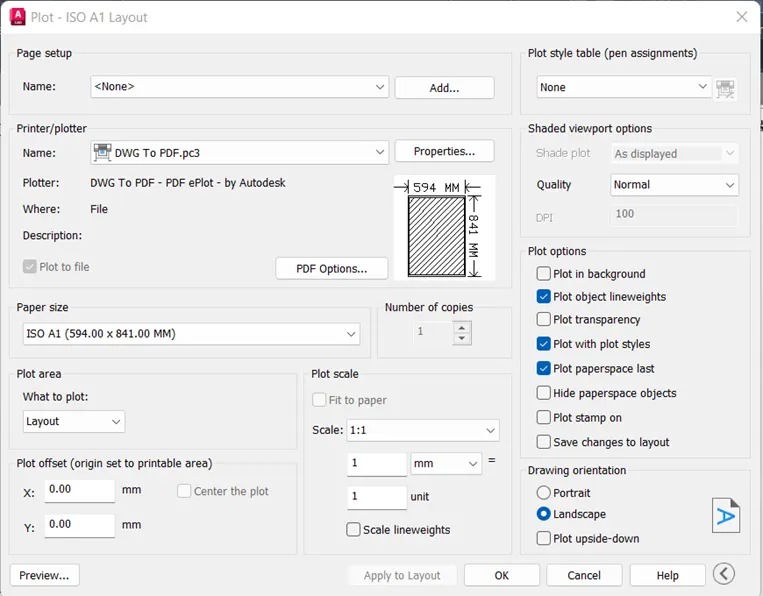
- After completion of layout of floor plan and section-AA, now we have to create it as pdf by using the command PLOT.
RESULT:
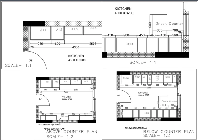
Create a layout of the Kitchen drawn in Challenge 9 as shown in Figure. Use the scale as shown in the Figure. Use A4 Size page for the layout. Take a plot.
AIM:
To create a layout of the kitchen of the project by using the tools from AutoCAD.
INTRODUCTION:
Layout:
Display one or more scaled views of design on a standard size drawing sheet called a layout. After finish of creating a model at full size, it can be switch to a paper space layout to create scaled views of the model, and to add notes, labels, and dimensions.
PROCEDURE:
step – 1:
- To create a layout, firstly we have to complete the sketch of the project.
- After complete the sketch of the project, we have to save the drawings by using the command NEWVIEW for easy to create the layouts.
- Firstly, we have to save the sketch as above counter plan by using the command NEWVIEW.
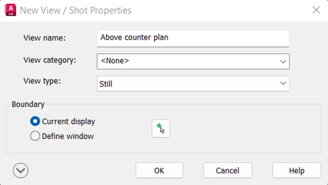
- By using the same command save another sketch as below counter plan.
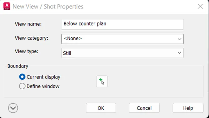
- Select the command LAYOUT to create a new layout.
- Now we have to select the sheet size or paper size, use the option Page Setup and select the paper size to A4
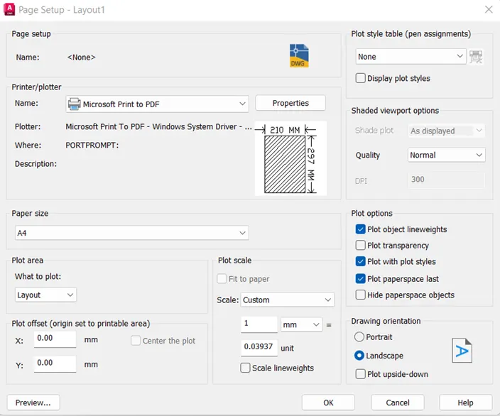
Step – 2:
- After completing the selection of paper size of layout, now we have to create required viewports.
- Select the command MVIEW and select the option named, because we have already saved the required viewports.
- By using the command MVIEW create above floor plan viewport and place it on specified place.
- We can also adject the viewport by using the command MS and to adject the paper by using the command PS.
- After completing the placement of viewport, we have to lock the viewport by using the command MVIEW.
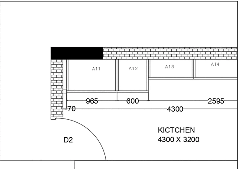
- After completion of above floor plan viewport, now we have to create a new viewport for below floor plan by using the command MVIEW.
- Adject the viewport by using the command MS and to adject the paper by using the command PS.
- After completing the placement of viewport, we have to lock the viewport by using the command MVIEW.
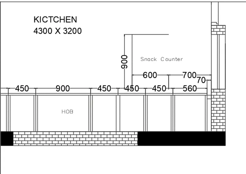
- Now we have to create a new viewport for above floor plan by using the command MVIEW.
- Adject the viewport by using the command MS and to adject the paper by using the command PS.
- After completing the placement of viewport, we have to lock the viewport by using the command MVIEW.
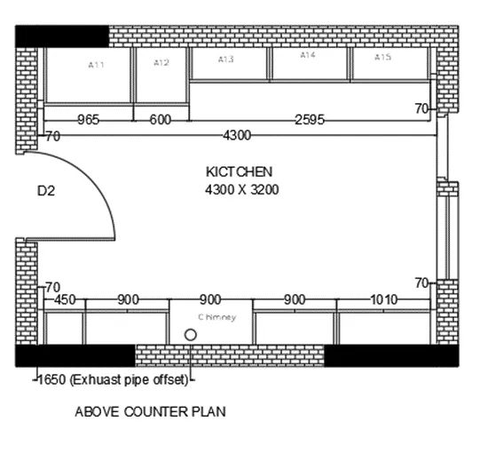
- Now we have to create a new viewport for below floor plan by using the command MVIEW.
- Adject the viewport by using the command MS and to adject the paper by using the command PS.
- After completing the placement of viewport, we have to lock the viewport by using the command MVIEW.
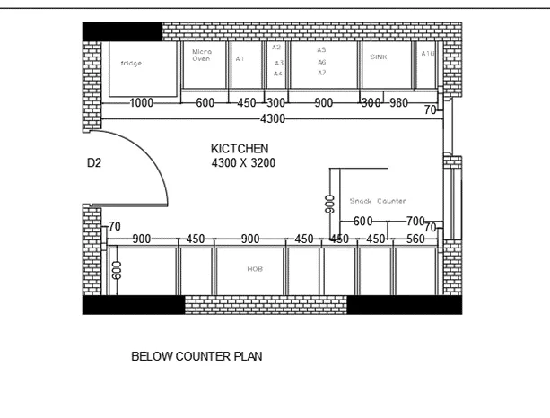
- After completing the layout, we have text the layout at specified places by using the command DTEXT.
- Adject the drawings in the viewports in perfect size by using the command SCALE.
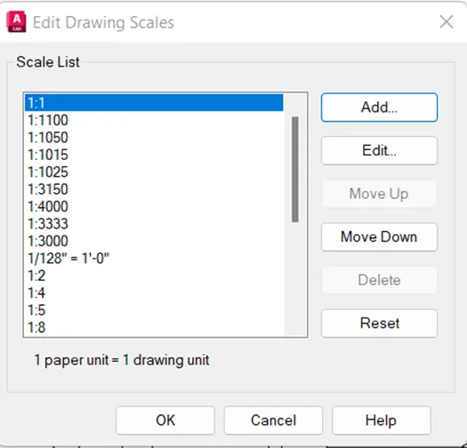
Step – 3:
- After completion of layout of floor plan and section-AA, now we have to create it as pdf by using the command PLOT.
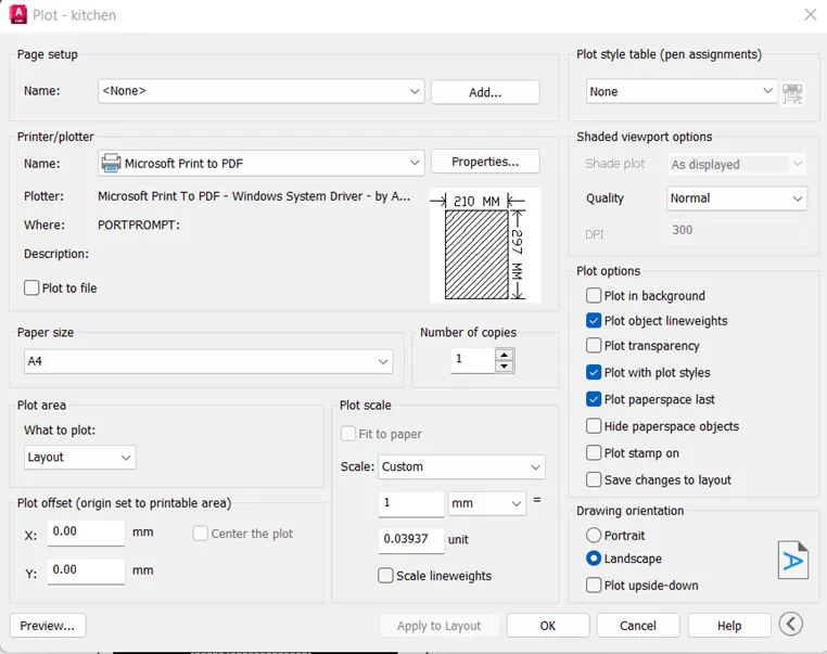
RESULT:
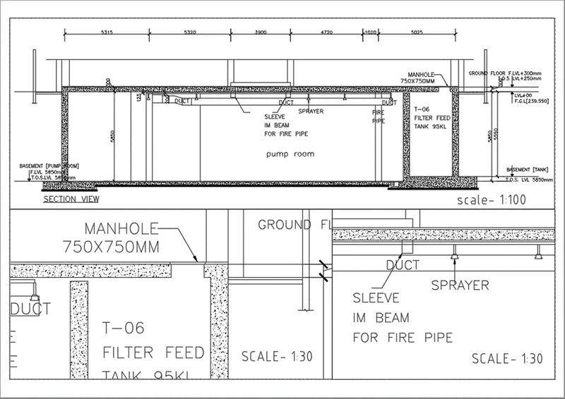
Create a layout of the section created in Challenges 9.
Use scale as mentioned in the Figure. Use MV command create multiple viewports. Take a plot.
AIM:
To create a layout of the section of industrial building of the project by using the tools from AutoCAD.
INTRODUCTION:
Layout:
Display one or more scaled views of design on a standard size drawing sheet called a layout. After finish of creating a model at full size, it can be switch to a paper space layout to create scaled views of the model, and to add notes, labels, and dimensions.
PROCEDURE:
step – 1:
- To create a layout, firstly we have to complete the sketch of the project.
- After complete the sketch of the project, we have to save the drawings by using the command NEWVIEW for easy to create the layouts.
- Firstly, we have to save the sketch as industrial section by using the command NEWVIEW.
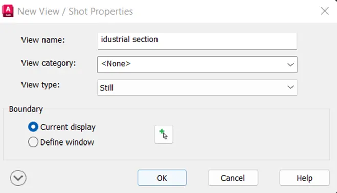
- Select the command LAYOUT to create a new layout.
- Now we have to select the sheet size or paper size, use the option Page Setup and select the paper size to A4
Step – 2:
- After completing the selection of paper size of layout, now we have to create required viewports.
- Select the command MVIEW and select the option named, because we have already saved the required viewports.
- By using the command MVIEW create industrial section viewport and place it on specified place.
- We can also adject the viewport by using the command MS and to adject the paper by using the command PS.
- After completing the placement of viewport, we have to lock the viewport by using the command MVIEW.
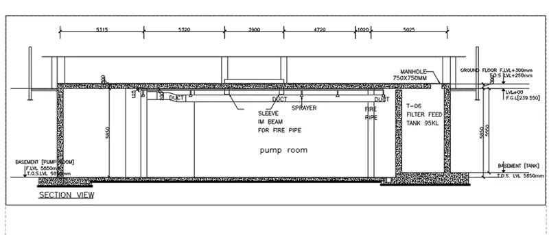
- After completion of industrial section viewport, again we have to create a new viewport industrial section by using the command MVIEW.
- Adject the viewport by using the command MS and to adject the paper by using the command PS.
- After completing the placement of viewport, we have to lock the viewport by using the command MVIEW.
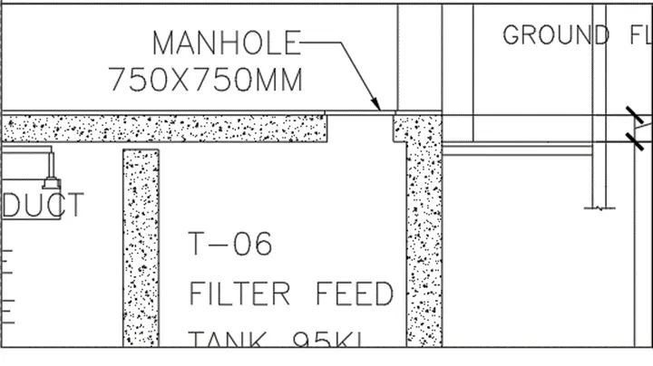
- After completion of industrial section viewport, again we have to create a new viewport industrial section by using the command MVIEW.
- Adject the viewport by using the command MS and to adject the paper by using the command PS.
- After completing the placement of viewport, we have to lock the viewport by using the command MVIEW.
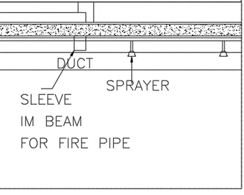
- After completing the layout, we have text the layout at specified places by using the command DTEXT.
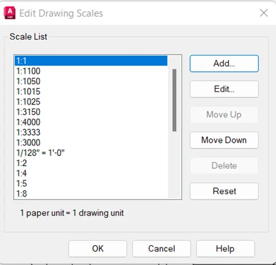
- Adject the drawings in the viewports in perfect size by using the command SCALE.
Step – 3:
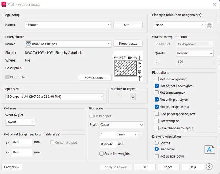
- After completion of layout of floor plan and section-AA, now we have to create it as pdf by using the command PLOT.
RESULT: