Creation of Multiple viewports, Scaling the drawing and setting in Template in AutoCad
Aim-To create a layout of plan and section A of the projrct in challenge-7 by using template.
Introduction-Here Challenge-7 plan is taken as a reference to create viewports and layout with template.
Preocedure-
-Set unit in mm, limits, dimension style
-XREF enter, attach dwg challenge-7, bind ok and then explode the plan
-Go to view, take 2 vertical screen then set floor plan in 1st screen and save as name B1 and in 2nd rect set section A and save as B.
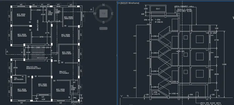
Now go to layout 1 type layout command select template i.e. tutorial march ok then click on that name of template and remane it as a PLAN & SECTION
-MS enter take rectangle command @400,445 and @375,445
-MV enter select object then select recatngle for zoom in that particular rectangle type MS enter zoom in set floor plan and then scale it with 1:50 and then MV command select lock on enter ok
-Follow same procedure for 2nd rectangle
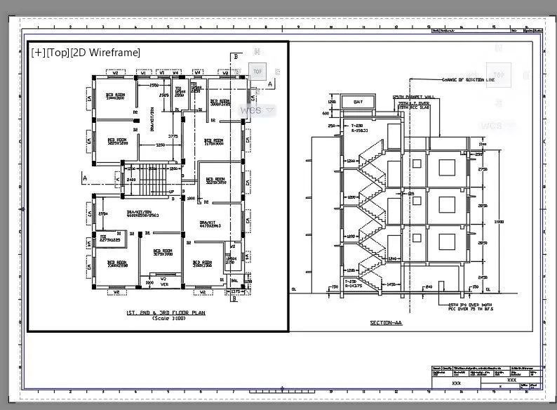
-ATTEDIT enter clivk on template rectangle
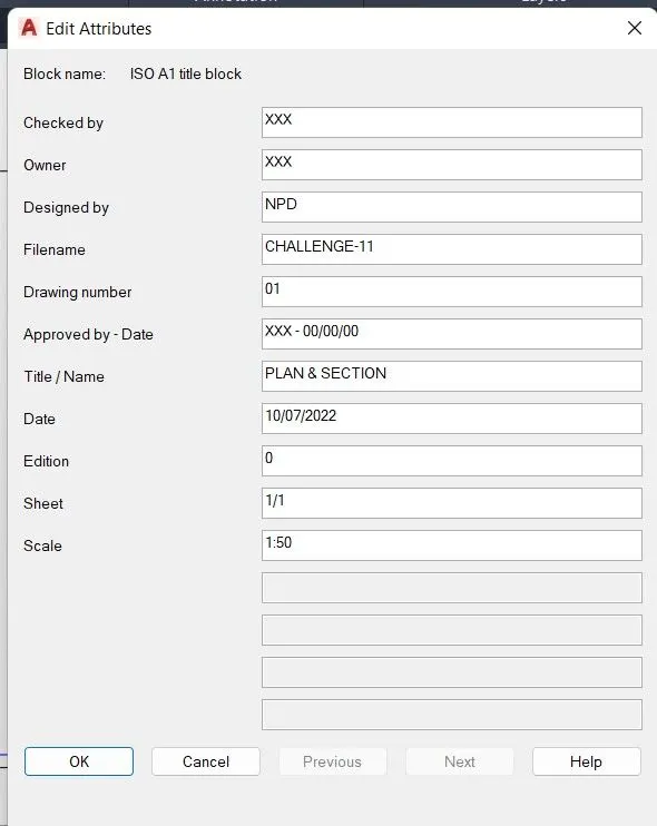
-Fill up all the details in this box according to projects
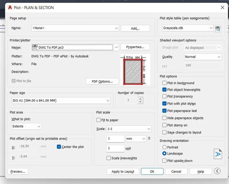
-Type plot, select A1 paper size, i am taking Grayscale as a plot style and take a preview.
Result-
Challenge-7's plan and section A is set as a template and plot it as in pdf form.
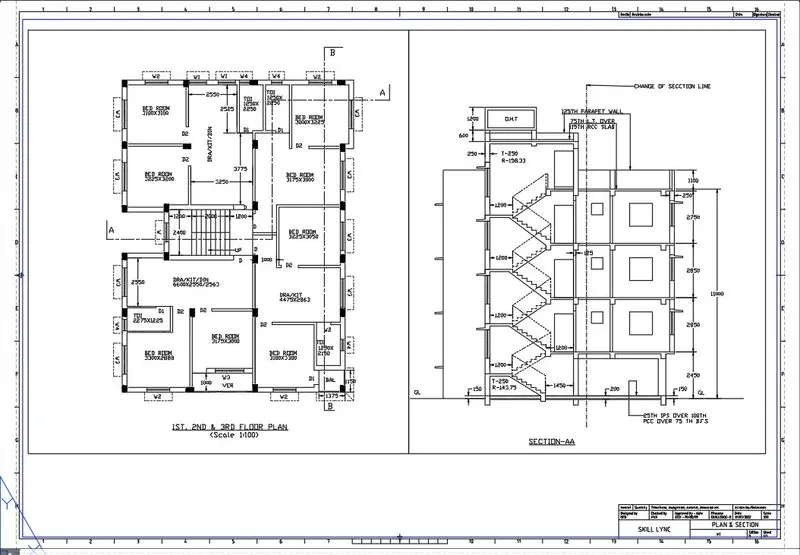
Note-PDF file is attach with this.
Aim-To create a layout of kitchen in challenge-10 as shown in figure.
Introduction-In this challenge, the kitchen plan drawn in challenge-10 is taken to draw layout and plot it.
Procedure-
-Set unit in mm, limits, dimension style
-XREF enter, attach dwg challenge-10, bind ok and then explode the plan
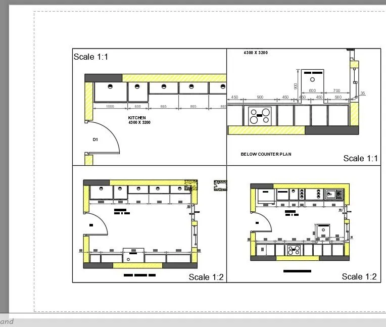
-Now go to view>view configuration>four equal screen
-Set view as shown in figure and give names to each for that go to view>new view>name i.e. K1, K2, K3, K4 respectively and set window according to that.
-Click on layout 1 rename it as a Kitchen Layout
-Page set up manager set the accoring to given
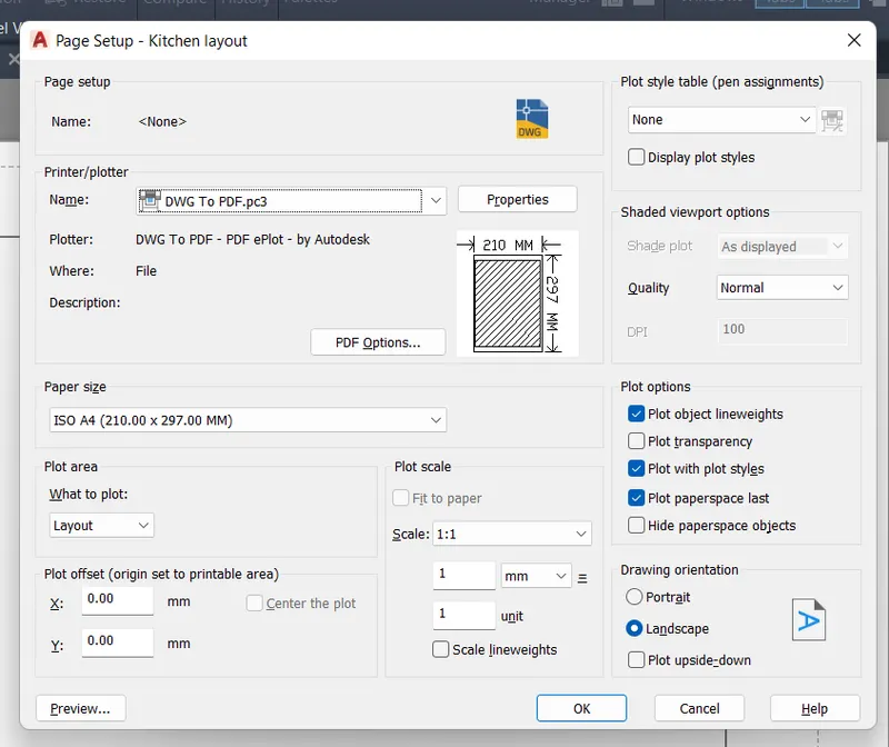
-MV enter>4 enter>view>view manager> select view name as shoen in figure and click ok
-MV enter>lock>on enter
-DT enter for text
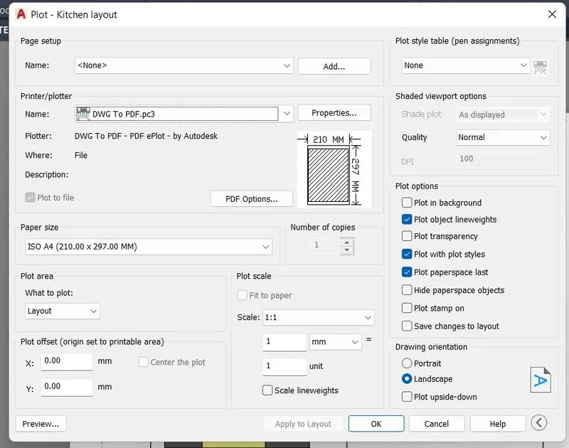
-Plot enter set as given
Resut-
This is the kitchen layout
Note-PDF file is attach with this.
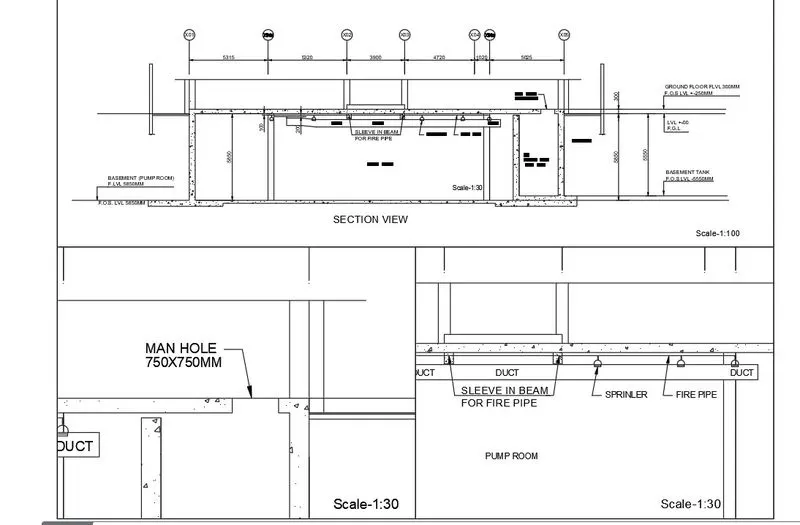
Aim-To create a layout of section drawn in challenge-10
Introduction-In challenge-10 there is industrial section drawn which is we are now going to create a layout of this section.
Procedure-
-Set unit in mm, limits, dimension style
-XREF enter, attach dwg challenge-10, bind ok and then explode the plan
-Click on layout 1 rename it as a Kitchen Layout
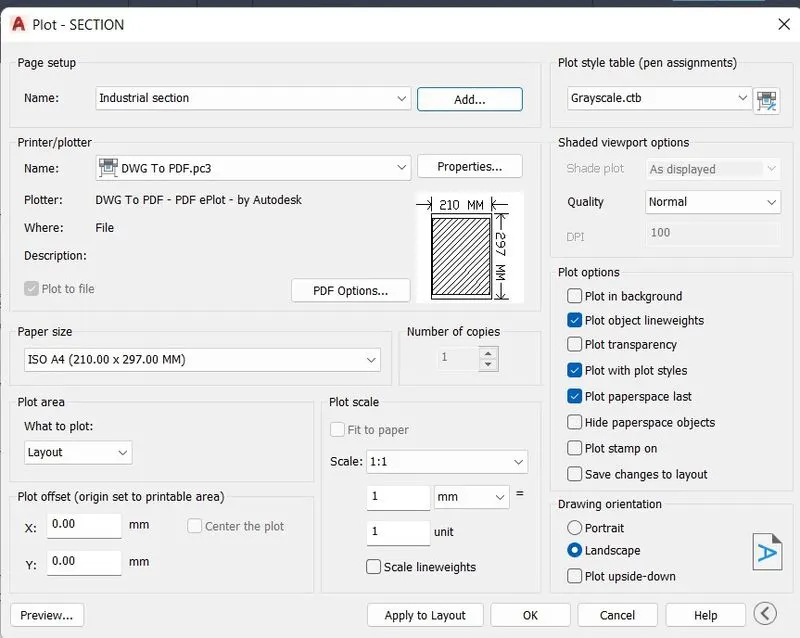
-Page set up manager set the accoring to given as taken A4 size page.
-MV enter>3 enter>select Above>Specify 1st and last point enter.
-Go to view>New view>Name=S1>ok, set view as shown in figure
-MV enter>Lock>On enter
-Follow same procedure for remainng 2 views and set ther name as S2, S3 respectively.
-DT enter for text
-Plot enter
Result-
-This is the layout of section drawn in challenge-10.
Note-PDF file of this attach in this.