Creation of Multiple viewports, Scaling the drawing and setting in Template in AutoCad
1)
Aim - 1) Create a layout of plan and sections A of the project in Challenge 7
2) By using Command MV to create the viewport .
Introduction - i) As we have already drawn the Week 7 project by using various commands in autocad.
ii) Now we have to create the layout of the plan and section A view .
iii)Take the reference of week 7 challenge.
iv) Scale given as - 1:50
iv)Following Commands are used -
a) Layout
b) View
c) Multiple View
d) MS ( Model size )
e) PS ( Paper Size )
f) Plot
g) Xref
Procedure -
i) Command Xref -
ii) On left hand side there is an option - Attach file
iii) Select the Week 7 file
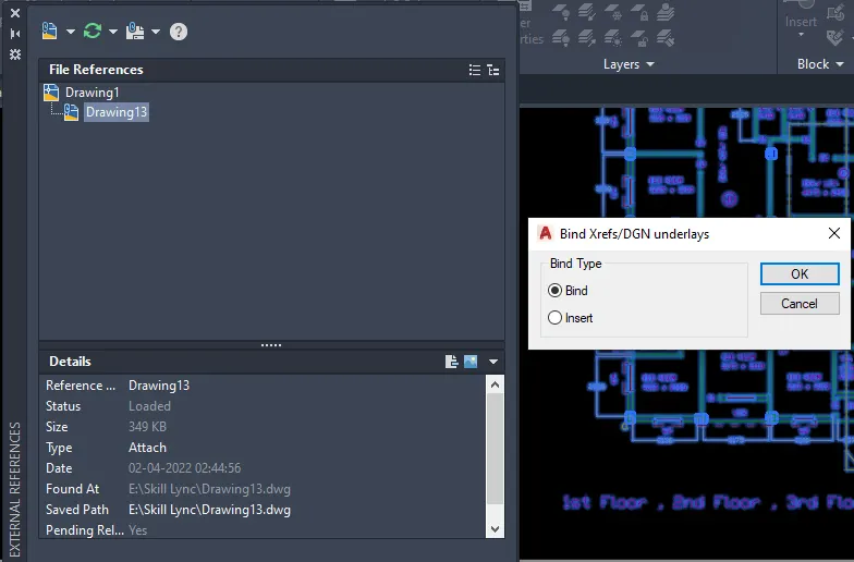
iv) After attaching the file , Right click on it and Select bind options and then explode it .
Step by Step Peocedure -
Step 1)
i) After attaching the file , at bottom there is an option as Layout
ii) Right click and rename it as Plan and Section A
iii) Delete the current view .

Step 2)
i) After the renaming the layout , We have to create the Template .
ii) To create the template - Command Layout
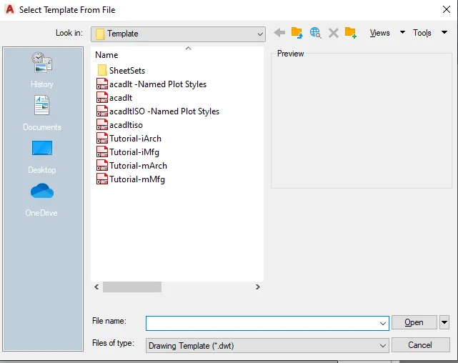
iii) Select Template
iv) Select - tutorial M.arch (Given)
v) Select - ISO A1 layout
vi) And again rename it as Plan and Section A

Step 3)
i) Command Ms - To activate the model port
ii) To create the view port
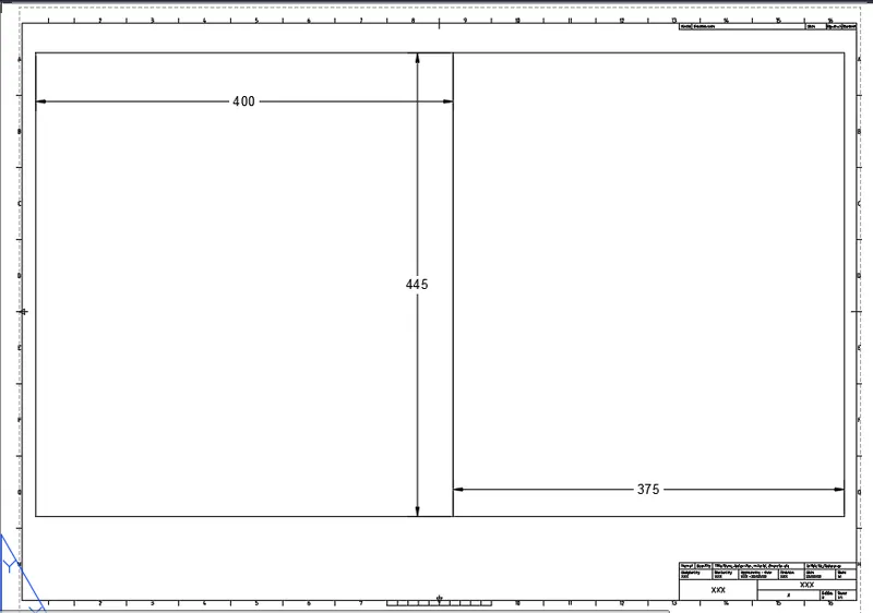
iii) Command Rectangle - 1
iv) Enter the length - 400mm
v) Enter the width - 445mm
vi) Command Rectangle -2
vii) Enter the length - 375mm
viii) Enter the width - 445mm
Step 4)
i) Now command MV - to create the multiple view port
ii) Select New
iii) Select the object by creating window selection
iv) Press Enter .
v) Command MS - to activate the Model Space
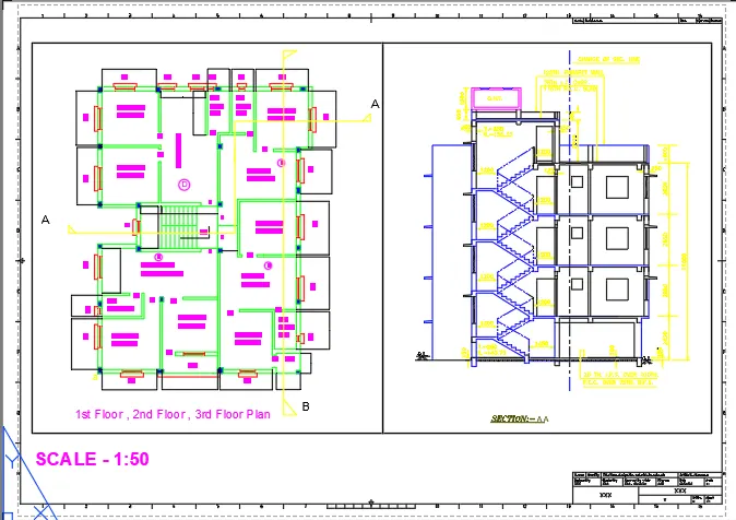
View Port 1 - PLAN
i) In view port 1 we want Plan drawing
ii) So command MS -
iii) Zoom the plan
iv) And we have to set the scale as 1:50
v) Ajust the plan by using Pan options
vi) Once the view is set , Locked the view .
View Port 2 - Section
Similarly Follow the same procedure fir View port 2 - For Section A
Step 5) Edit the Attributes -
i) Command PS - Paper Scale so that u cannot edit the plan and sections
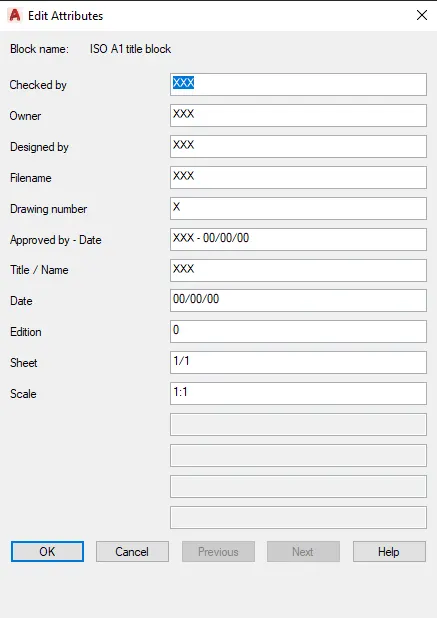
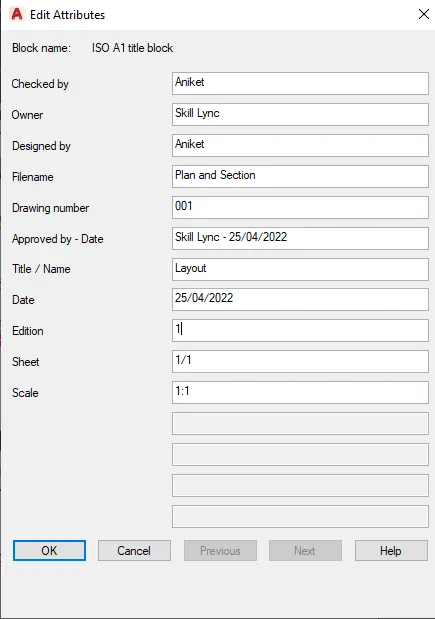
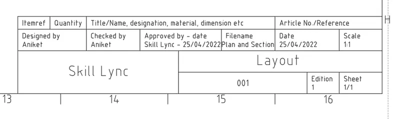
ii) Command ATTEDIT - Select the Template which are created as a block
iii) Edit the attribues
iv) Fill the data
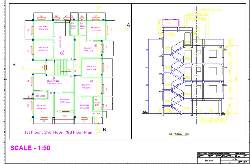
Step 6) Plot the plan on A1 sheet
i) Command Plot
ii) Dialogue Box will appear .
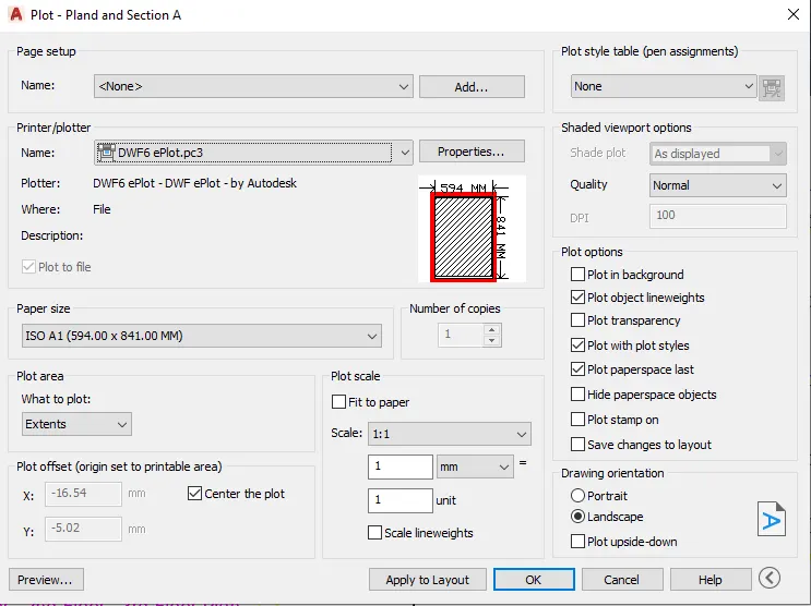
iii) Name as - Dwf6 to ePLOT.pc3
iv) Paper Size - ISO A1
v) Plot Area - Layout
vi) Pen Assignments - Monochrome.stb so that print will be in Black .
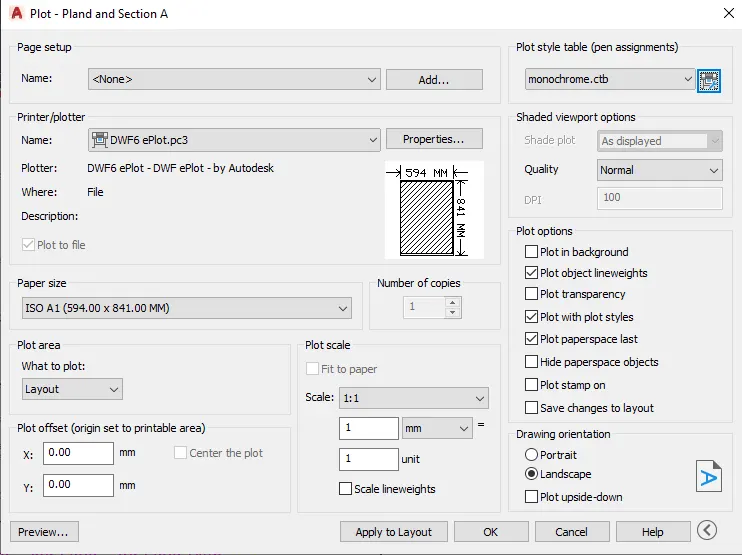
Preview -
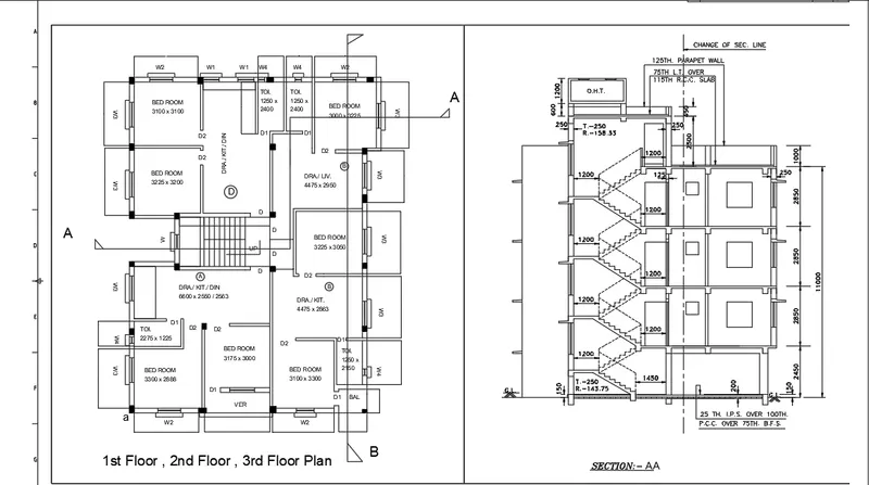
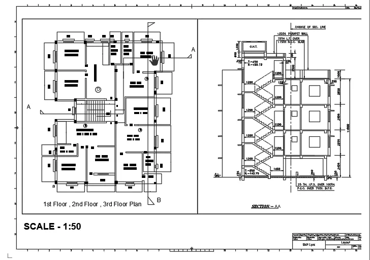
Result -
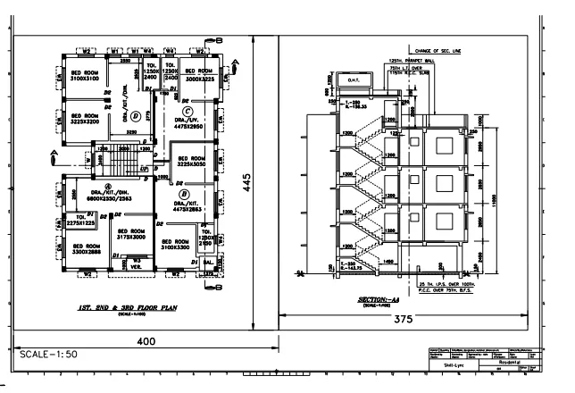
i) A Layout is created for week 7 challenge ( Plan and Section A ) by using template
"Tutoroal m.arch"
ii) A viewport is also created by using command MV (Multiple view ) of size
(400mm x 445mm) and (375mm x 445mm) and the Scale is set at 1:50
iii) Attributes in the Template are also Edited by using Command ATTEdit
iv) A1 size is considered for layout and Plot is taken ( Printed) .
2)
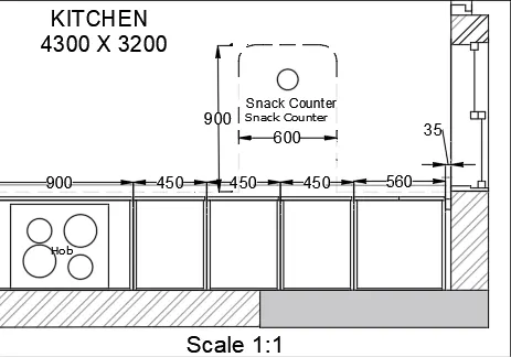
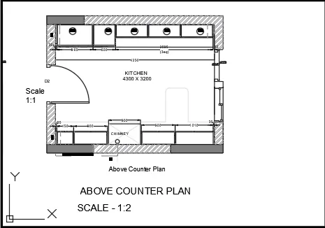
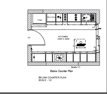
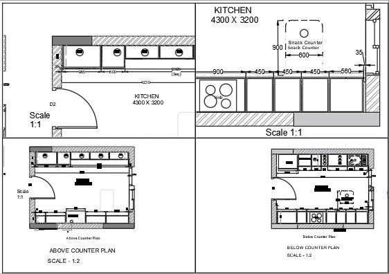
Aim - To create the layouts of Kitchen in 4 different viewports and use A4 sheet size paper
to plot .
Introduction - i) Take the reference of the week 9 challenge .
ii) We have to create the layout of the Kitchen
iiii) As we have already drawn the Week 9 challenge by using various commands in autocad.
iv) Scale - given as different for different viewport
iv)Following Commands are used -
a) Layout
b) View
c) Multiple View
d) MS ( Model size )
e) PS ( Paper Size )
f) Plot
g) Xref
Procedure -
i) Command Xref -
ii) On left hand side there is an option - Attach file
iii) Select the Week 7 file
iv) After attaching the file , Right click on it and Select bind options and then explode it .
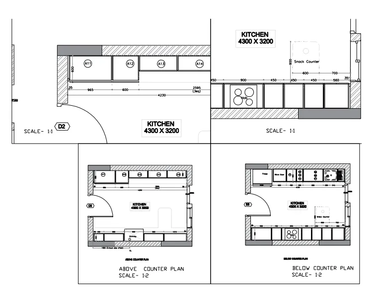
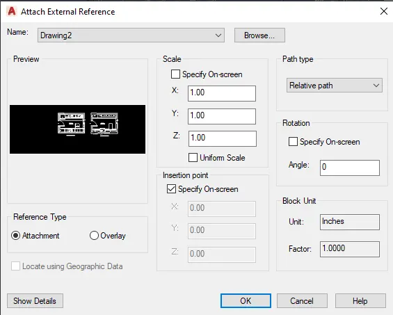
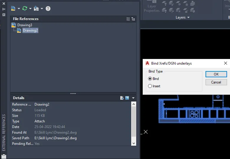
Step by Step Peocedure -
Step 1)
i) After attaching the file , at bottom there is an option as Layout
ii) Right click and rename it as Kitchen Layout .
iii) Delete the current view .
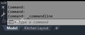
Step 2)
i) Now we have to save the views as per the given .
ii) Command View
iii) Select View Manager - Layout view
iv) Name it as View 1 - Select the Boundaries ( What views we want)
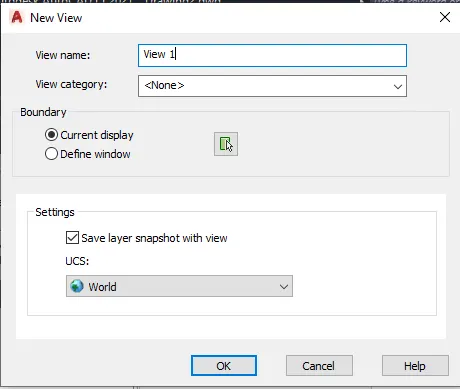
v) Similarly create View 2 , View 3 , View 4
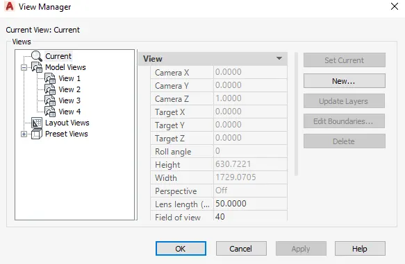
Step 3)
i) Open the layout tab -
ii) Command Ms - To activate the model port
iii) To create the view port 1
iv) Select View 1 from View manager
v) Command MV - Select Layer 4 to create 4 viewports
vi) Now in a 1st viewport , select View 1
vii) Command Dtext - and give the text as Scale 1:1
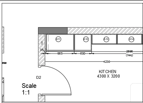
Similarly , For View port 2 , View port 3 , View port 4 - Follow the same procedure
2) View port 2
3) View port 3
4) View port 4
Step 4) Plot the plan on A4 sheet
i) Command Plot
ii) Dialogue Box will appear .
iii) Name as - Dwf6 to ePLOT.pc3
iv) Paper Size - ISO A4
v) Plot Area - Layout
vi) Pen Assignments - Monochrome.stb so that print will be in Black .
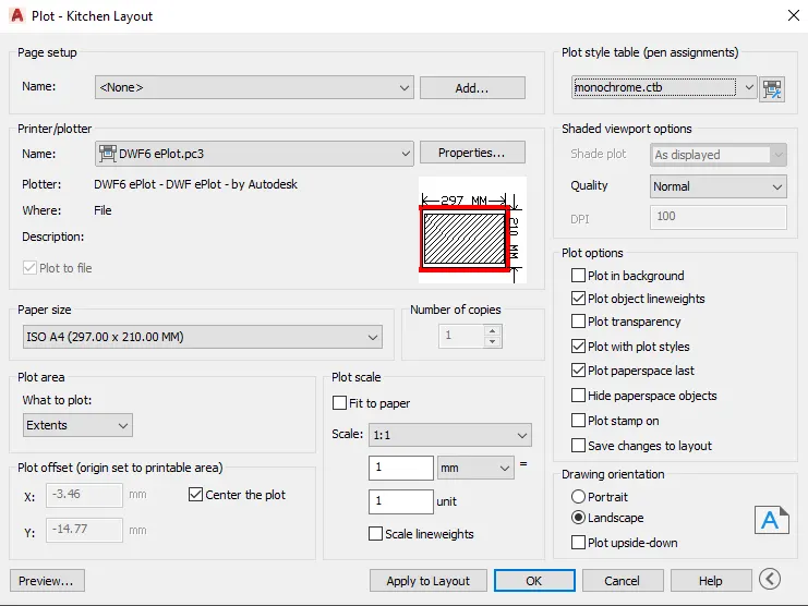
Preview -
Results -
i) A Layout is created for week 9 challenge ( Kitchen Layout )
ii) 4 different viewport is also created by using command MV (Multiple view ) the Scale is set
as per given .
iii) A4 size is considered for layout and Plot is taken ( Printed) .
3)
Aim - To create the layout of section of Industrial building which we have created in week 9
Challenges .
Introduction - i) As we have already drawn Cross Section of Industrial Building in Week 9 challenge by using
various commands in autocad.
ii) Now we have to create the layout of the Cross Section of Industrial building
iii)Take the reference of week 9 challenge.
iv) Scale given as - 1:30
v) Following Commands are used -
a) Xref
b) View
c) Ms
d) Ps
e) Plot
f) Layout
Procedure -
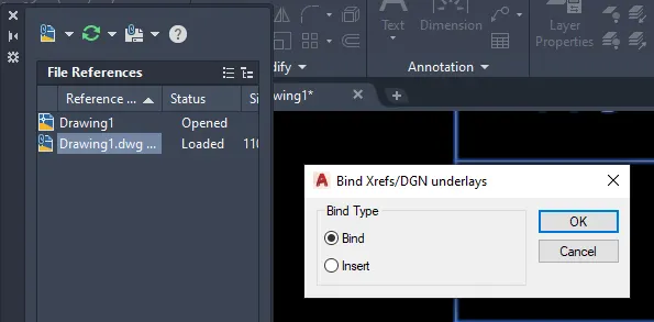
i) Command Xref -
ii) On left hand side there is an option - Attach file
iii) Select the Week 7 file
iv) After attaching the file , Right click on it and Select bind options and then explode it .
Step by Step Procedure -
Step 1)
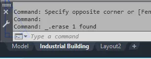
i) After attaching the file , at bottom there is an option as Layout
ii) Right click and rename it as Industrial Building .
iii) Delete the current view .
Step 2)
i) Open the layout tab -
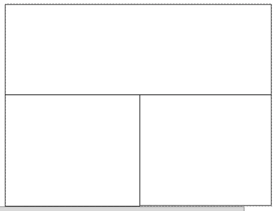
ii) Now command MV - to create the multiple view port
iii) Select New
iv) Select the object by creating window selection ( The view we want )
v) Press Enter .
vi) Command MS - to activate the Model Space
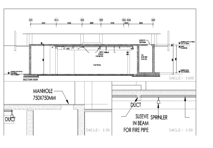
View Port 1 - Full View
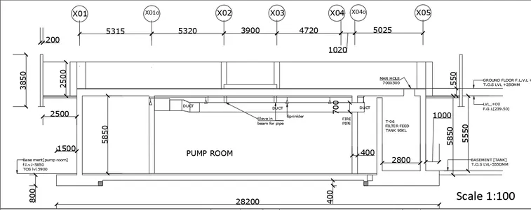
i) In view port 1 we want view plan
ii) So command MS - to work on view port
iii) Zoom the plan
iv) And we have to set the scale as 1:100
v) Adjust the plan by using Pan options
vi) Once the view is set , Locked the view .
vii) Command Dt - and give the Text as - Scale 1:100
View Port 2 -
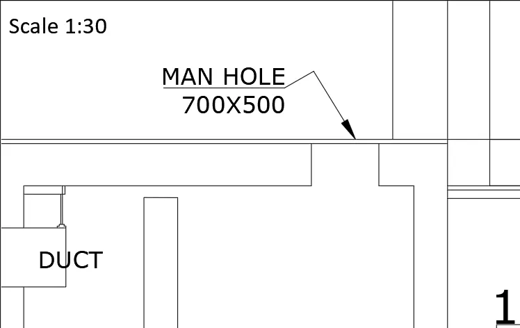
i) Similarly Follow the same procedure fir View port 2 -
ii) Set the Scale - 1:30
iii) Command Dt - and give the Text as - Scale 1:30
View Port 3
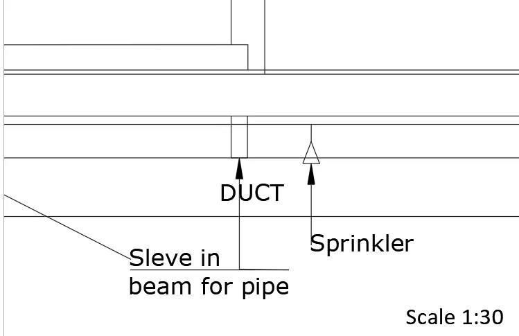
i) Similarly Follow the same procedure fir View port 3 -
ii) Set the Scale 1:30
iii) Command Dt - and give the Text as - Scale 1:30
Step 4) Plot the plan on A1 sheet
i) Command Plot
ii) Dialogue Box will appear
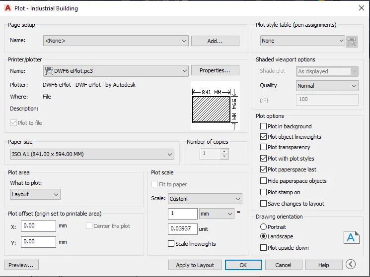
iii) Name as - Dwf6 to ePLOT.pc3
iv) Paper Size - ISO A1
v) Plot Area - Layout
vi) Pen Assignments - Monochrome.stb so that print will be in Black .
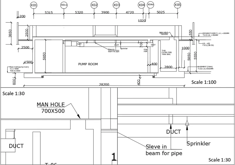
Preview -
Results -
i) A Layout is created for week 9 challenge ( Cross Section of Industrial building )
ii) 3 different viewport is also created by using command MV (Multiple view ) the Scale is set
as per given .
iii) A1 size is considered for layout and Plot is taken ( Printed) .