Creation of Multiple viewports, Scaling the drawing and setting in Template in AutoCad
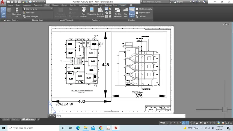
1. FLOOR PLAN AND SECTION LAYOUT
AIM
To create the floor plan and section layout as shown in the challenge
Steps
- Open the floor plan and section drawing which drafted in challenge 7
- Go to layout tab, do right click, then select the templete
- In template tab select Tutorial-mArch template
- Then layout will be created in the selected format with name ISO Layout and rename it as per the drawing
- Then delete the default viewport
- Then command MVPORTS, then select the option 2 viewports and then give fit
- Go the model space, then go to the ribbion, select view tab, then new view
- Create new views such as floor plan and section, define windows and save the views
- Go the layout, then command MSPACE and set the view
- Select the viewports, command PR (properties) then set the scale
- Then lock the display
- Then Command PS (paper space), command ATTEDIT, then select title block as block reference
- Give details in attributes dialogue box
- Then command text, give drawing details and specification details wherever needed
- Then go the ribbion and select dimlinear in dimension box, then give dimensions as shown in the challenge
RESULT
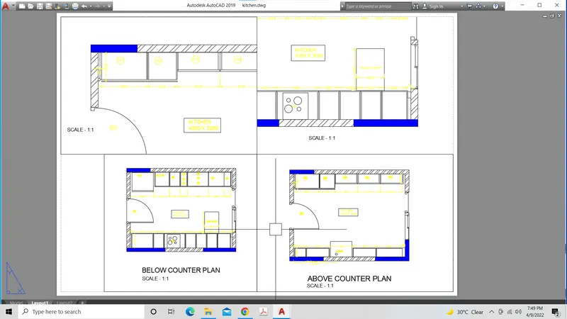
2. KITCHEN LAYOUT
AIM
To create the kitchen layout as shown in the challenge
Steps
- Open the kitchen drawing which drafted in challenge 9
- Go to layout tab, do right click, then set the page properties as A4 size
- Then delete the default viewport
- Then command MVPORTS, then select the option 4 viewports and then give fit
- Go the model space, then go to the ribbion, select view tab, then new view
- Create new views such as kitchen full views of each and part of the kitchen as shown, define windows and save the views
- Go the layout, then command MSPACE and set the view
- Select the viewports, command PR (properties) then set the scale
- Then lock the display
- Then command text, give drawing details and specification details wherever needed
- Then go the ribbion and select dimlinear in dimension box, then give dimensions as shown in the challenge
RESULT
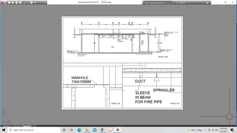
2. INDUSTRIAL LAYOUT
AIM
To create the industrial layout as shown in the challenge
Steps
- Open the industrial drawing which drafted in challenge 9
- Go to layout tab, do right click, then set the page properties as A4 size
- Then delete the default viewport
- Then command MVPORTS, then select the option 2 viewports in horizontal and then give fit, then delete one viewport , then view give 2 viewports vertically on the remaining area as shown in the challenge.
- Go the model space, then go to the ribbion, select view tab, then new view
- Create new views such as industry full view manhole and duct view, define windows and save the views
- Go the layout, then command MSPACE and set the view
- Select the viewports, command PR (properties) then set the scale
- Then lock the display
- Then command text, give drawing details and specification details wherever needed
- Then go the ribbion and select dimlinear in dimension box, then give dimensions as shown in the challenge
RESULT