Creating a Floor plan, Footing detail and Isometric view using AutoCad
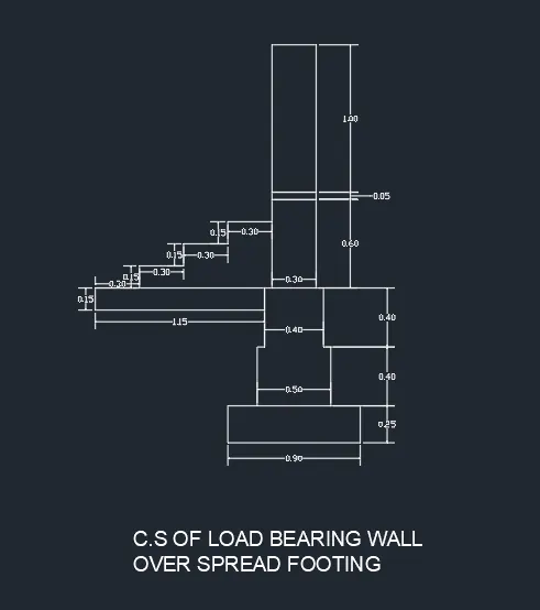
1. C.S. OF LOAD BEARING WALL OVER SPREAD WALL
AIM
To create the cross section drawing of load bearing wall over spread wall by refering the provided drawing
Steps
- Refer the provided drawing i.e., footing section with load bearing wall along with steps on the sides and its dimensions
- Draw rectangles for the footing by invoking rectangle command (type REC) and specify corner and then type D for dimensions and give length and width dimensions
- Using the above step draw rectangles of dimension (0.9 x 0.25, 0.5 x 0.4, 0.4 x 0.4, 0.3 x 0.6, 0.30 x 0.05, 0.30 x 1.00, 1.15 x 0.15)
- On the object snap , by using the Osnap, move and align the rectangles at thier mid points since the footing section was symmetrical (for the rectangle as showing as slab move and align at the corner)
- Trim the rectangles by using command trim (type TR) at wherever needed
- For steps by using line command and coordinates system @0.30,0 for thread and @0,0.15 for riser continuously we can draft the steps as shown in the drawing
- For Marking dimension by using the command DIMLINEAR type dim it will show dimlinear and then mark all dimensions
RESULT
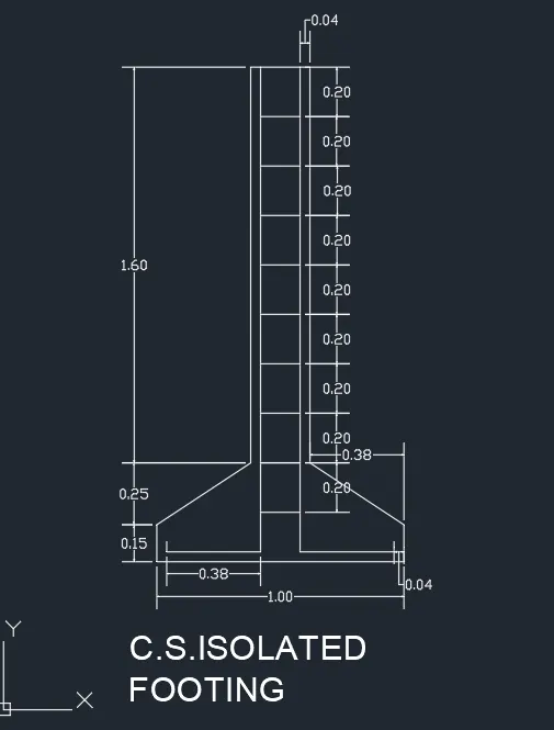
2. C.S. OF ISOLATED FOOTING
AIM
To create the cross section drawing of isolated footing by refering the provided drawing
Steps
- Refer the provided drawing i.e., footing section and its dimensions
- Initialy draw a line of length 1.60 in y axis and copy the line by using offset command specify distance 0.04 in x axis and then copy line of distance .16 in x axis using offset and then repeat the same steps above copy the line of distance of 0.04 in x axis
- Join the inner two lines by using line command and then copy & array it and givee 9 items of displacement 0.20 in y axis
- Extend the lines to footing secting line command and coordinate system @0,-0.25, @0,-0.15, @-0.38, 0, @0, 0.04 and then mirror it for other sides by specifying the midpoint using osnap on x axis
- For footing section draw rectangle of dimension lenght 1 and width 0.4 and then move it and align to the midpoint of inner two lines (for showing reinforcement ) and then trim it usign command trim
- Then use chamber command by invoking it on the home ribbon and then select the two sides where chamber needed first select lenght side and then width side and give first distance as 0.38 and second distance 0.25 repeat the same on other side
- For Marking dimension by using the command DIMLINEAR type dim it will show dimlinear and then mark all dimensions
Result
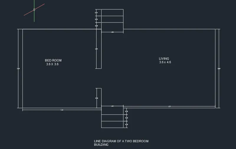
3. LINE DIAGRAM OF A TWO BEDROOM BUILDING
AIM
To create the line diagram of a two bedroom building by refering the provided drawing
Steps
- Refer the provided drawing i.e., two bedroo building and its dimensions
- Initialy draw a rectangle by suming the dimensons of bedroom, living room and steps; and give length 8.80m and width 3.60m
- Draw 3 rectangles of dimension 1.00 x 0.30, move and align it adajacent to each other on length face, align it on right corner of rectangles to the right corner of big rectangle and the move it to the distance of 3.60 on x axis and then trim it using the trim command
- Using mirror command align the steps on other side by specifying the midpoint of big rectangle intersects at the midpoint of steps (on the ortho mode), it will come on other perfectly
- Extend the right corner of steps to the inside as wall 1.80 on top and 0.90 on bottom
- For Marking dimension by using the command DIMLINEAR type dim it will show dimlinear and then mark all dimensions
Result
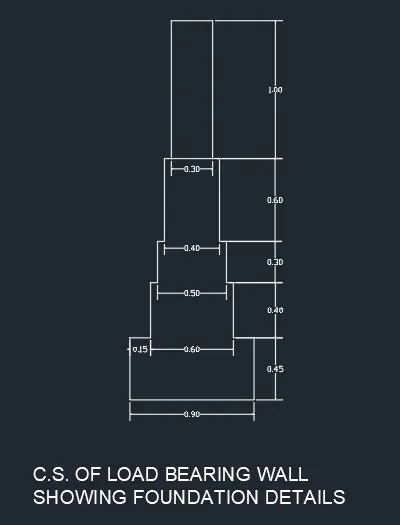
4. C.S. OF LOAD BEARING WALL SHOWING FOUNDATION DETAILS
AIM
To create the cross section drawing of load bearing wall with foundation details by refering the provided drawing
Steps
- Refer the provided drawing i.e., footing section with load bearing wall and its dimensions
- Draw rectangles for the footing by invoking rectangle command (type REC) and specify corner and then type D for dimensions and give length and width dimensions
- Using the above step draw rectangles of dimension (0.9 x 0.45, 0.6 x 0.4, 0.5 x 0.3, 0.4 x 0.6, 0.30 x 1.0)
- On the object snap , by using the Osnap, move and align the rectangles at thier mid points since the footing section was symmetrical (for the rectangle as showing as slab move and align at the corner)
- Trim the rectangles by using command trim (type TR) at wherever needed
- For Marking dimension by using the command DIMLINEAR type dim it will show dimlinear and then mark all dimensions
RESULT
5. ISOMETRIC VIEW OF STEPS
AIM
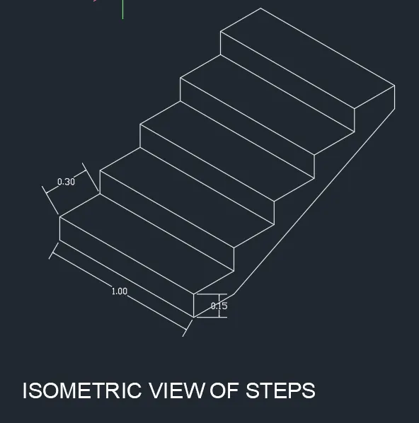
To create the isometric view of steps by refering the provided drawing
Steps
- Refer the provided drawing i.e., isometric view of steps and its dimensions
- Invoke Osnap and then options and then off the snap mode and grid mode on the isometric mode, then on the ortho mode and isometric mode
- Intially use line command specify origin point, using isoplane left draw line of length 1 on x axis and 0.15 on y axis and then 1 on axis and 0.15 on y axis
- For thread switch to isoplane right and draw line of lenght 0.30 on both sides and bottom of first riser
- Then repeat the same steps for other risers and threads
- Finally, off the isometric mode and draw a line for joining the bottom line from 1st step to 5th step
- For Marking dimension by using the command DIMLINEAR type dim it will show dimlinear and then mark all dimensions
RESULT
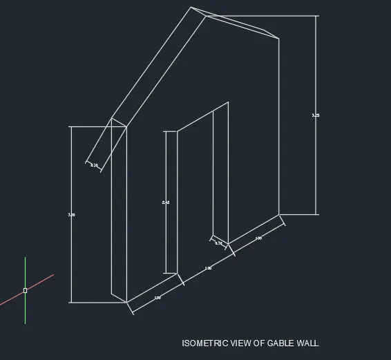
6. ISOMETRIC VIEW OF GABLE WALL
AIM
To create the isometric view of gable wall by refering the provided drawing
Steps
- Refer the provided drawing i.e., isometric view of steps and its dimensions
- Invoke Osnap and then options and then off the snap mode and grid mode on the isometric mode, then on the ortho mode and isometric mode
- Intially use line command specify origin point, using isoplane right draw line of length 1 on x axis & 2.42 on y axis & then 1 on axis & 2.42 on y axis & 1 on x axis and 3 on y axis
- At left corner at origin point draw a line specify length 3m on x axis and isoplane left 0.30 on x axis as showing thickness on top and bottom and draw line at door opening also showing as thickness
- Off the isometric mode and draw the roof fixing the midpoint of roof at best fitting point and draw the rectangles on both which represents thcikness
- For Marking dimension by using the command DIMLINEAR type dim it will show dimlinear and then mark all dimensions
RESULT