Creation of Column Schedule and Drawing Template using AutoCad
FIGURE-1
CREATE A COLUMN SCHEDULE AS SHOWN IN FIGURE.
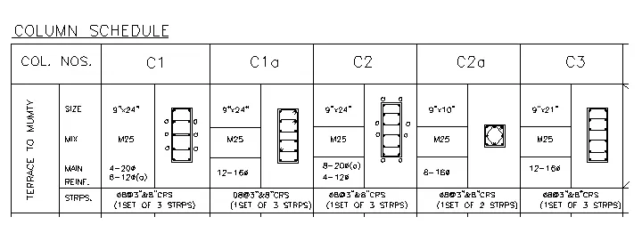
AIM:- TO CREATE A COLUMN SCHEDULE AND DRAW THE COLUMN REINFORCEMENT OF COLUMN IN DETAILS.
COMMAND USED IN FIGURE:-
- limits
- singel text
- line
- trim
- circle
- rectangular
- offset
- mirror
- dimmension tool.
- extend
PROCEDURE:-
- first open autocad and set limits and set units by unit command.
- now we have to draw table using line and rectangular command.
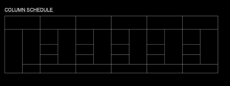
- now we have to draw every reinforment details by using diffrent command .
- first we draw C1 column detail
- draw 9" line horizontally by using line command.
- next draw line of 24" from the last point . using this method draw rectangular column of 9"x24".
- now take offset command and give offset of 0.6 from every side of rectangular.
- now we draw four segment in column by divide command uniformly.
- now take circle command and take diameter of 20mm and 12mm.
- after that put circle at every segment as shown in figure.
- bend the corner of stirrups to 45 degree.
- inside bar of 12 mm we denote that bars by 'a'.
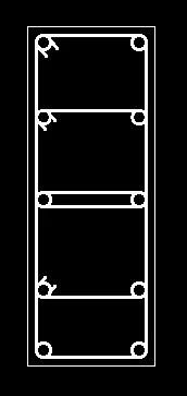
- same as above method we have to draw another column by same dimension.
- first draw rectangular by line command of 9"x24".
- after that give offset of 0.6.
- now we have to devide 5 segments in inner rectangular.
- now take the circle command draw circle of 16mm.
- put every circle at every segement.
- put three stirrups in the column where they shown in figure.
- bend the corner as shown in figure.
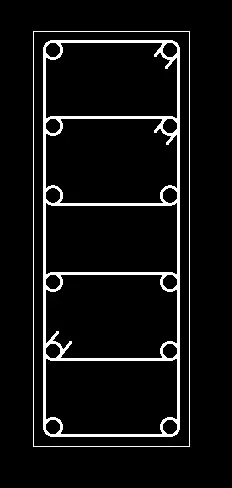
- same as above method we have to draw another column by same dimension.
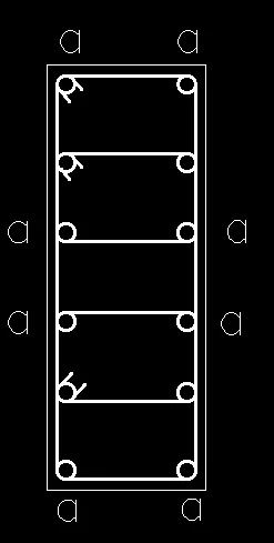
- first draw rectangular by line command of 9"x24".
- after that give offset of 0.6.
- now we have to devide 5 segments in inner rectangular.
- now take circle command and draw circle of 20mm for 8 bars.
- draw onther circle of 12mm for 4 bars.
- now put that circle as shown in figure
- bend the corner of stirrups to 45 degree.
- inside bar of 20 mm we denote that bars by 'a'.
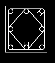
- for next column draw line of 9" horizontally.
- from the last point draw next line of 10" vertically.
- with same dimmension complete rectangel.
- after ake offset commad and give offset of 0.6 to every side .
- now take circle command and draw 8 circle of 16 mm .
- put place the circle as they shown in figure.
- now by using mirror command mirror mirror one side to the onother side and join four bars using line command.
- now band the corner of stirrups as they shown in figure.
- same as first column method we have to draw another column by same dimension.
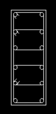
- first draw rectangular by line command of 9"x24".
- after that give offset of 0.6.
- now we have to devide 5 segments in inner rectangular.
- now take the circle command draw circle of 16mm.
- put every circle at every segement.
- put three stirrups in the column where they shown in figure.
- bend the corner as shown in figure.
- now we have to put every column drawing as they given in figure.
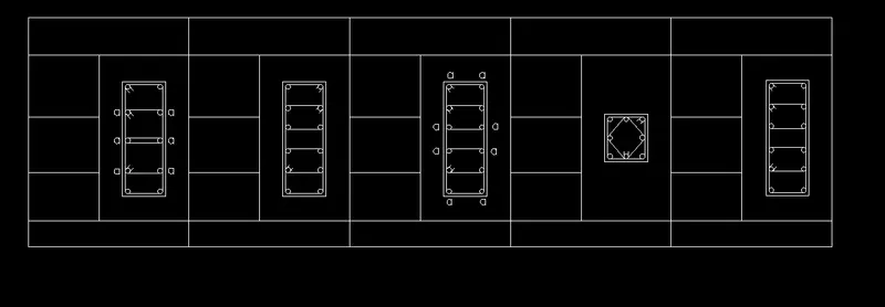
- now using singel text command write every data in table.
RESULT:- GIVEN COLUMN SCHEDULE IS SUCCESFUL DRAWN IN AUTOCAD.
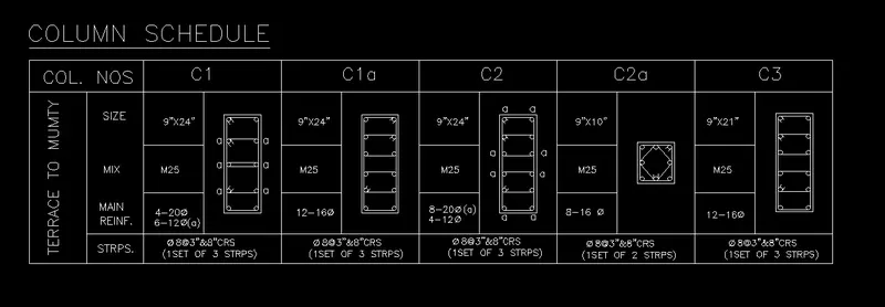
FIGURE-2
CREATE A WINDOW SCHEDULE AS SHOWN IN THE FIGURE.
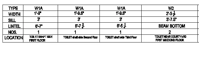
AIM:- TO CREATE A WINDOW SCHEDULE AND DRAW THE DETAILS OF WINDOW IN DETAILS.
COMMAND USED IN FIGURE:-
- line
- limits
- text
PROCEDURE:-
- open autocad and set limits and units.
- first we draw the table using line command .
- draw 5 column and 6 rows.
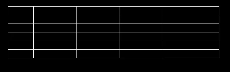
- now using text command we give every data in window schedule as they shown in figure.
- various window details shown below.
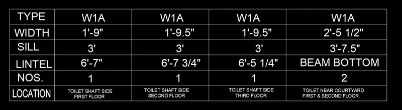
RESULT:- GIVEN WINDOW SCHEDULE IS SUCCESFUL DRAWN IN AUTOCAD.
FIGURE-3
CREATE A DRAWING TEMPLATE AS SHOWN IN THE FIGURE.

AIM:- TO CREATE A DRAWING TEMPLATE AND GIVE INFORMATION ABOUT THE PROJECT.
COMMAND USED IN FIGURE:-
- line
- limits
- text
- divide
- offset
PROCEDURE:-
- open autocad and set limits and units.
- first we draw the table as they given in figure using line command .
- if anywhere we need offset or divide command we can use that.

- now using text command we give every data in project detail table as they shown in figure.
- data of client and notes are given below.

RESULT:- GIVEN DRAWING TEMPLATE IS SUCCESFUL DRAWN IN AUTOCAD.
FIGURE-4
CREATE A LIST OF DRAWING SCHEDULE AS SHOWN IN THE FIGURE.
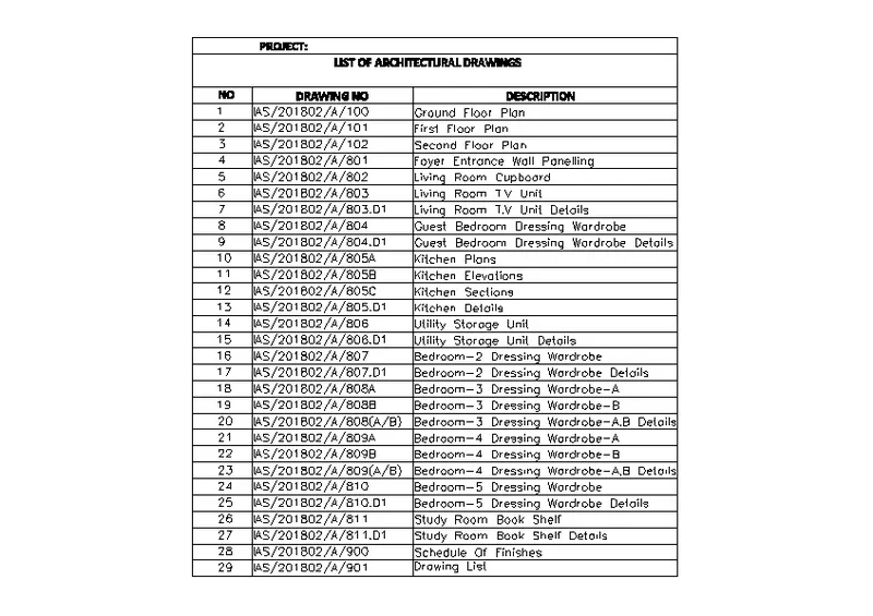
AIM:- TO CREATE A LIST OF DRAWING SCHEDULE.
COMMAND USED IN FIGURE:-
- line
- limits
- text
- trim
- divide
- offset
PROCEDURE:-
- open autocad and set limits and units.
- first we draw the table as they given in figure using line command .
- trim unnessesory part in table.
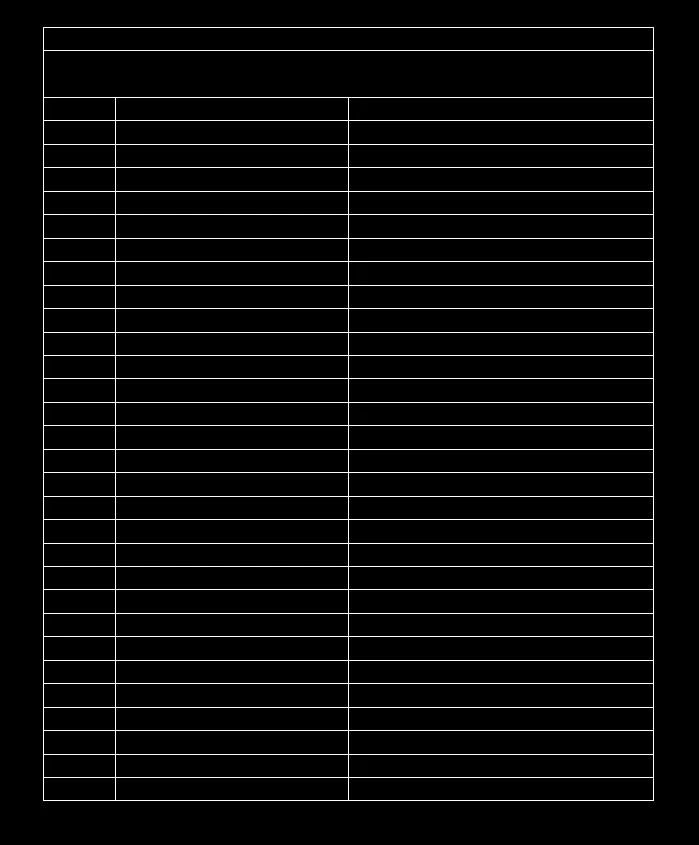
- now using text command we put drawing data in table as they given in figure.
RESULT:- GIVEN DRAWING TEMPLATE IS SUCCESFUL DRAWN IN AUTOCAD.
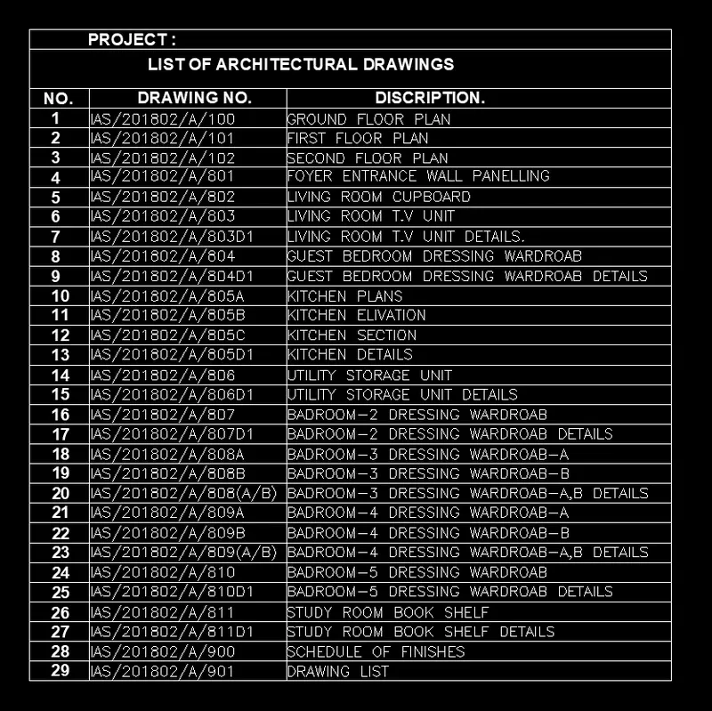
FIGURE-5
CREATE THE BEAM DETAIL AS SHOWN IN THE FIGURE AND PROVIDE TEXT WHEREVER GIVEN.
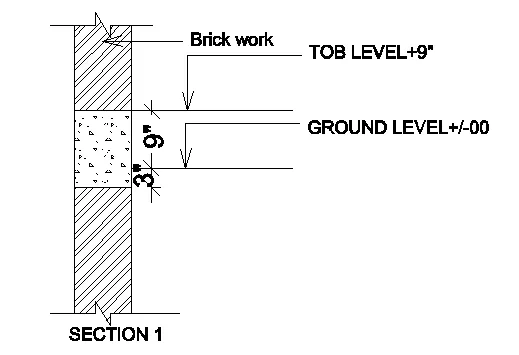
AIM:- TO CREATE A BEAM DETAILS.
COMMAND USED IN FIGURE:-
- line
- limits
- text
- hatch
- trim
- mirror
- offset
PROCEDURE:-
- open autocad and set limits and units.
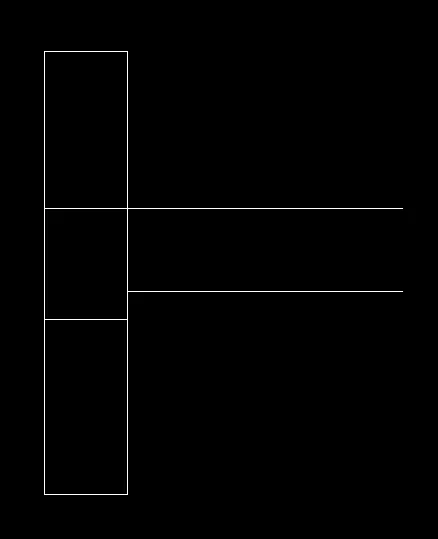
- now take line command and draw line length of 4' vertical and from last point draw line of 9" horizontally .
- with same dimmension complete the rectangle.
- from the upper side leave the distance of 1'5" and draw the line for ground level.
- with that same line give offset of 9" for next line in downword.
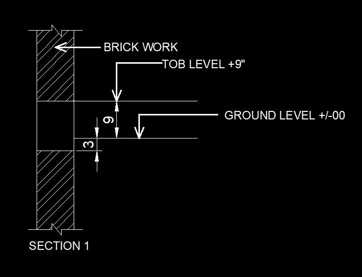
- now using hatch command give various hatch as given in figure.
- now take text command show all mention text in figure.
- using dimmention tool show dimension in figure.
RESULT:- GIVEN DRAWING TEMPLATE IS SUCCESFUL DRAWN IN AUTOCAD.
 .
.