Creation of Column Schedule and Drawing Template using AutoCad
Aim:To draw the given Tables and Diagrams and to enter the Text in to the drawn tables and at required places for the drawn Diagram.
Process:We just use the basic commands to draw the Tables and the Diagram and then we use the Text Commands to enter the Text in the drawn Tables and at required places for the drawn Diagram.
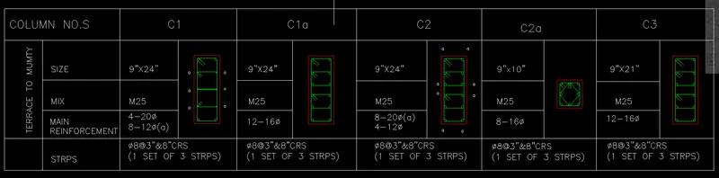
FIGURE 1:COLUMN SCHEDULE
Aim:
To draw the given COLUMN SCHEDULE and to enter the Text in to it.
Process:
We use few Commands to draw the Table and then we use few more Commands to enter the Text in to it.
The Commands which we use are:
- XLINE
- LINE
- TRIM
- TEXT
- CIRCLE
- COPY
- OFFSET
- SCALE
- FILLET
- MOVE
- XLINE:We use this Command in order to form the outer lines of the Table.
- LINE:We use this Command in order to draw the inner lines present in the Table.
- TRIM:We use this Command in order to Trim the extra lines present in the Table.
- TEXT:We use this Command to enter the Text required in the Table.
- CIRCLE:We use this Command to draw the Circles which represent the Steel Bars present in the Column.
- COPY:We use this Command in order to Copy the Column Detailing Figures from outside to the Table.
- OFFSET:We use this Command to Offset the lines such in the Table and in Column Detailing Figures.
- SCALE:We use this Command to Scale the Objects where we draw the Column Detailing Figures of smaller size and scale them to require size.
- FILLET:We use this Command to form the rounded corners in the stirrups along the Steel Bars.
- MOVE:We use this Command in order to move the images along with the words to certain good position to get a good ppearance.
- Initially,we start the process with using the XLINE Command where,we draw a Vertical Line and the Horizontal Line such that the top left corner is formed after trimming the lines using the TRIM Command.
- We have to enter the Text thereafter where we use the Font Style of ROMANS.SHX and we use a Height of 8" and we even Jusify the Text to LEFT.
- We now use the OFFSET Command to make a line from the Top Line at a depth of 10".
- Where using this Line as reference,we type the entire Text present in the Top Header using the mentioned Font Style and Height.
- Where we use the TEXT Command to type the Text and we select the starting point on the above mentioned reference line.
- Here,we use the Text size of 6" for the remaining Text.
- The reference lines are deleted after writing the Text.
- Now,the process is carried out for the Side Header Text.
- And in the same manner,we enter the remaining Text too.
- Multi Line Text Command is used to enter the Text of STIRRUPS and MAIN REINFORCEMENT in the COLUMN SCHEDULE.
- Here,we adjust the given Text as per the Size where we use a Size of 6" and we have to adjust the position of the Text to make sure that the Text appears in the Center and to give a good appearance.
- Now,we impart the Column Figures in to the Table.
- Where instead of drawing the Column Outlines in the Table,we draw it outside and then we Copy it here using COPY Command and then we scale it to require size using the SCALE Command.
- To draw the Column Detailing,we use the given size of the Column in the Table,so as to get a good image.
- So,to for the Column Detailing Figures,we draw the outline of the Column such as 9"x24" for the first one,where this comes as the Concrete Outing,so,we use OFFSET Command to for the internal bars and even to mention the cover of the Column.
- Now,we use the OFFSET Command to get the lines internal where we specify the Offset Distance as 1" which is assumed by us.
- And then,we trim the Lines using the TRIM Command to avoid intersection of the Lines.
- No,initially,we draw the Steel bars present at the corners using the CIRCLE Command and by using the option called TAN TAN RADIUS,where we select the adjacent bars as the Tangents and then we specify the radius of 0.39" as per the given Text.
- And then we have to fillet the bars to given a rounded form along the bars.where we use the FILLET Command and select the bars and give the same radius of 0.39".
- This process is carried for all the 4 corners of the Column.
- Now,we draw the middle bars,for which we draw the vertical and horizontal bars as the reference at certain lengths using the OFFSET Command.
- After this,we can form the internal stirrups.
- Where,when the drawing gets ready,these images can be copied to the necessary location and be scaled to required size where all the images are scaled 3 times the intial ones.
- And this process can be repeated for all the other remaining column detailing figures.
- We can even apply the Layering where the outer line which is of Concrete can be of Layer with the Red Colour and the internal lines which are of steel could be brought up into one layer with Green Colour.
- We even use the MOVE Command to move the Text and the Images to required position to give a good appearance.
Result:
Hence,the given COLUMN SCHEDULE is drawn with the Text and the Diagrams included in it.
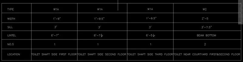
FIGURE 2:WINDOW SCHEDULE
Aim:
To draw the given WINDOW SCHEDULE and to enter the Text in to it.
Process:
We use few Commands to draw the Table and then we use few more Commands to enter the Text in to it.
The Commands which we use are:
- XLINE
- LINE
- TRIM
- TEXT
- OFFSET
- MOVE
- XLINE:We use this Command in order to form the outer lines of the Table.
- LINE:We use this Command in order to draw the inner lines present in the Table.
- TRIM:We use this Command in order to Trim the extra lines present in the Table.
- TEXT:We use this Command to enter the Text required in the Table.
- OFFSET:We use this Command to Offset the lines such in the Table.
- MOVE:We use this Command in order to move the text to certain good position to get a good appearance.
- Initially,we start the process with using the XLINE Command where,we draw a Vertical Line and the Horizontal Line such that the top left corner is formed after trimming the lines using the TRIM Command.
- We have to enter the Text thereafter where we use the Font Style of ROMANS.SHX and we use a Height of 8" and we even Jusify the Text to LEFT.
- We now use the OFFSET Command to make a line from the Top Line at a depth of 10".
- Where using this Line as reference,we type the entire Text present in the Top Header using the mentioned Font Style and Height.
- Where we use the TEXT Command to type the Text and we select the starting point on the above mentioned reference line.
- The reference lines are deleted after writing the Text.
- And one more line is formed using the OFFSET Command at a depth of 2" from the above mentioned Horizontal reference line before deleting the reference line which are the lines to be present in the WINDOW SCHEDULE.
- This process is carried out further carried for the further lines in the WINDOW SCHEDULE.
- After the formation of the WINDOW SCHEDULE and the Text,using the MOVE Command the Text is adjusted to be at centre or at good position to give a better appearance.
Result:
Hence,the given WINDOW SCHEDULE is drawn with the Text included in it.
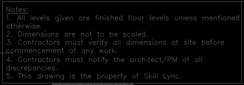
FIGURE 3:DRAWING TEMPLATE
Aim:
To draw the given DRAWING TEMPLATE and to enter the Text in to it.
Process:
We use few Commands to draw the Table and then we use few more Commands to enter the Text in to it.
The Commands which we use are:
- XLINE
- LINE
- TRIM
- TEXT
- OFFSET
- MOVE
- XLINE:We use this Command in order to form the outer lines of the Table.
- LINE:We use this Command in order to draw the inner lines present in the Table.
- TRIM:We use this Command in order to Trim the extra lines present in the Table.
- TEXT:We use this Command to enter the Text required in the Table.
- OFFSET:We use this Command to Offset the lines such in the Table.
- MOVE:We use this Command in order to move the Text to certain good position to get a good appearance.
- Initially,we start the process with using the XLINE Command where,we draw a Vertical Line and the Horizontal Line such that the top left corner is formed after trimming the lines using the TRIM Command.
- We have to enter the Text thereafter where we use the Font Style of ROMANS.SHX and we use a Height of 8" and we even Jusify the Text to LEFT.
- So,now,we use the Multi Line Text Command to write the NOTES.
- Whereafter completing it,we draw the Horizontal Line below it using the OFFSET Command,where in between these horizontal lines,we have to fill the remaining Text forming the Lines.
- So,the lines are formed basing upon the given DRAWING TEMPLATE where the Text is to be entered as given,the references lines are to be deleted leaving the primary lines.
- After filling the Text with the help of TEXT Commands,we adjust the Text with the MOVE Command to certain good positions.

Result:
Hence,the given DRAWING TEMPLATE is drawn with the Text included in it.
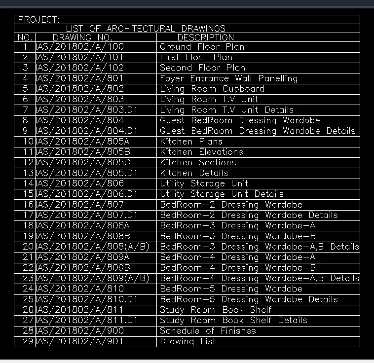
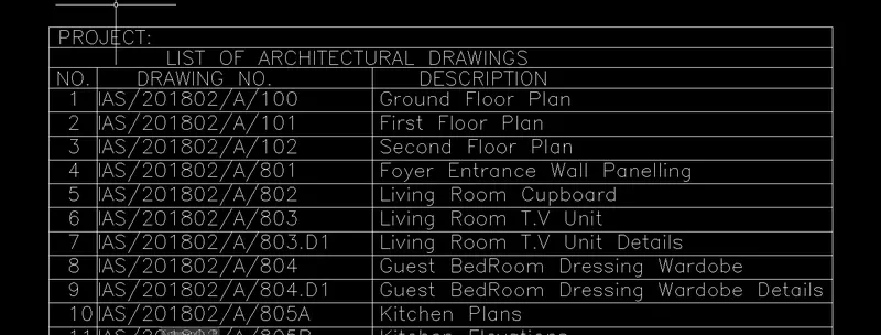
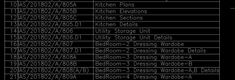
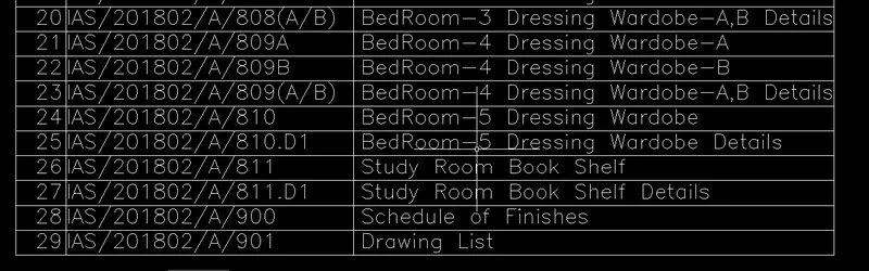
FIGURE 4:DRAWING SCHEDULE
Aim:
To draw the given DRAWING SCHEDULE and to enter the Text in to it.
Process:
We use few Commands to draw the Table and then we use few more Commands to enter the Text in to it.
The Commands which we use are:
- XLINE
- LINE
- TRIM
- TEXT
- OFFSET
- MOVE
- XLINE:We use this Command in order to form the outer lines of the Table.
- LINE:We use this Command in order to draw the inner lines present in the Table.
- TRIM:We use this Command in order to Trim the extra lines present in the Table.
- TEXT:We use this Command to enter the Text required in the Table.
- OFFSET:We use this Command to Offset the lines such in the Table.
- MOVE:We use this Command in order to move the Text to certain good position to get a good appearance.
- Initially,we start the process with using the XLINE Command where,we draw a Vertical Line and the Horizontal Line such that the top left corner is formed after trimming the lines using the TRIM Command.
- We have to enter the Text thereafter where we use the Font Style of ROMANS.SHX and we use a Height of 8" and we even Jusify the Text to LEFT.
- So,now,we use the TEXT Commands to enter the Text in to it.
- Now,we use OFFSET Command to form the horizontal refernce line at a depth of 10" from the top,which therafter used to write the Text and this line is deleted after forming another line with the depth of 2".
- This is done upto the first 3 Lines.
- Where from the 4th line,we use even the Vertical Lines as the reference lines so that the Text in the remaining lines will be aligned as per these lines.
- Where we form a reference line at a depth of 10" from the top and we form the main line at 4" therafter after,which the reference line is deleted.
- Basing upon these vertical and horizontal reference lines,the Text is written and further the references lines are deleted.
- After the entire text in entered the table is formed and the extra lines are trimmed using the TRIM Command.
Result:
Hence,the given DRAWING SCHEDULE is drawn with the Text included in it.
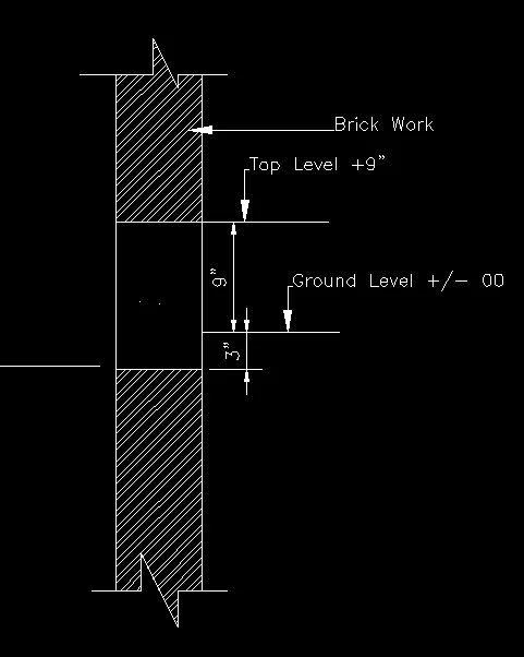
FIGURE 5:BEAM DETAIL
Aim:
To draw the given BEAM DETAIL and to enter the Text in to it.
Process:
We use few Commands to draw the Diagram and then we use few more Commands to enter the Text.
The Commands which we use are:
- LINE
- TEXT
- OFFSET
- HATCH
- LINE:We use this Command in order to draw the lines.
- TEXT:We use this Command to enter the Text required.
- OFFSET:We use this Command to Offset the lines.
- HATCH:We use this Command in order to move the images along with the words to certain good position to get a good ppearance.
- Initially,we draw the Vertical Lines using the LINE Command of required height.
- We Offset this line parallelly at a certain distance using the OFFSET Command.
- Then,we form the vertical lines as required.
- When the 3 segments are formed in the Wall,care is to be taken that the middle segment should be of the height of 12",where 2 horizontal lines are to be projected to the rightwards,to a required distance.
- Once,when this is done,the upper and the bottom segments are to be Hatched using the HATCH Command,where we hatch the respective regions with the BRICKWORK related pattern and the middle segment is to be Hatched with the CONCRETE FILL pattern.
- No,the Text is to be mentoined at the relative places.
- Where,before this the arrows are to placed using the LEADER Options present in the Ribbon.
- Once,when the arrows are formed,the Text is to be entered using the TEXT Command where we specify the starting point on the end of the Leader itself and we give a height of 3" to the font.
- And,finally,the Dimensioning is to be done using the DIMENSION LINEAR Command.
Result:
Hence,the given BEAM DETAIL is drawn and the Text is mentioned where ever required.
Result:Thus,the given SCHEDULES have been draw along with the BEAM DETAIL in the AutoCAD.