Creation of Column Schedule and Drawing Template using AutoCad
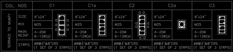
1. Aim: To create a column schedule as shown in figure
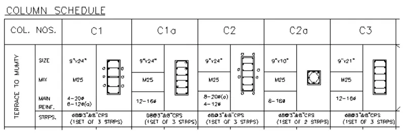
Introduction: Column schedule is drawn using lines and the columns are drawn using rectangle,offset,circle with given specifications.
Procedure:
- Open AutoCAD software
- Start new drawing
- Type REC in command line and click enter
- Specify first corner point
- Specify next corner point or [Area Dimensions Rotation]
- Click on dimensions
- Enter length: 9"
- Enter width: 24"
- Click Enter
- Type offset in command line and click enter
- Specify offset distance: 1"
- Select the object and click inside of it
- Divide it into 4 parts
- Draw circles of 0.5 diameter at all corners
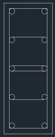
- Copy the objects and make it into 5 parts
- Draw the circles with dimensions at corner points
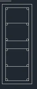
- Again make a copy of it
- Draw the circles at corner points
- Type REC in command line and click enter
- Specify first corner point
- Specify next corner point or [Area Dimensions Rotation]
- Click on dimensions
- Enter length: 9"
- Enter width: 10"
- click enter
- Make offset 1" inside of it and 0.315" inside it
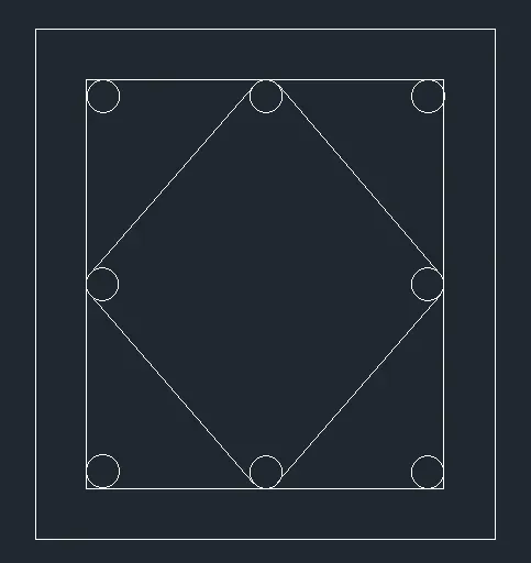
- Type REC in command line and click enter
- Specify first corner point
- Specify next corner point or [Area Dimension Rotation]
- Click on dimensions
- Enter length: 9"
- Enter width: 21"
- Click enter and make it into 5 parts
- Type REC in command line and click enter
- Specify first corner point
- Specify next corner point or [Area Dimension Rotation]
- Click on dimension
- Enter length:810
- Enter width:190
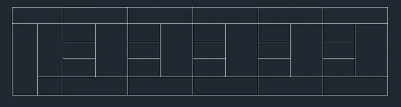
- Click enter
- Draw lines in it as we required for the table
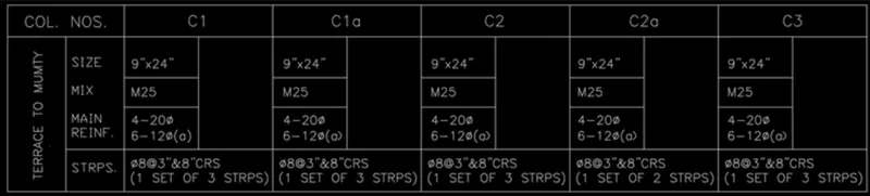
- Enter the data using text command at MC
- Copy the above drawn figures into it
- Move the columns one by one to their respective places
Result: Column schedule is displayed as per the specifications
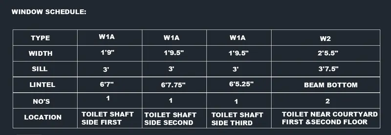
2. Aim: To create a window schedule as shown in figure
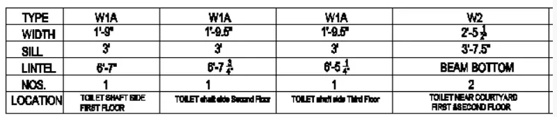
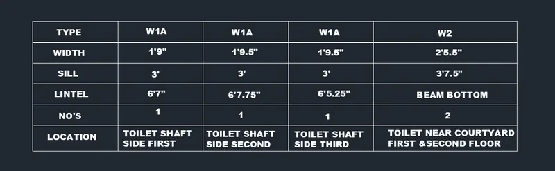
Introduction: Window schedule is created using table and the text is entered with single line text is mentioned type, width, sill, lintel, no's, location for different types of beams
Procedure:
- Open AutoCAD software
- Start new drawing
- Type Table in the command line and click enter
- Enter no of data rows and columns with one header and data
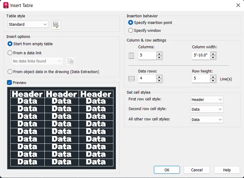
- Table will be displayed and place it where we need
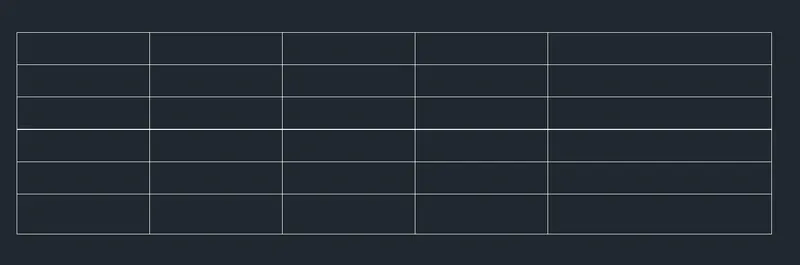
- Using singleline text enter the data in it and place in it centre of the box
- Using text, give the heading window schedule
Result: Window schedule is displayed as per the specifications
3. Aim: To create the drawing template as shown in figure
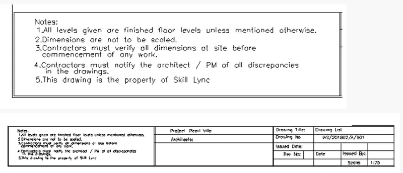
Introduction: Drawing template is created using multiline text, rectangle, offset and line
Procedure:
- Open AutoCAD software
- Start new drawing
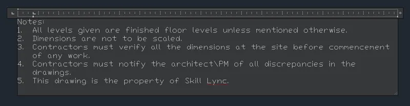
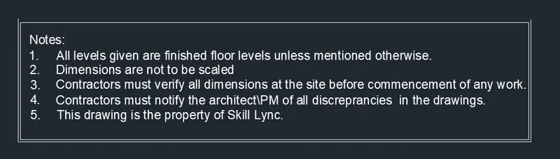
- Type MULTILINE TEXT in command line and click enter

- Specify start point, end point and enter the text in it
- Type REC in the command line and click enter
- Specify first corner point
- Specify next corner point or [Area Dimension Rotation]
- Click on dimensions
- Enter length: 360
- Enter width: 35

- Enter the text using singleline text and place it in the MC of it

Result: Drawing template is displayed as per specifications

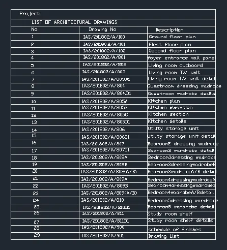
4. Aim: To create the list of drawing schedule as shown in figure
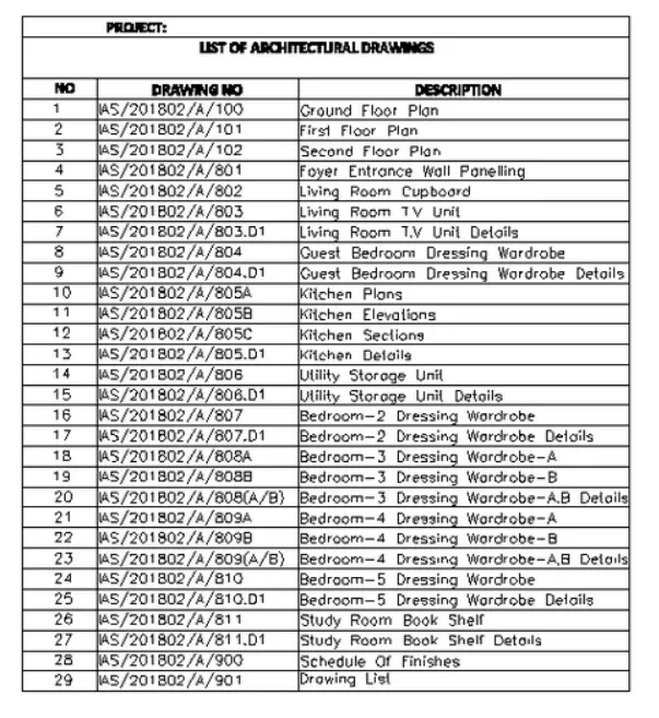
Introduction: Drawing schedule is created using table and text
Procedure:
- Open AutoCAD software
- Start new drawing
- Type TABLE in the command line and click enter
- Enter no.of data rows and columns then click enter
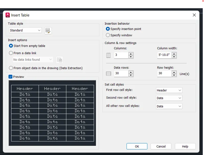
- Place the cursor and click enter

- Enter the text using singleline command and place it in MC
Result: Drawing schedule is displayed as per specifications
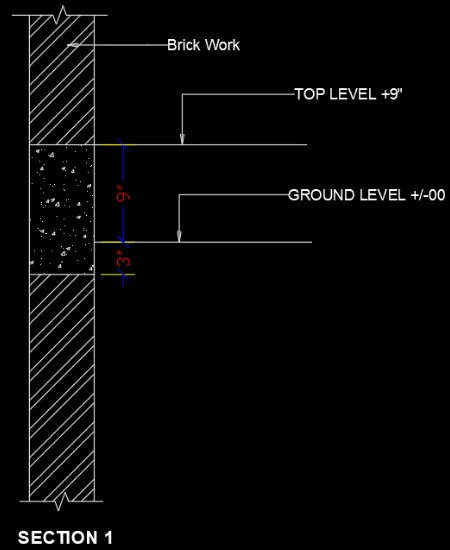
5. Aim: To create the beam detail as shown in figure and provide text for top level and ground level
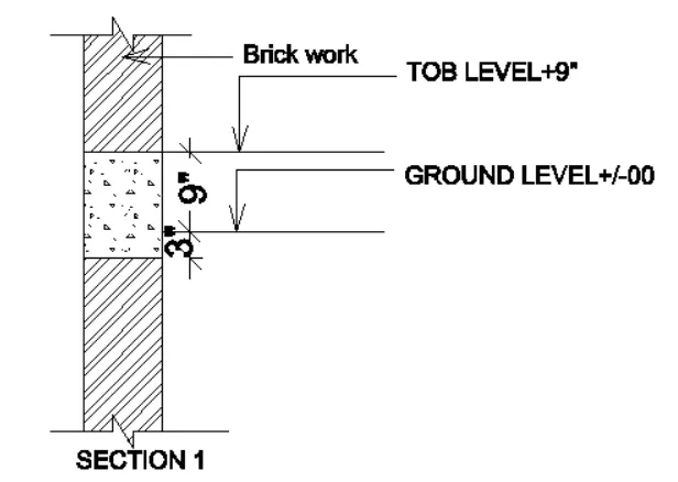
Introduction: Beam details is done with lines, offset and breaklines
Procedure:
- Open AutoCAD software
- Start new drawing
- Type LINE in the command line and click enter
- Specify start point
- Specify second point: 45"
- Type offset in command line and click enter
- Specify offset distance: 6"
- Select the object and click enter
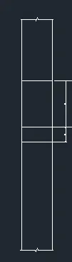
- Type BREAKLINE in the command line and click enter
- Specify start nd end points
- Specify location for break symbol<midpoint>
- Click at the centre
- Repeat it on otherside
- Type hatch in the command line and click enter
- Pick internal point or [Select object Undo Settings]
- click on settings and choose ANS132
- Concrete is hatched on otherside
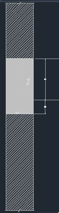
- Give the required labelling using leader and multitext
- Type DIMLINEAR in command line and click enter
- Specify the dimensions
Result: Beam detail is displayed as per the specification
CHALLENGE ACCOMPLISHED