Creation of Column Schedule and Drawing Template using AutoCad
CREATION OF COLUMN SCHEDULE AND DRAWING TEMPLATE USING AUTOCAD.
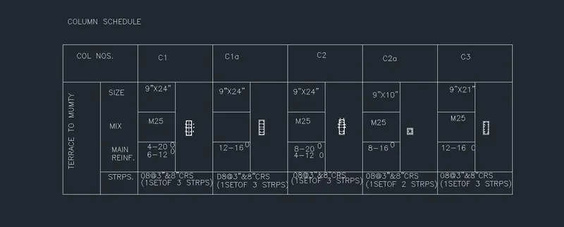
1) COLUMN SCHEDULE:
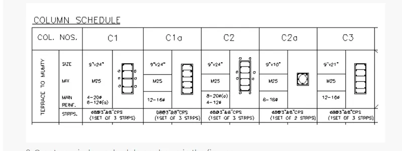
AIM : TO CREATE A COLUMN SCHEDULE WITH THE HELP OF LINES AS SHOWN IN THE FIGURE ABOVE IN AUTOCAD.
PROCEDURE:
STEP 1:
- Type units and select engineering and select precision as 0’-0”.
- Type limits in the command tab. Lower limits is 0’0.0”,0’0.0” and upper limits are 100',100.
- Type Z enter to all and enter A
- Click OK.
STEP 2:
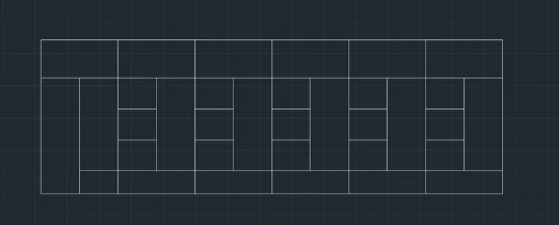
- Select the line tool by entering LINE command in the command tab.
- Specify the first point as 0,0 in the command line.
- Specify the next point as @60’,0’ in the command.
- Specify the next point as @0’,20; in the command.
- Specify the next point as -@60’,0’ in the command.
- Click close on the command line.
- Take the offset command in the command tab.
- Select the top horizontal of the drawing and take offset distance 5’ in the command.
- Again take the offset command in the command tab.
- Select the bottom horizontal of the drawing and take offset distance 3’ in the command.
- Again take the offset command in the command tab.
- Select the top horizontal and take offset distance 4’ in the command and again offset two times.
- Again take the offset command in the command tab.
- Select the left vertical line and take offset distance 5’ and enter inside of the drawing and again 11 more times to offsetted.
- Press Esc to cancel the offset command.
- Select the trim command in the command tab.
- Trim the unwanted lines in the drawing.
- Press Esc to cancel the trim.
STEP 3:
- Enter the DTEXT command in the command tab.
- Specify the start point as required.
- Angle of rotation of the text is 0.
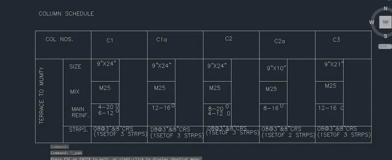
- Enter the name of the table that is column schedule.
STEP 4:
- To draw the columns , type RECTANG in the command line and press enter.
- Specify the first point of the rectangle.
- Enter dimensions .
- Select the length of the rectangle = 9”.
- Select the width of the rectangle = 24”.
- Move the cursor upward to create the rectangle.
- Type offset in the command line in the command tab.
- Enter offset distance 1”.
- Select the rectangle to offset and inside it.

STEP 5:
- Turn on ORTHO mode.
- Draw a line connecting the center of the rectangle.
- Type of DIV and press ENTER.
- Select the center line drawn.
- Specify the number of segments as 4 and press enter.
- Through the divided points draw lines horizontally.
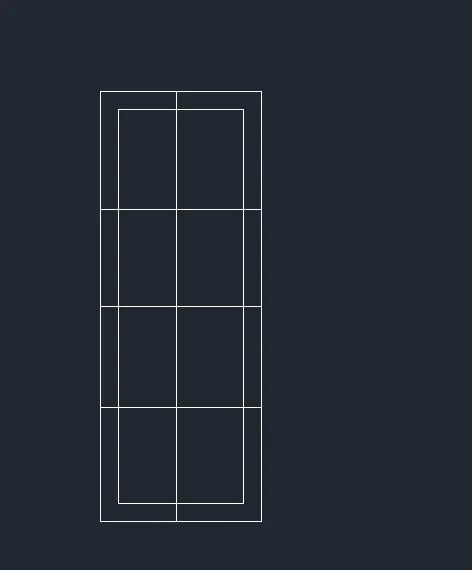
STEP 6:
- Now, create an offset of the inside rectangle as 5”.
- Select the circle command as radius of 0.5” and place it at the respective places.
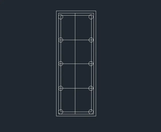
STEP 7:
- Delete the unwanted lines using the trim command in the command tab.
- And trim the last made rectangle.
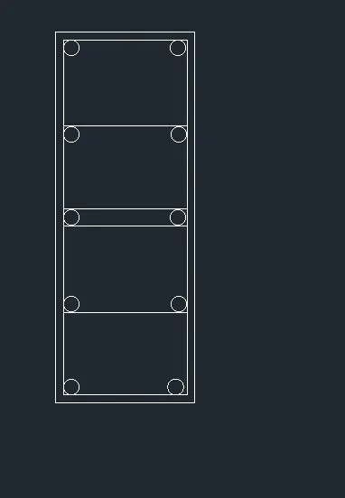
STEP 8:
- Now, apply the hatch and select the hatch command in the command tab.
- And fill the circles with hatches.
- Type DTEXT command and write text.
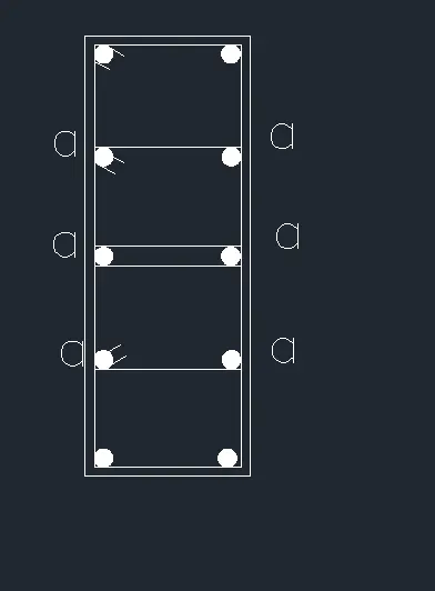
STEP 9:
- Similarly the other 4 columns are created. The basic steps remain the same as above and there is only change in dimensions.
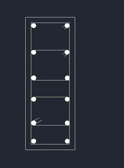
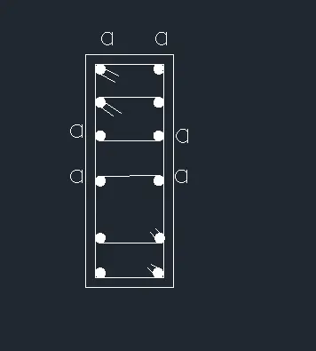

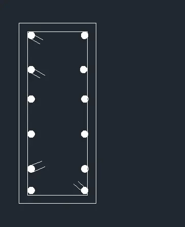
STEP 10:
- Enter CO command in the command line.
- Select the column section and place it 4 times in the table created.
=======================================================================================================================
2) WINDOW SCHEDULE:
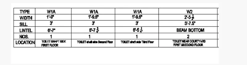
AIM : TO CREATE THE WINDOW SCHEDULE WITH THE HELP OF TABLE AND TEXT COMMAND AS SHOWN IN THE FIGURE ABOVE IN AUTOCAD.
PROCEDURE:
STEP 1:
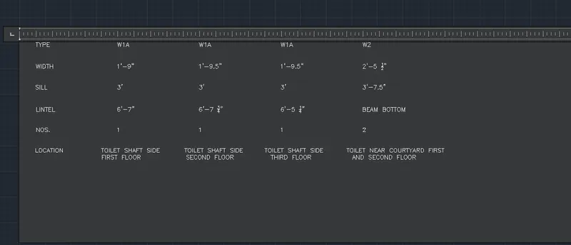
- Select the annotation tab and select the multi lines text.
- Specify the first and opposite corner and then start typing.
- Tab key in keyboard can be used for equal spacing of words.
STEP 2:
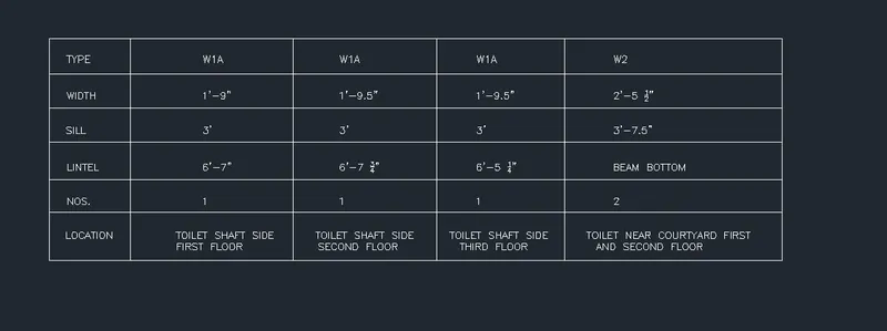
- Now using the line command boundaries are given to the window schedule.
=======================================================================================================================
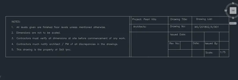
3) DRAWING TEMPLATE:
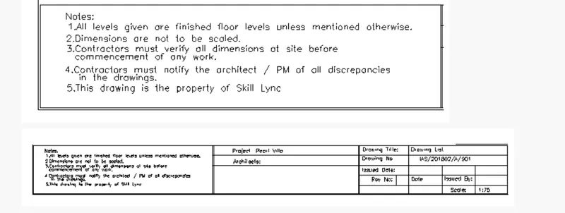
AIM: TO CREATE THE DRAWING TEMPLATE WITH THE HELP OF ANNOTATION TAB AND DTEXT COMMAND.
PROCEDURE:
STEP 1:
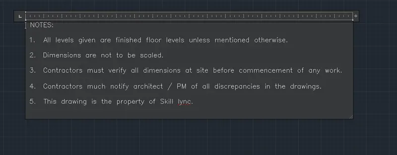
- Select the annotation tab and select multi lines text.
- Specify the first and opposite corner and then start typing.
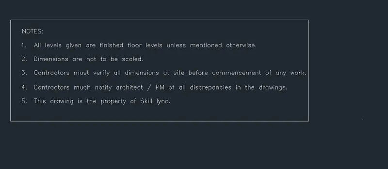
STEP 2:
- Now using the line command a boundary was given to it.
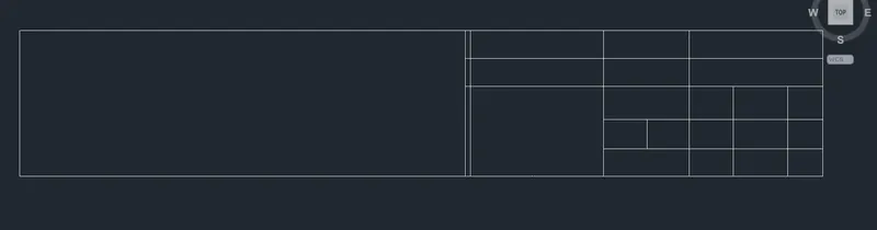
STEP 3:
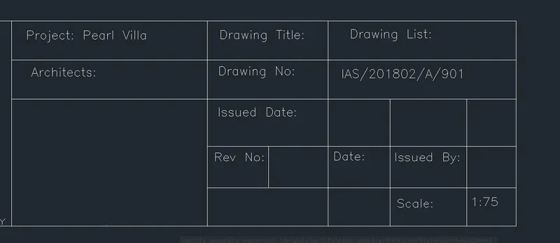
- A table was created using the line and rectangle tools .
- Now using the MTEXT command the table was filled up and the resultant image of the drawing template is as given.
RESULT:
=======================================================================================================================
4) LIST OF DRAWING SCHEDULE:
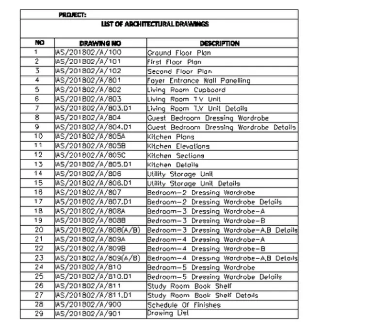
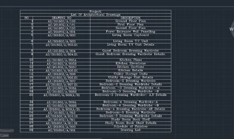
AIM: TO CREATE THE LIST OF DRAWING SCHEDULE WITH THE HELP OF TABLE AND TEXT COMMAND AS SHOWN IN THE FIGURE ABOVE IN AUTOCAD.
PROCEDURE:
STEP 1:
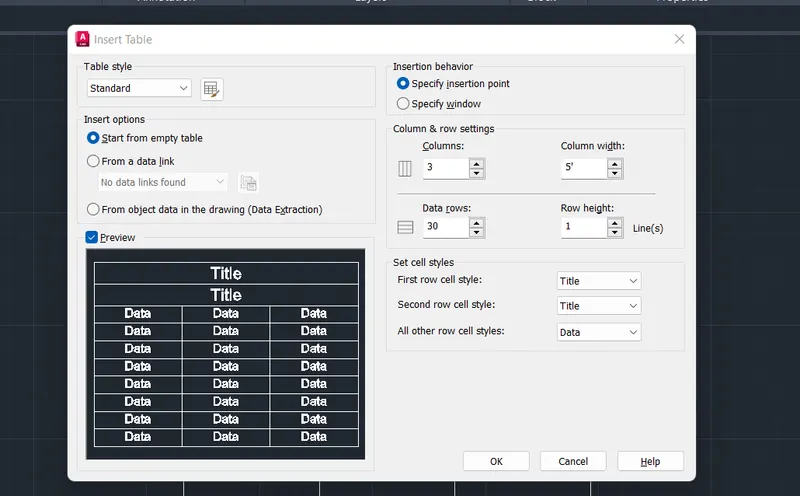
- Enter table command in the command tab.
- In the table command, number of rows = 30 and row height = 1. Number of columns = 3 and column width = 5’.
- Click ok.
STEP 2:
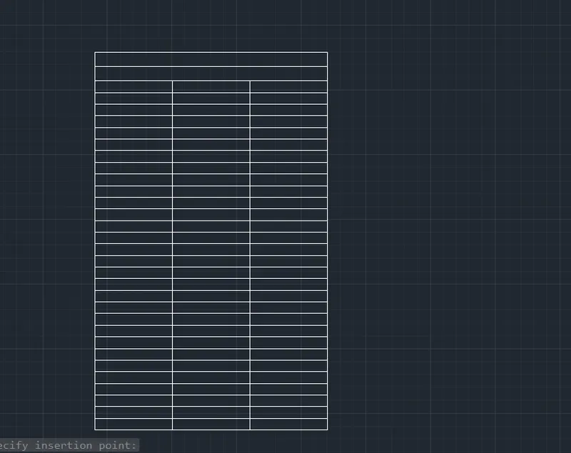
- Create a table according to the table command .
- And adjust the sizes of rows and columns.
STEP 3:
- Enter ST command in the command tab.
- Select the font name as romans.shx; text height 10’.
- Enter mtext command in the command tab.
- Specify the start point as required.
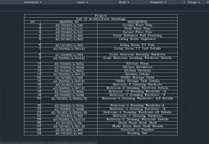
RESULT:
=======================================================================================================================
5) BEAM DETAIL:
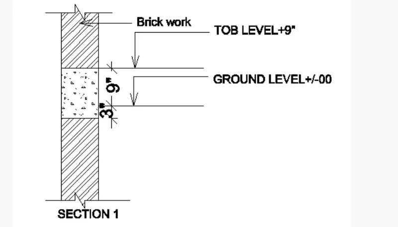
AIM: TO CREATE THE BEAM DETAIL WITH THE HELP OF LINE COMMAND USING AUTOCAD.
PROCEDURE:
STEP 1:
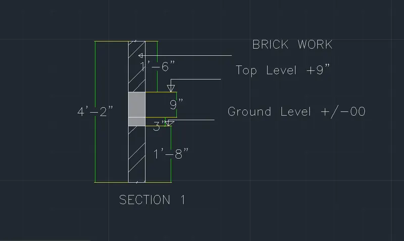
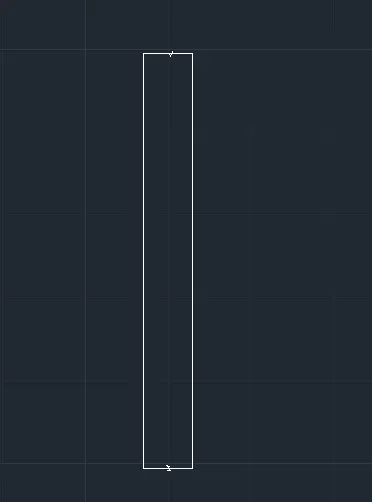
- According to the dimension using the line command the following image was created.
- By using the breakline command, make a breakline at the top and bottom.
STEP 2:
- Take the offset command in the command tab.
- Give offset distance as top 1’6” and again offset distance bottom as 1’8.0”.
- Again take the offset command in the command tab.
- Give offset distance as previous line as 3.0”and again take offset distance as previous line as 9.0”.
- Select hatch command in the command tab.
- Now giving the hatching of brickwork and concrete.
- Then given the dimension.
- Type all the necessary text by using single line text or multi line text.