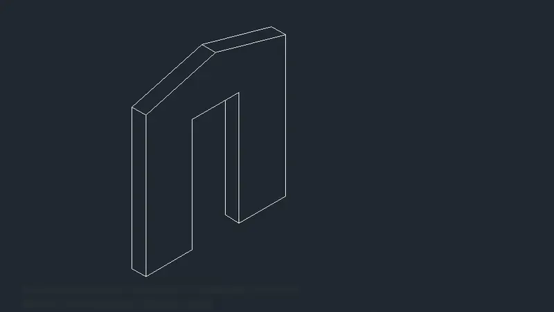
Creating a Floor plan, Footing detail and Isometric view using AutoCad
QUESTION 1 : Creating a floor plan, footing detail and isometric view using autocad:
C.S OF LOAD BEARING WALL OVER SPREAD FOOTING:
AIM: To draw the cross - section of a load bearing wall over spread footing.
INTRODUCTION:
The desired cross section is created in autocad using primarily the line and rectangle tools. The procedure of drawing is explained in detail with a diagram of each step and the final result is given.
PROCEDURE:
STEP 1:
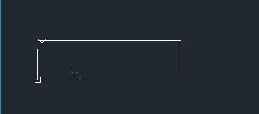
- Select the rectangle tool by entering RECTANG command in the command tab.
- Select the first point as 0,0 in the command line.
- Select the dimension options in the command line.
- Specify the length of the rectangle as 0.90 in the command line.
- Specify the width of the rectangle as 0.25 in the command line.
- Move the cursor to the +ve xy quadrant and click enter.
STEP 2:
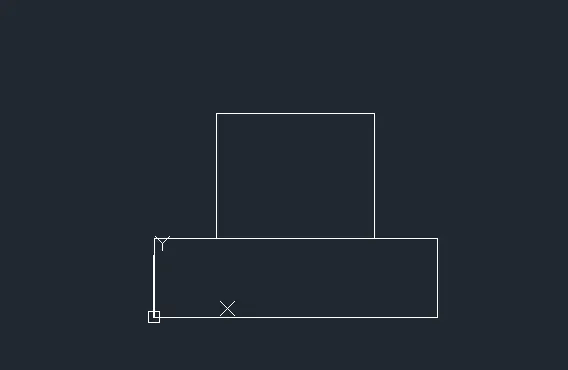
- Select the rectangle tool by entering RECTANG command in the command tab.
- Select the first point as 0.20,0.25 in the command line.
- Select the dimension options in the command line.
- Specify the length of the rectangle as 0.50 in the command line.
- Specify the width of the rectangle as 0.40 in the command line.
- Move the cursor to the +ve xy quadrant and click enter.
STEP 3:
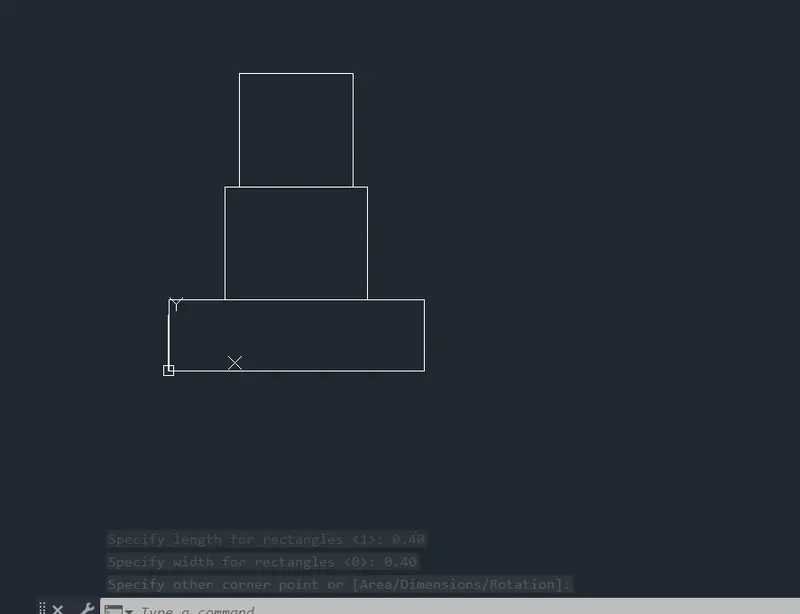
- Select the rectangle tool by entering RECTANG command in the command tab.
- Select the first point as 0.25,0.65in the command line.
- Select the dimension options in the command line.
- Specify the length of the rectangle as 0.40 in the command line.
- Specify the width of the rectangle as 0.40 in the command line.
- Move the cursor to the +ve xy quadrant and click enter.
STEP 4:
- Select the rectangle tool by entering RECTANG command in the command tab.
- Select the first point as 0.30,1.05 in the command line.
- Select the dimension options in the command line.
- Specify the length of the rectangle as 0.30 in the command line.
- Specify the width of the rectangle as 0.60 in the command line.
- Move the cursor to the +ve xy quadrant and click enter.
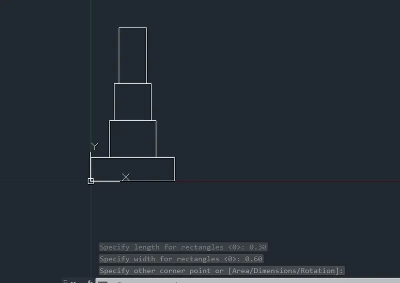
STEP 5:
- Select the rectangle tool by entering RECTANG command in the command tab.
- Select the first point as 0.30,1.65 in the command line.
- Select the dimension options in the command line.
- Specify the length of the rectangle as 0.30 in the command line.
- Specify the width of the rectangle as 0.05 in the command line.
- Move the cursor to the +ve xy quadrant and click enter.
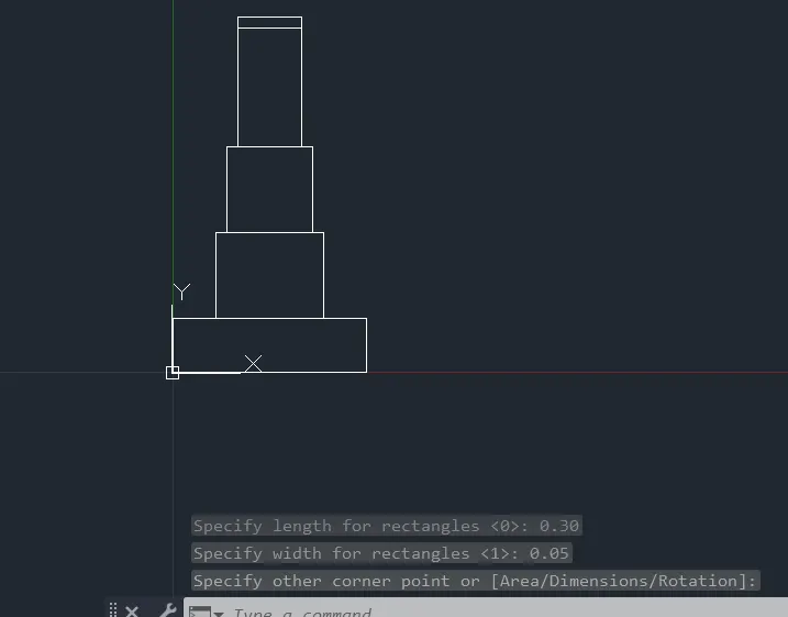
STEP 6:
- Select the rectangle tool by entering RECTANG command in the command tab.
- Select the first point as 0.30,1.70 in the command line.
- Select the dimension options in the command line.
- Specify the length of the rectangle as 0.30 in the command line.
- Specify the width of the rectangle as 1.00 in the command line.
- Move the cursor to the +ve xy quadrant and click enter.
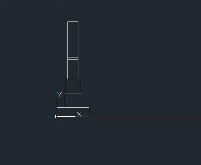
STEP 7:
- Select the rectangle tool by entering RECTANG command in the command tab.
- Select the first point as 0.25,1.05 in the command line.
- Select the dimension options in the command line.
- Specify the length of the rectangle as 1.15 in the command line.
- Specify the width of the rectangle as 0.15 in the command line.
- Move the cursor towards the left and click ENTER.
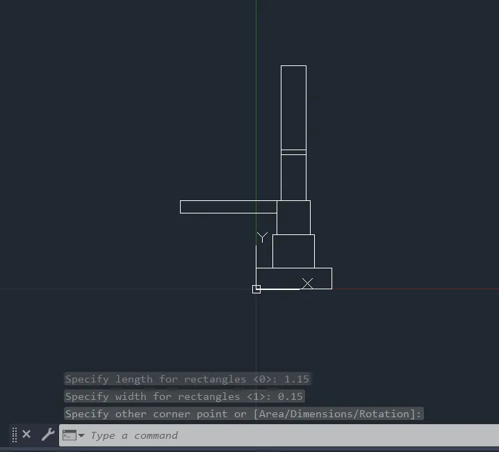
STEP 8:
- Select the line tool by entering LINE command in the command tab.
- Specify the first point as -0.60, 1.05 in the command line.
- Specify the coordinate of the next point as @ 0,0.15 in the command line.
- Specify the coordinate of the next point as @ 0.30,0 in the command line.
- Specify the coordinate of the next point as @ 0,0.15 in the command line.
- Specify the coordinate of the next point as @ 0.30,0 in the command line.
- Specify the coordinate of the next point as @ 0,0.15 in the command line.
- Specify the coordinate of the next point as @ 0.30,0 in the command line.
- Press Esc to cancel the line command.
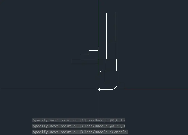
STEP 9:
- Select the trim tool by entering TR command in the command tab.
- Press ENTER.
- Select edge option and click on NO EXTEND.
- Click on the line between the second and third rectangle.
- Press Esc to cancel the trim command.
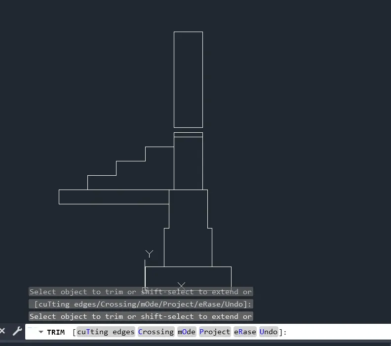
STEP 10:
- Enter DST command in the command tab to open the dimension style manager dialog box.
- Click on the modify tab.
- Under the lines option change the color of the dimensions and extensions line.
- Under the symbols and arrows option change the arrow size to 0.05.
- Under the text option change the text height to 0.05.
- Click ok. Then click on set current and close the dialog box.
- Select the dimension tool by entering DIM in the command line.
- Select the first point and second point of the object to be measured, then drag the dimension line to the desired location. Repeat for all the objects to be measured.
- Enter TEXT command in the command line.
- Specify the start point of text as required.
- Specify height of text as 0.1.
- Specify angle of rotation of text 0.00.
- Enter the name of the drawing .
- Click enter and press Esc.
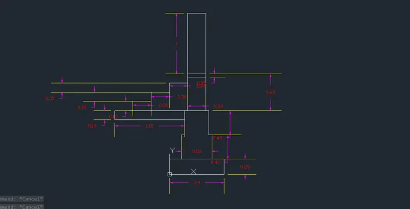
---------------------------------------------------------------------------------------------------------------------------
QUESTION 2 : C.S OF ISOLATED FOOTING:
AIM: To draw the cross section of an isolated footing.
INTRODUCTION:
The desired cross section is created in autocad using primarily the line tool. The procedure of drawing is explained in detail with a diagram of each step and the final result is given.
PROCEDURE:
STEP 1:
- Select the line tool by entering line command in the command tab.
- Specify the first point as 0,0 in the command line.
- Specify the coordinate of the next point as@ 1.00,0 in the command line.
- Specify the coordinate of the next point as @ 0,0.15 in the command line.
- Specify the coordinate of the next point as @ -0.38,0.25 in the command line.
- Specify the coordinate of the next point as @ 0,1.60 in the command line.
- Specify the coordinate of the next point as @ -0.24,0 in the command line.
- Specify the coordinate of the next point as @ 0,-1.60 in the command line.
- Specify the coordinate of the next point as @ -0.38,-0.25 in the command line.
- Click close on the command line.
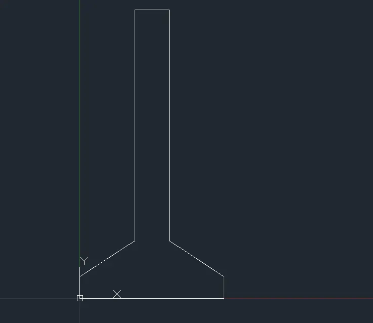
STEP 2:
- Select the line tool by entering LINE command in the command tab.
- Specify the first point as 0.42, 2.00 in the command line.
- Specify the coordinate of the next point as @ 0,-1.96 in the command line.
- Specify the coordinate of the next point as @ -0.38,0 in the command line.
- Specify the coordinate of the next point as @ 0,0.04 in the command line.
- Press Esc to cancel the line command.
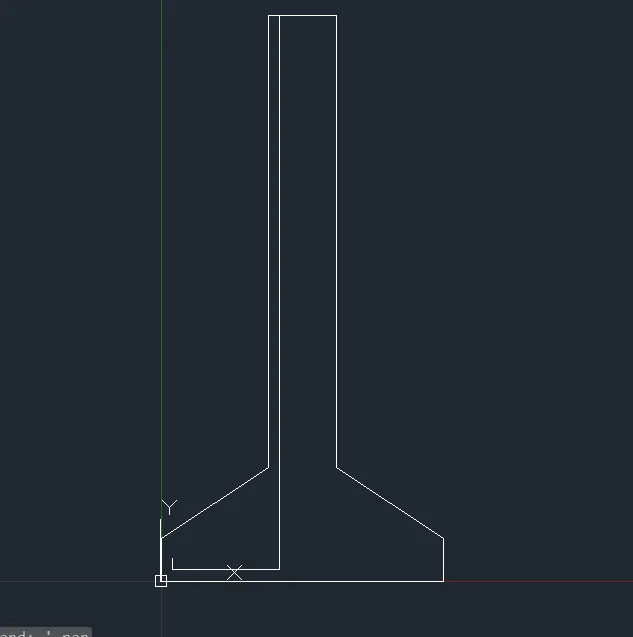
STEP 3:
- Select the mirror tool by entering MIRROR command in the command tab.
- Select the object to mirror that is the object drawn in step 2 and click ENTER.
- Select the first point of the mirror line.
- Select the second point of the mirror line.
- Click NO in the erase source object.
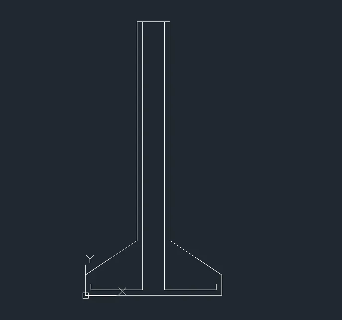
STEP 4 :
- Select the offset tool by entering OFFSET command in the command tab.
- Enter 0.20 as offset distance in the command line.
- Select the top most line of the footing drawing.
- Specify the point on side to offset.
- Repeat the same process for 8 more times.
- Press Esc to cancel the offset command.
- Select the trim tool by entering TR command in the command tab.
- Press ENTER.
- Select the edge option and click NO EXTEND.
- Select the edges of the offset lines having a distance of 0.20.
- Press Esc to cancel the trim command.
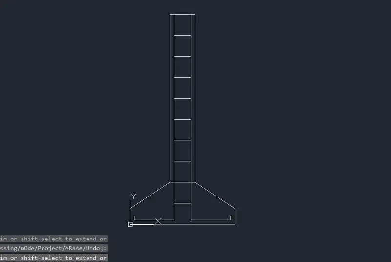
STEP 5:
- Enter DST command in the command tab to open the dimension style manager dialog box.
- Click on the modify tab.
- Under the lines option change the color of the dimensions and extensions line.
- Under the symbols and arrows option change the arrow size to 0.05.
- Under the text option change the text height to 0.05.
- Click ok. Then click on set current and close the dialog box.
- Select the dimension tool by entering DIM in the command line.
- Select the first point and second point of the object to be measured, then drag the dimension line to the desired location. Repeat for all the objects to be measured.
- Enter TEXT command in the command line.
- Specify the start point of text as required.
- Specify height of text as 0.1.
- Specify angle of rotation of text 0.00.
- Enter the name of the drawing .
- Click enter and press Esc.
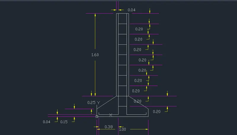
---------------------------------------------------------------------------------------------------------------------------
QUESTION 3 : LINE DIAGRAM OF A TWO ROOM BUILDING:
AIM: TO DRAW THE LINE DIAGRAM OF A TWO ROOM BUILDING:
INTRODUCTION:
The desired diagram is created in autocad using primarily the line tool. The procedure of drawing is explained in detail with a diagram of each step and the final result is given.
PROCEDURE:
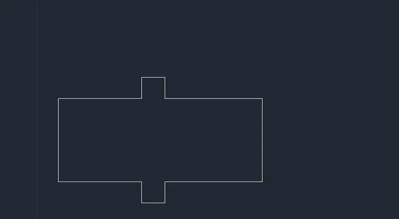
STEP 1:
- Select the line tool by entering LINE command in the command tab.
- Keep the ORTHO mode on.
- Specify the first point as 0,0 in the common dline.
- Specify the next point as 4.20, pointing the cursor toward the +ve x direction.
- Specify the next point as 3.60 pointing the cursor toward the +ve y direction.
- Specify the next point as 4.20 pointing the cursor toward the -ve x direction.
- Specify the next point as 0.90 pointing the cursor toward the +ve y direction.
- Specify the next point as 1.00 pointing the cursor toward the -ve x direction.
- Specify the next point as 0.90 pointing the cursor toward the -ve y direction.
- Specify the next point as 3.60 pointing the cursor toward the -ve x direction.
- Specify the next point as 3.60 pointing the cursor toward the -ve y direction.
- Specify the next point as 3,60 pointing the cursor toward the +ve x direction.
- Specify the next point as 0.90 pointing the cursor toward the -ve y direction.
- Specify the next point as 1.00 pointing the cursor toward the +ve x direction.
- Specify the next point as 0.90 pointing the cursor toward the +ve y direction.
- Click close on the command line.
STEP 2:
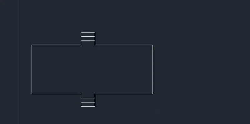
- Select the offset tool by entering OFFSET command in the command tab.
- Enter 0.30 as offset distance in the command line.
- Select the line of length 1.00, for the stairs at the north of the plan.
- Specify the point on side to offset.
- Repeat the same process for both the stairs.
- Press Esc to cancel the OFFSET command.
STEP 3:
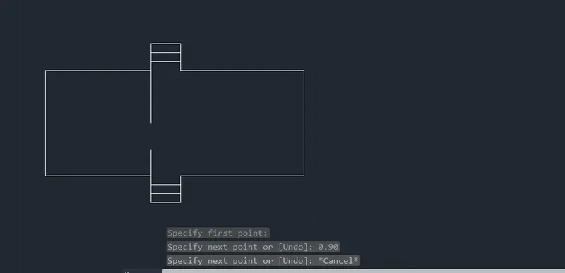
- Select the line tool by entering LINE command in the command tab.
- To draw the partition wall, specify the first point at the corner of the stairs in the north direction.
- Specify the first point as 1.80, pointing the cursor toward the -ve y direction.
- Press Esc to cancel the line command.
- Again select the line tool by entering line command in the command tab.
- Specify the first point at the corner of the stairs at the bottom of the diagram.
- Specify the next point as 0.90 pointing the cursor toward the +ve y direction.
- Press Esc to cancel the line command.
STEP 4:
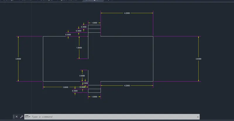
- Enter DST command in the command tab to open the dimension style manager dialog box.
- Click on the modify tab.
- Under the lines option change the color of the dimensions and extensions line.
- Under the symbols and arrows option change the arrow size to 0.10.
- Under the text option change the text height to 0.10.
- Click ok. Then click on set current and close the dialog box.
- Select the dimension tool by entering DIM in the command line.
- Select the first point and second point of the object to be measured, then drag the dimension line to the desired location. Repeat for all the objects to be measured.
- Enter TEXT command in the command line.
- Specify the start point of text as required.
- Specify height of text as 0.15.
- Specify angle of rotation of text 0.00.
- Click enter and press Esc.
---------------------------------------------------------------------------------------------------------------------------
QUESTION 4 : C.S OF LOAD BEARING WALL SHOWING FOUNDATION DETAILS:
AIM : To draw the cross section of a load bearing wall showing foundation details.
INTRODUCTION:
The desired cross section is created in autocad using primarily the line tool. The procedure of drawing is explained in detail with a diagram of each step and the final result is given.
PROCEDURE:
STEP 1:
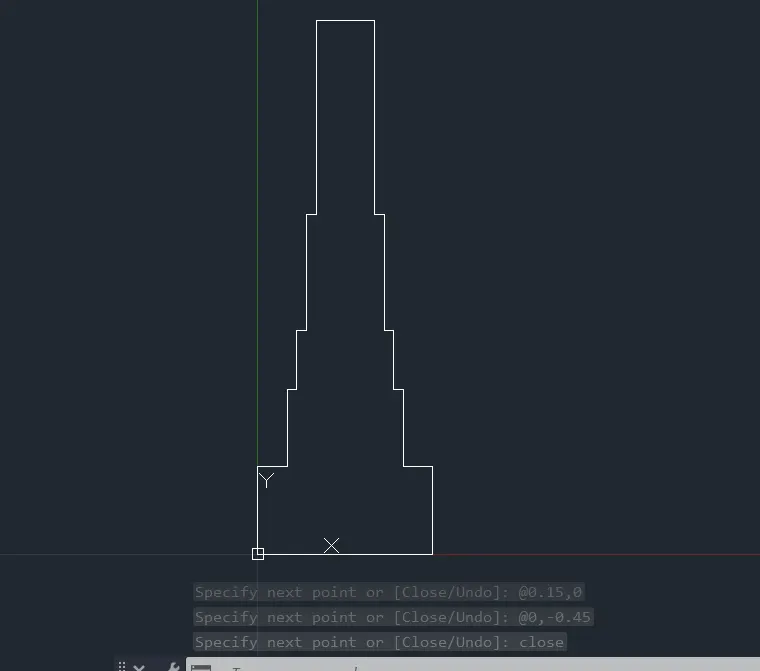
- Select the line tool by entering line command in the command tab.
- Specify the first point as 0,0 in the command line.
- Specify the next point as @0, 0.45 in the command line.
- Specify the next point as @ 0.15,0 in the command line.
- Specify the next point as @0,0.40 in the command line.
- Specify the next point as @ 0.05,0 in the command line.
- Specify the next point as @ 0,0.30 in the command line.
- Specify the next point as @ 0.05,0 in the command line.
- Specify the next point as @ 0,0.60 in the command line.
- Specify the next point as @ 0.05,0 in the command line.
- Specify the next point as @ 0,1 in the command line.
- Specify the next point as @ 0.30, 0 in the command line.
- Specify the next point as @ 0,-1 in the command line.
- Specify the next point as @ 0.05,0 in the command line.
- Specify the next point as @ 0,-0.60 in the command line,
- Specify the next point as @ 0.05,0 in the command line.
- Specify the next point as @ 0,-0.30 in the command line.
- Specify the next point as @ 0.05, 0 in the command line.
- Specify the next point as @ 0,-0.40 in the command line.
- Specify the next point as @ 0.15 ,0 in the command line.
- Specify the next point as @ 0,-0.45 in the command line.
- ENTER close on the command line.
STEP 2:
- Enter DST command in the command tab to open the dimension style manager dialog box.
- Click on the modify tab.
- Under the lines option change the color of the dimensions and extensions line.
- Under the symbols and arrows option change the arrow size to 0.05.
- Under the text option change the text height to 0.05.
- Click ok. Then click on set current and close the dialog box.
- Select the dimension tool by entering DIM in the command line.
- Select the first point and second point of the object to be measured, then drag the dimension line to the desired location. Repeat for all the objects to be measured.
- Enter TEXT command in the command line.
- Specify the start point of text as required.
- Specify height of text as 0.1.
- Specify angle of rotation of text 0.00.
- Enter the name of the drawing .
- Click enter and press Esc.
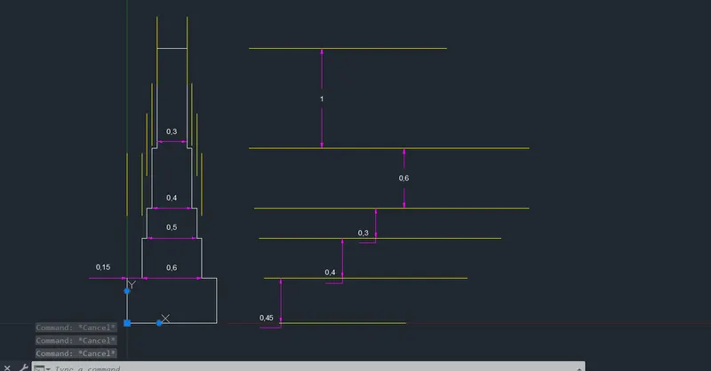
RESULT :
---------------------------------------------------------------------------------------------------------------------------
QUESTION 5 : ISOMETRIC VIEW OF STEPS:
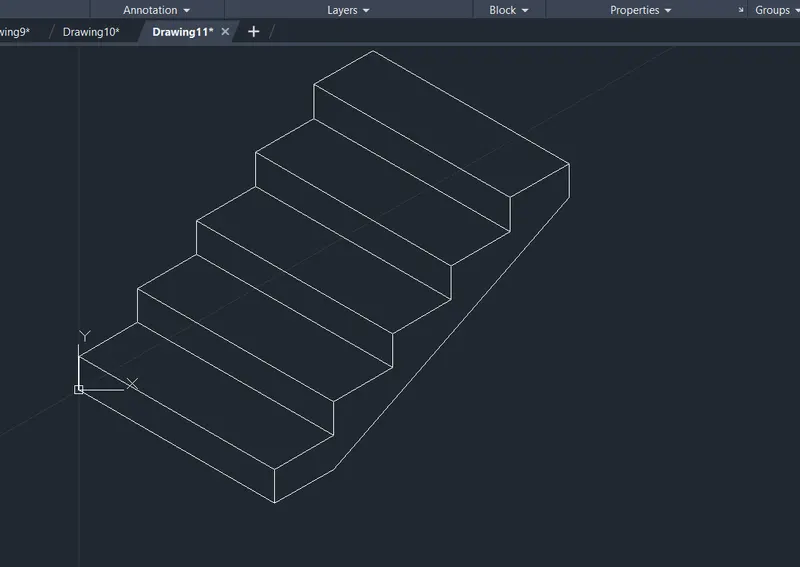
AIM: TO DRAW THE ISOMETRIC VIEW OF STEP
INTRODUCTION:
The desired isometric view of steps is created in autocad using primarily the line tool. The procedure of drawing is explained in detail with a diagram of each step and the final result is given.
PROCEDURE:
STEP 1:
- Turn on the isometric drafting.
- Select isoplane left.
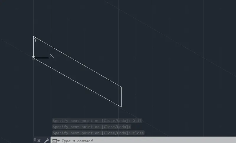
- Select the line tool by entering LINE command in the command tab.
- Keep ortho mode on.
- Specify the first point as 0,0 in the command line.
- Specify the next point as 1.00 pointing the cursor toward the right direction.
- Specify the next point as 0.15 pointing the cursor toward the upward direction.
- Specify the next point as 1.00 pointing the cursor toward the left direction.
- Specify the next point as 0.15 pointing the cursor toward the downward direction.
- Click close on the command line.
Step 2:
- Select isoplane right from isometric drafting dropdown list.
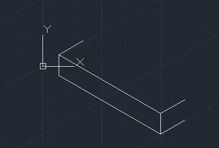
- Select the line tool by entering LINE command in the command tab.
- Keep ortho mode on.
- Specify the first point as the top corner of the above object.
- Specify the next point as 0.30 , pointing the cursor toward the right direction.
- Press Esc to cancel the line command line.
- Specify the copy tool by entering CO command in the command tab.
- Select the line of length 0.30.
- Specify the base point as the left top corner of the previous drawing.
- Copy the line at a distance of 1.00 from the basepoint.
- Press Esc to cancel the copy command.
- Again select the copy tool.
- Select the line 0.30 length copied previously.
- Specify the basepoint at the right top corner of the diagram in the former step.
- Copy it at a distance of 0.15 downward from the base point.
- Press Esc to cancel the line command.
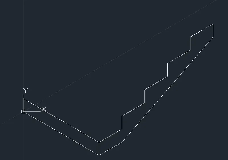
STEP 3:
- Specify the first point isoplane top 0.3 enter.
- Specify the next point isoplane right 0.15 enter.
- Specify the next point 0.15 enter.
- Specify the next point 0.3 enter.
- Specify the next point 0.15 enter.
- Specify the next point 0.3 enter.
- Specify the next point 0.15 enter.
- Specify the next point 0.3 enter.
- Specify the next point 0.15 enter.
- Specify the next point 0.3 enter.
- Select the line tool by entering the LINE command enter.
- Specify the first point 0.3.
- Press Esc to cancel the line command.
STEP 4:
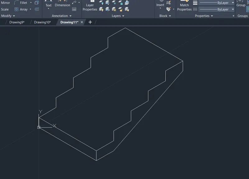
- Select the line entering LINE command in the command tab.
- Specify the first point 0.3 enter.
- Specify the next point 0.15 enter.
- Specify the next point 0.3 enter.
- Specify the next point 0.15 enter.
- Specify the next point 0.3 enter.
- Specify the next point 0.15 enter.
- Specify the next point 0.3 enter.
- Specify the next point 0.15 enter.
- Specify the next point 0.3 enter.
- Press Esc to cancel the line command.
STEP 5:
- Select the copy tool by entering co command in the command tab.
- Select the entire figure created in the above two steps except the line of length 0.3 at the bottom right portion of the stair step.
- Specify the basepoint as the bottom left corner of the step.
- Copy the entire to the top left corner of the step.
- Repeat the same for three more times to get the desired number of steps.
- Press Esc to cancel the copy command.
---------------------------------------------------------------------------------------------------------------------------
QUESTION 6 : ISOMETRIC VIEW OF GABLE WALL:
AIM : TO DRAW THE ISOMETRIC VIEW OF GABLE WALL.
INTRODUCTION:
The desired isometric view of the gable wall is created in autocad, primarily the line tool. The procedure of drawing is explained in detail with a diagram of each step and the final result is given.
PROCEDURE:
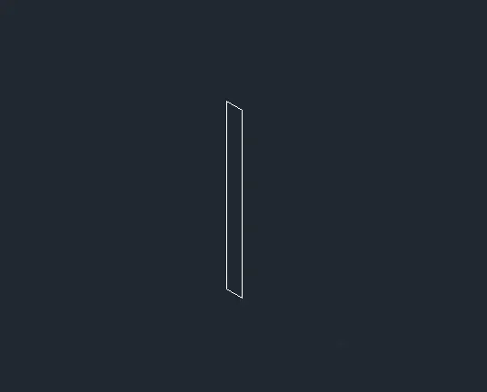
STEP 1:
- Turn on the isometric drafting.
- Select isoplane left.
- Select the line tool by entering LINE command in the command tab.
- Select the first point as 0,0 in the command line.
- Select the next point as 3.00 pointing the cursor towards the upward direction.
- Specify the next point as 0.3 pointing the cursor towards the left direction.
- Specify the next point as 3.00 pointing the cursor towards the downward direction.
- Click close on the command line.
STEP 2:
- Select isoplane right from isometric drafting.
- Select the line tool by entering LINE command in the command tab.
- Keep ortho mode on.
- Specify the first point as the top right corner of the above object.
- Specify the next point as 3.00 pointing the cursors towards the right direction.
- Specify the next point as 3.00 pointing the cursors towards the downward direction.
- Specify the next point as 1.00 pointing the cursors towards the left direction.
- Specify the next point as 2.42 pointing the cursors towards the upward direction.
- Specify the next point as 1.00 pointing the cursors towards the left direction.
- Specify the next point as 2.42 pointing the cursors towards the downward direction.
- Specify the next point as 1.00 pointing the cursors towards the left direction.
- Press Esc to cancel the line command.

STEP 3:
- Select isoplane left from isometric drafting.
- keep ortho mode on.
- Select the line tool by entering LINE command in the command tab.
- Specify the first point at the corner of the door opening.
- Specify the next point as 0,30 pointing the cursor towards the left direction.
- Specify the next point as 2.12 pointing the cursor towards the upward direction.
- Press Esc to cancel the line command.
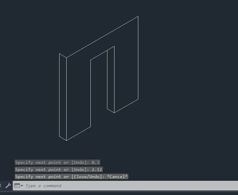
STEP 4:
- Select isoplane right from isometric drafting.
- Keep ortho mode on.
- Select the line tool by entering LINE command in the command tab.
- Specify the first point at the midpoint of the top line.
- Specify the next point as 1.00 pointing the cursor towards the upward direction.
- Draw a line to join the top of the top left corner of the wall.
- Press Esc to cancel the line command.
- Select the line tool by entering LINE command in the command tab and join the top to the corner of the wall.
- Press Esc to cancel the line command.
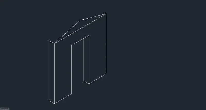
STEP 5:
- Select the copy tool by entering CO command in the command tab.
- Select both the lines of the mount.
- Specify the basepoint as the top left corner of the wall.
- Copy the lines of the mount to the adjacent top left corner of the wall.
- Press Esc to cancel the copy command.
- Select the line tool by entering LINE command in the command tab.
- Join the midpoint from the front face of the mount to the midpoint of the back face of the mount.
- Press Esc to cancel the line command.
- Select the line tool by entering LINE command in the command tab.
- Join the remaining top right corner of the wall.
- Press Esc to cancel the line command.