Creation of Column Schedule and Drawing Template using AutoCad
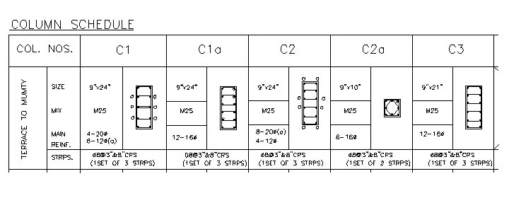
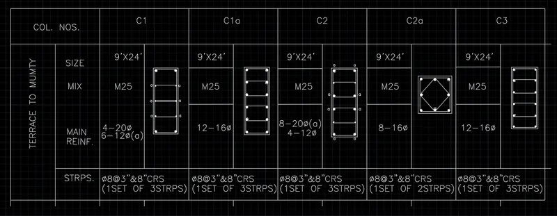
AIM:- To create a column schedule with the help of lines. Also, insert text with the help of Dtext command or Single Line text. Hint: I have used font name as romans.shx; and used Height: 8”, also I have Justified: Left.
INTRODUCTION:-
To draw this column schedule, I have used several autocad commands like- line,circle, rectangle, offset, trim,erase,hatch, offset etc., and I set dimension (Engineering) in Autocad. Moreover, I set limits with command "Limits", specify the left corner points ans right corner points and then enter zoom all("z-a") in this drawing. Also, I used dimesion command for measuing the dimensions in Autocad along with text command to write drawing name. Apart from that, I have assumed several data for drawing this table.
PROCEDURE:-
Open Autocad and type a command "Unit" and press enter, then set unit as Engineering and set angle in degree- base angle is east -mark angle direction as anticlockwise. Type a command "DIMSTYLE" and press enter, then click to modify and go to primary unit tab and set it Engineering and set the precision to 0'-0" and cick ok.
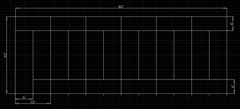
- Create a rectangle of 60' X 22' by the command "RECTANGLE", then put value (@60',20') and press enter.
- Then explode the rectangle by the command "EXPLODE"
- Divide 60' into 10' columns (five times) and again divide each 10' to 5' by using "offset" command. ( Command "Offset", select left side line and give offset distance as 10' first and for the second as 5'.
- Create row at 2' and 4' respectively by offset command. ( Command "OFFSET" - select the top line and give distance as 2' again command "OFFSET" - select bottom line and give offset distance as 4' ).
- Again offset 0'-8" from bottom line and right side line, then extend lines towards that created line and then erase those offseted lines.
- Trim off unnessary lines.
Entering Text:-
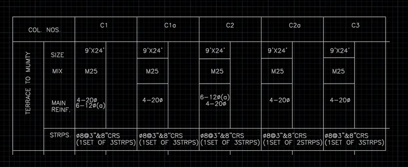
Enter the text in the table by using single line text from the drop down menu- Specify the point of text- specify the text height as 0'-8" and set text angle as zero degree, in case the text " TERRACE TO MUMTY" Give text angle 90 degree and type the text. After entering the text, right click and select properties- then list of properties will be displayed - ensure that the text height is 0'-8" and make justify: as left.
- To change the style of text command "ST", a dialogue box appears and select the font name as "romans.shx" .
- Then insert all the text or copy the text created and edit it to the required text in respective row and columns
- Give the heading as column schedule.
- Type a command "LINE" then draw it between text of 5th,7th,9th and 11th column according to given table.
- Type all texts as per given Table details and to get reinforcement dia symbol type (%%c).
Drawing the column section:-
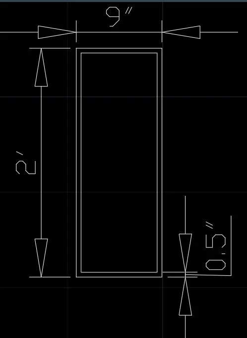
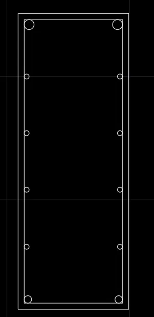
a. Drawing column section C1 - Column of size 9"X24" having 20mm dia reinforcement at 4 corners and 12mm dia 6 reinforcement bars in between connected by 8mm dia stirrup.
- Draw a rectangle of size 9"X24" ( by command "RECTANGLE" then specify a point - click on dimension in command box - then enter the first value as 9" and second dimenion as 24").
- Draw the column outline after a cover of 40mm i.e, 0.5" by offset command "OFFSET" - select the object - give offset distance as 0.5".
- Explode the inside rectangle so that the line can be selected seperately. ( Command "EXPLODE" - select the inner rectangle- press enter)
Drawing Reinforcement:-
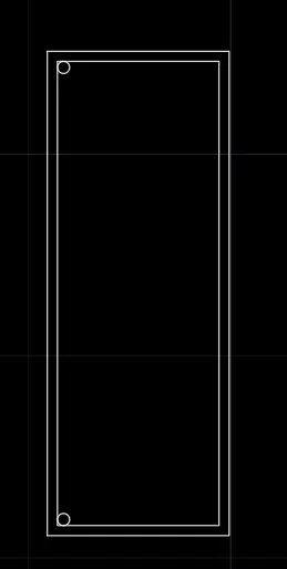
- By circle draw the reinforcement ( Type a command "circle" - select tan tan radius on the command box - select the left line as one of tangent - top line as another tangent - give radius as 10mm i.e., 0.4")
- Using mirror command create the reinforcement on the bottom of the left side column. ( Type a command "MIRROR" -select the object - give the mirror plane as the midpoint of the 2 line by object snap- midpoint on- select erase source object as "NO")
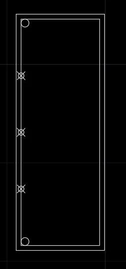
- Divide the line containing the reinforcement by command "DIV" - select the object(line) -number of segments to be divided is given as 4, the line will be divided.
- To make the point of division visible, type a command "DDPTYPE" in command box, a dialogue box will appear and select the suitable point type- apply.
- Draw circles using two-point circle option and select the first point as the center of those points and give the length of second as 0.4" then press enter (Keep the ortho mode on during the entire process).
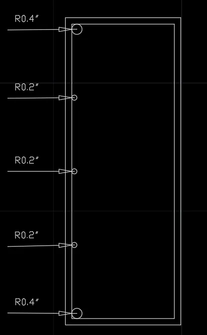
- Deelete the points
- Mirror the points to the right side by the command "MIRROR" - Select all the 6 circles , then draw the mirror plane as the midpoint of the 9" line and give erase as source object as "NO".
Drawing Stirrups:-
- Connect the reinforcement of radius 6mm, first row from the top, second row top and bottom, then third row from bottom.
- Connect the lines as top tangent of the two circles.
- Draw the rings by arc -3 point method, and mirroring it.
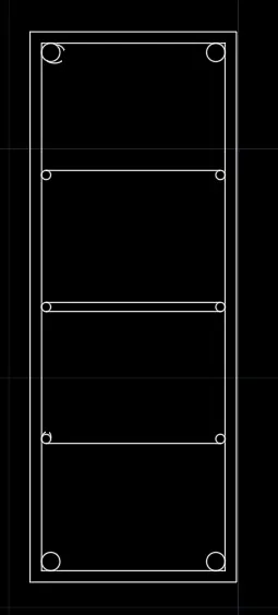
- Trim the corners of reinforcement intersecting with circle.
- Use "DONOUT" command to fill the circle, specify the inner diameter as zero and outer diameter as 0.8" for four corner reinforcement and for inside reinforcement specify the inner diameter as zero and outer diameter as 0.4" - specify center of donout, it gets filled. Mark "a" for in between reinforcement to indicate it as 12mm diameter.
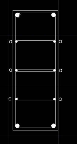
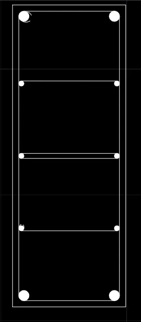
b. Drawing column section C1a - Column of size 9"X24" having 16mm dia reinforcement at 4 corners and 16mm dia 6 reinforcement bars in between connected by 8mm dia stirrup.
- Draw a rectangle of size 9"X24" ( by command "RECTANGLE" then specify a point - click on dimension in command box - then enter the first value as 9" and second dimenion as 24").
- Draw the column outline after a cover of 40mm i.e, 0.5" by offset command "OFFSET" - select the object - give offset distance as 0.5".
- Explode the inside rectangle so that the line can be selected seperately. Command "EXPLODE" - select the inner rectangle- press enter.
Drawing Reinforcement:-
- By circle draw the reinforcement ( Type a command "circle" - select tan tan radius on the command box - select the left line as one of tangent - top line as another tangent - give radius as 16mm i.e., 0.4")
- Using mirror command create the reinforcement on the bottom of the left side column. ( Type a command "MIRROR" -select the object - give the mirror plane as the midpoint of the 2 line by object snap- midpoint on- select erase source object as "NO"
- Divide the line containing the reinforcement by command "DIV" - select the object(line) -number of segments to be divided is given as 5, the line will be divided.
- To make the point of division visible, type a command "DDPTYPE" in command box, a dialogue box will appear and select the suitable point type- apply.
- Draw circles using two-point circle option and select the first point as the center of those points and give the length of second as 0.8" then press enter (Keep the ortho mode on during the entire process).
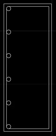
- Deelete the points
- Mirror the points to the right side by the command "MIRROR" - Select all the 6 circles , then draw the mirror plane as the midpoint of the 9" line and give erase as source object as "NO".
- Trim off the top and bottom corner reinforcements intersecting with circles.
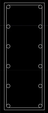
Drawing Stirrups:-
- With line command draw lines in top and bottom of reinforcements to show the stirrups same in the next set also.
- Draw the rings by arc -3 point method, and mirroring it, and trim of the unnecessary portion of arc.
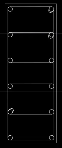
- Use "DONOUT" command to fill the circle, specify the inner diameter as zero and outer diameter as 0.8" for four corner reinforcement and for inside reinforcement specify the inner diameter as zero and outer diameter as 0.4" - specify center of donout, it gets filled. Mark "a" for in between reinforcement to indicate it as 12mm diameter.
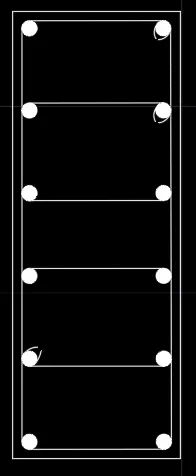
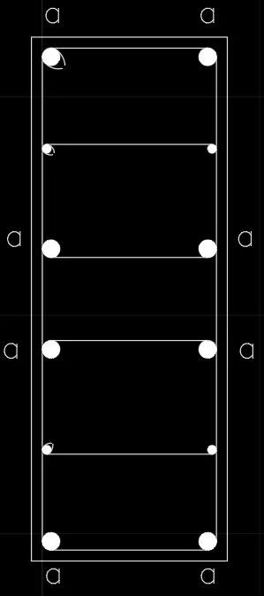
C. Drawing column section C2 - Column of size 9"X24" having 20mm dia 8 bars shown in figure as "a" and rest 12mm dia 4 bars with 8mm dia stirrups.
Drawing column-
- Draw a rectangle of size 9"X24" ( by command "RECTANGLE" then specify a point - click on dimension in command box - then enter the first value as 9" and second dimenion as 24").
- Draw the column outline after a cover of 40mm i.e, 0.5" by offset command "OFFSET" - select the object - give offset distance as 0.5".
- Explode the inside rectangle so that the line can be selected seperately. Command "EXPLODE" - select the inner rectangle- press enter.
Drawing Reinforcement:-
- By circle draw the reinforcement ( Type a command "circle" - select tan tan radius on the command box - select the left line as one of tangent - top line as another tangent - give radius as 20mm i.e., 0.4")
- Using mirror command create the reinforcement on the bottom of the left side column. ( Type a command "MIRROR" -select the object - give the mirror plane as the midpoint of the 2 line by object snap- midpoint on- select erase source object as "NO"
- Divide the line containing the reinforcement by command "DIV" - select the object(line) -number of segments to be divided is given as 5, the line will be divided.
- To make the point of division visible, type a command "DDPTYPE" in command box, a dialogue box will appear and select the suitable point type- apply.
- Draw circles for 1st and 4th point using two-point circle option and select the first point as the center of those points and give the length of second as 0.4" then press enter (Keep the ortho mode on during the entire process).
- Draw circles for 1st and 4th point using two-point circle option and select the first point as the center of those points and give the length of second as 0.8" then press enter (Keep the ortho mode on during the entire process).
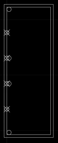
- Deelete the points
- Mirror the points to the right side by the command "MIRROR" - Select all the 6 circles , then draw the mirror plane as the midpoint of the 9" line and give erase as source object as "NO".
- Trim off the top and bottom corner reinforcements intersecting with circles.
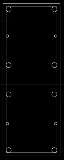
Drawing Stirrups:-
- With line command draw lines in top and bottom of reinforcements to show the stirrups same in the next set also.
- Draw the rings by arc -3 point method, and mirroring it, and trim of the unnecessary portion of arc.
- Trim off the top and bottom corner reinforcements intersecting with circles.
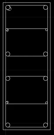
- Use "DONOUT" command to fill the circle, specify the inner diameter as zero and outer diameter as 0.8" for four corner and four middle reinforcement and for rest of the inside reinforcement specify the inner diameter as zero and outer diameter as 0.4" - specify center of donout, it gets filled. Mark "a" for in between reinforcement to indicate it as 12mm diameter.
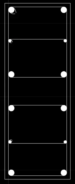
- Type a single line text "a" on side of 20mm dia reinforcement for identification.
D. Drawing column section C2a.
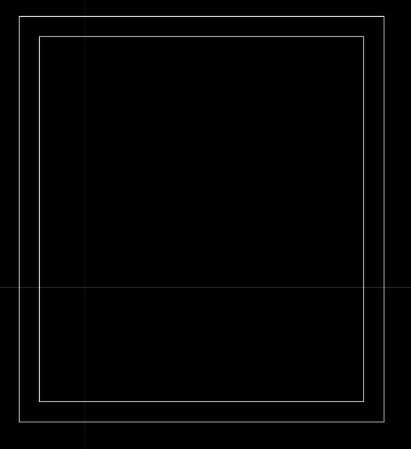
- Draw rectangle of 9" X 10" (@9",10") and give an offset of 0.5" and exploded the indide offseted rectangle.
Drawing Reinforcement-
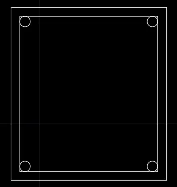
- With the "circle" command - select tan,tan, radius and select two corner lines and give radius as 0.3" (8 mm).
- Mirror this hole to the opposite side corners.
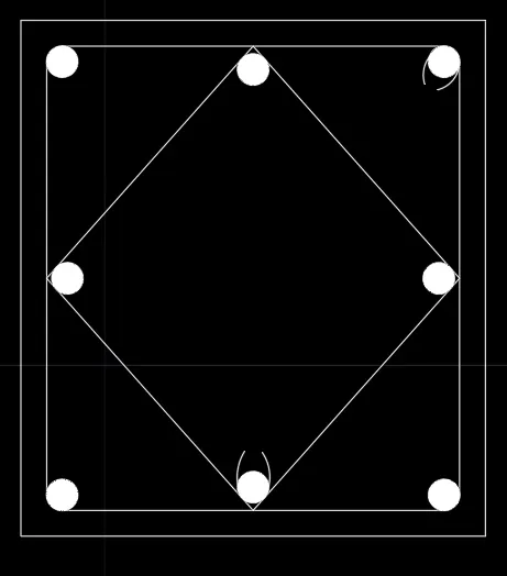
- Draw lines joining the midpoint of each side, then by command "CIRCLE" - tan tan radius - select the two sides as tangent and give radius as 0.3" as radius.
- Mirror the circles by opposite side by "MIRROR" command.
- Again draw the other side reinforcement as done above.
- Create rings by arc 3 point.
- Trim off the top and bottom side cornners intersecting with circles.
- Fill the reinforcement by command "DONUT" ( Give inner diameter as zero and outer diameter as 0.6" )
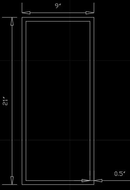
E. Drawing column section C3 - Column of size 9"X21" reinforcement of 16mm dia 12 numbers and stirrups of 8mm diameter.
Drawing Column-
- Drawing rectangle by "RECTANGLE" command and select a point, then give a dimension of 9" X 21" (@9",21")
- Offset the rectangle inside with a distance of 0.5" ( command "OFFSET" and set a distance of 0.5" )
- Explode the inner rectangle.
Drawing Reinforcement:-
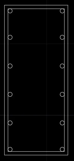
- By circle draw the reinforcement ( Type a command "circle" - select tan tan radius on the command box - select the left line as one of tangent - top line as another tangent - give radius as 16mm i.e., 0.3")
- Type a command "DIVIDE" then give 5 divisions for 4 points and type "DDPTYPE" and select point type.
- Draw circles for all middle points using two-point circle option and select the first point as the center of those points and give the length of second as 0.6" then press enter (Keep the ortho mode on during the entire process).
- Delete the points.
- Using mirror command create the reinforcement on the bottom of the left side column. ( Type a command "MIRROR" -select the object - give the mirror plane as the midpoint of the 2 line by object snap- midpoint on- select erase source object as "NO")
Drawing Stirrups:-
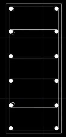
- With line command draw lines in top and bottom of reinforcements to show the stirrups same in the next set also.
- Draw the rings by arc -3 point method, and mirroring it, and trim of the unnecessary portion of arc.
- Creating rings with 3 points-arc
- Trim off the top and bottom corner reinforcements intersecting with circles.
- Fill the reinforcement by command "DONUT" ( Give inner diameter as zero and outer diameter as 0.6" )
RESULT:-
FINAL SKETCH OF COLUMN SCHEDULE TABLE.
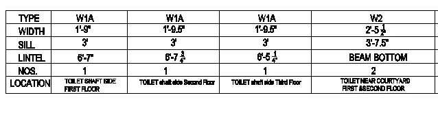
AIM:- To Create a window schedule as shown in the figure.
INTRODUCTION:-
To draw this window schedule, I have used several autocad commands like- line, trim, offset, text etc.,
PROCEDURE:-
Open Autocad and type a command "Unit" and press enter, then set unit as Engineering and set angle in degree- base angle is east -mark angle direction as anticlockwise. Type a command "DIMSTYLE" and press enter, then click to modify and go to primary unit tab and set it Engineering and set the precision to 0'-0" and cick ok.
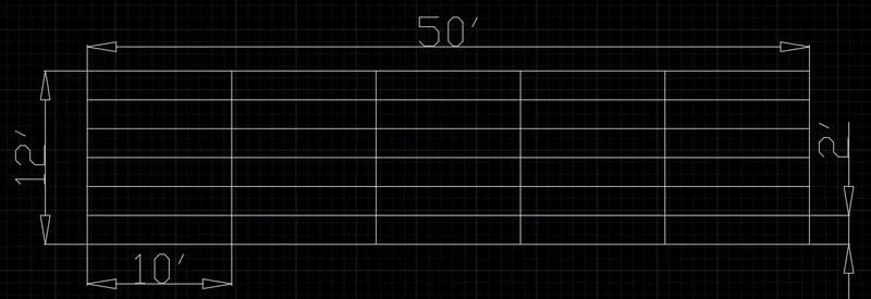
- Create a rectangle of 50' X 12' by the command "RECTANGLE", then put value (@50',12') and press enter.
- Then explode the rectangle by the command "EXPLODE"
- Divide 50' into 10' columns (five times) ( Command "Offset", select left side line and give offset distance as 10' )
- Create 6 number of rows of 2' distance by offset command. ( Command "OFFSET" - select the top line and give distance as 2' for six times).
Entering Text:-
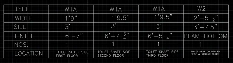
Enter the text in the table by using single line text from the drop down menu- Specify the point of text- specify the text height as 0'-11" and set text angle as zero degree. After entering the text, right click and select properties- then list of properties will be displayed.
- To change the style of text command "ST", a dialogue box appears and select the font name as "romans.shx" .
- Then insert all the text or copy the text created and edit it to the required text in respective row and columns and rows.
- For 2nd, 3rd, 4th column bottom rows, I used 0'-6" text height and for 5th column bottom row, I have used 0'-4" text height.
- For type the number (use multiline text) eg. 6'-7 3/4" then enter a space, the fraction will be stacked horizontally.
RESULT:-
FINAL SKETCH OF WINDOW SCHEDULE TABLE.
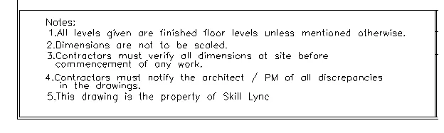
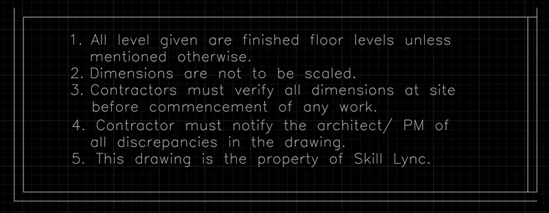
AIM:- To Create the drawing template as shown in the figure by Using the Notes as in the figure.

INTRODUCTION:-
To draw this drawing template, I have used several autocad commands like- rectangle,Line, text, offset,erase etc.,
PROCEDURE:-
For 1st Template-
- Create a rectangle of 46' X 16' by the command "RECTANGLE", then put value (@46',16') and press enter.
- Take an offset of 0'-0.8" outside of that rectangle and then explode both the rectangle.
- Erase the top line of outside rectangle, then extend inner side rectangle top and bottom line towards right side lines.
- Then trim off accordingly.
- To change the style of text command "ST", a dialogue box appears and select the font name as "romans.shx" .
- Select multiline text and set text height as 0'-11".
- Type your text as per given information.
RESULT:-
FINAL SKETCH OF DRAWING TEMPLATE.
For 2nd Template-
Create Table:-
- Create a rectangle of 120' X 15' by command "RECTANGLE" command give coordinate as @40',15'.
- Then explode that rectangle, and take an offset two times of 40' for left sided column of rectangle.
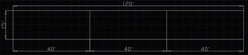
- Divide the second column of table into two rows from top ( Command "OFFSET", then set offset distance 3' and select the object select the rows from top of 2nd column)
- Also divide the third column into four each of 10' by command "OFFSET" and trim the unwanted lines.
- Again divide the third, fourth, fifth and sixth column into 5 more rows by command "OFFSET" and give a distance of 3'.
- Offset outside retangle lfet side and bottom side and 2nd and 3rd column into 0'-8" for aesthetic beauty of table.
- Draw a perpendicular line in 3rd column's fourth row.
- Table is created

Inserting Text-
- Select multi-line from drop down list of text - create the text box, then type the data given.
- Text height is given as 8"
RESULT:-
FINAL SKETCH OF DRAWING TEMPLATE.

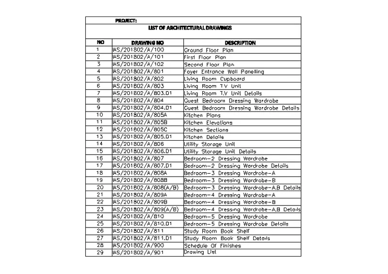
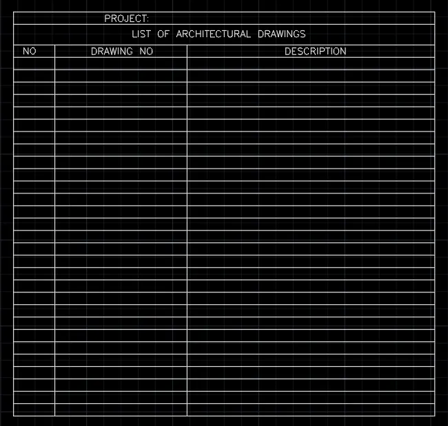
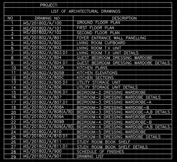
AIM:- To Create the list of drawing schedule as shown in the figure.
INTRODUCTION:-
To draw this drawing schedule, I have used several autocad commands like- rectangle, text, offset,erase etc.,
PROCEDURE:-
For 1st Template-
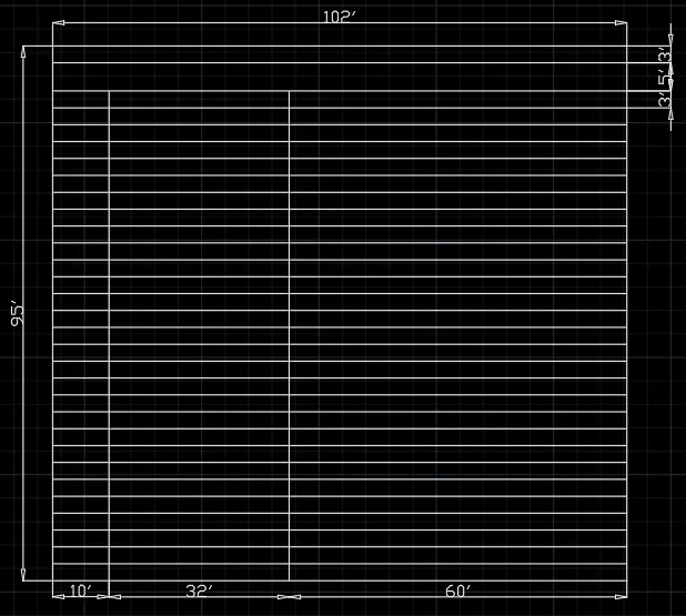
- Create a rectangle of 102' X 95' by the command "RECTANGLE", then put value (@102',95') and press enter.
- Explode the rectangle.
- Draw the columns by "OFFSET" command with a distance of 10',32' respectively from the left side.
- Create the rows by offseting distance of 3',5' and 3' from the top side of the headings.
- Trim off the unwanted lines.
- With "OFFSET" command give a distance of 3', then create such 29 number rows from 3rd row of previous table.
Inserting heading Texts:-
- With multiline option from the text drop down menu, create a text box in the 1st row and type "PROJECT:" with text height 1'-7" and style as romans.shx
- In the second row using multiline text type "LIST OF ARCHITECTURAL DRAWING" with text height of 1'-8".
- In third row type " NO:" , " DRAWING NO:", "DESCRIPTION" in respective columns with multiline text of height 1'-7" and same style.
Inserting Texts:-
- Select multiline option from the text drop down menu, then type text height 1'-7" and style as romans.shx
- Type texts accordingly.
RESULT:-
FINAL SKETCH OF DRAWING SCHEDULE.
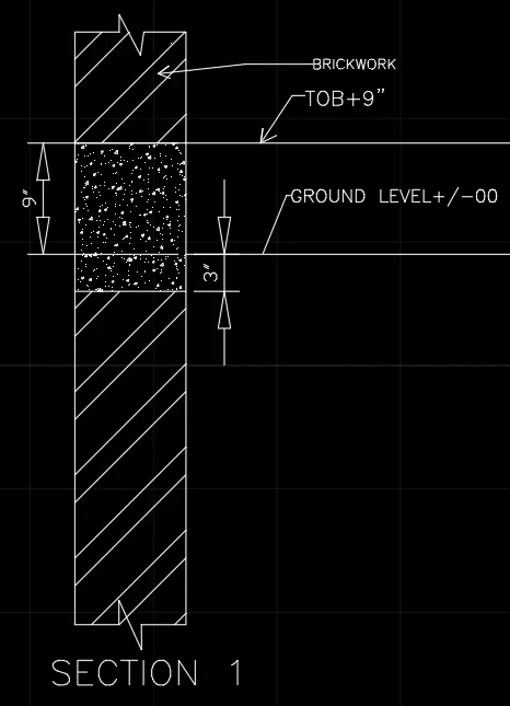
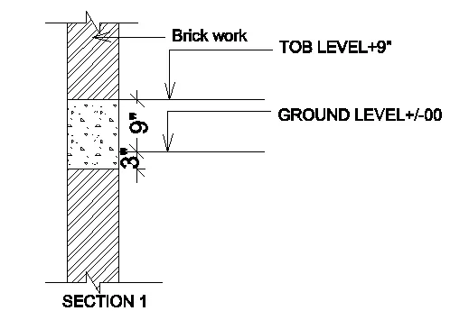
AIM:- To Create the Beam detail as shown in the figure and provide text wherever given.
INTRODUCTION:-
To draw this beam details, I have used several autocad commands like- Line,Hatch, text, offset,erase, dimension etc., and I set dimension (Engineering) in Autocad. Moreover, I set limits with command "Limits", specify the left corner points ans right corner points and then enter zoom all("z-a") in this drawing. Also, I used dimesion command for measuing the dimensions in Autocad along with text command to write drawing name.
PROCEDURE:-
Open Autocad and type a command "Unit" and press enter, then set unit as Engineering and set angle in degree- base angle is east -mark angle direction as anticlockwise. Type a command "DIMSTYLE" and press enter, then click to modify and go to primary unit tab and set it Engineering and set the precision to 0'-0" and cick ok.
- Draw cross section of beam with height 4' and thickness 9" (wall thickness)
- With command "LINE", draw a line of 4' in +Y direction and 9" in +X direction and 4' downwards and close.
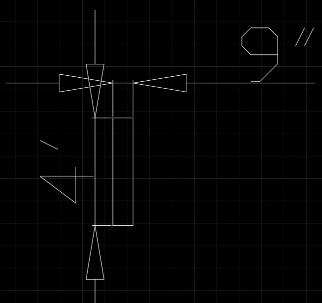
- From top give an offset of 9", which marks the ground level, command "OFFSET" - select the top portion - give the offset distance as 9" and extend the ground level line.
- Then give an offset of 3" from 9" line command "OFFSET" - select the 9" line - give offset distance as 3", which indicate the bottom level of concrete.
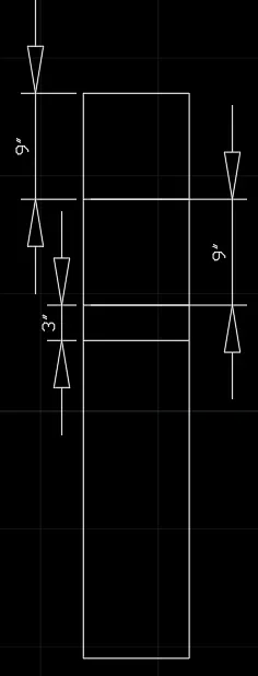
- Draw horizontal lines to show TOB level and Ground level, and using "LINE" command draw continue symbol.
- Erase unnessary lines.
- Hatch the portion of brick and concrete.
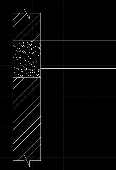
Inserting Texts:-
- Use "LEADER" command and edit texts accordingly.
- Use text accordingly.
RESULT:-
FINAL SKETCH OF BEAM DETAILS.