Creation of Column Schedule and Drawing Template using AutoCad
1.
AIM : create column schedule with the help of lines. also, insert test with the help of dtext command or single line text.
INTRODUCTION :
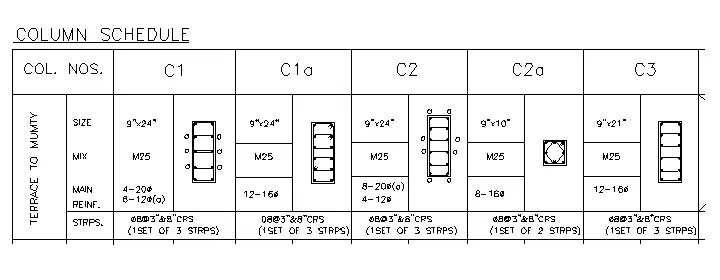
column schedule is a schedule in which the details of the column collected in the construction of design purpose. in this drawing we are creating schedule of column in autocad. we will used the line command for test we will use Dtext command, roman.shx type as font name with 8" text height and jusitfy text from left side. the procedure of drawing explain in detail.
PROCEDURE :
step-1:
- type UN command to setup drawing units to engineering.
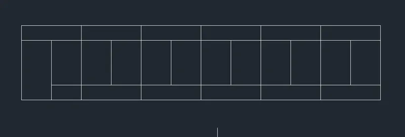
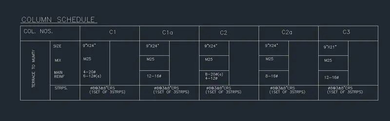
- first we need to make tables by using lines, offset, trim command as show below.
step-2 :
- go to text style set function as given
- set font name to romans.shx
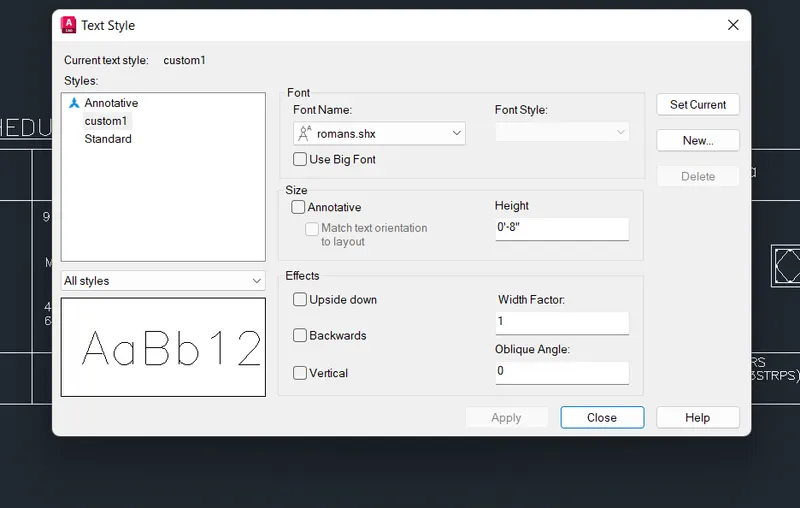
- height to 8"
- type Dtext command press enter
- justfy to left
- select start point and select rotation angle 0 degree. press enter.
- for ' terrace to mumity' text specify rotation angle 90 degree.
- type text as given.
step-3 :
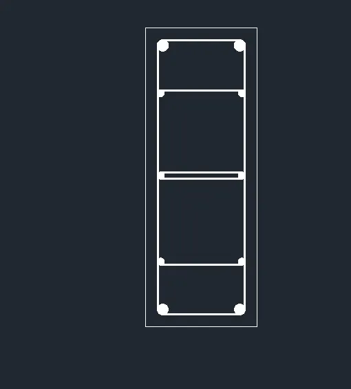
- type rec for rectangle
- specify first corner point
- select dimension
- specify length of rectangle : 9"
- specify width of rectangle : 24"
- select lineweight to 20mm
- take offset command make offset 1.5".
- for column cover we provide 40mm cover as 1.5".
- use offset make horizontal lines
- type circle, select tan tan radius make circle of different sizes and it will create circle i which edges of the circle will touch to corners.
- four corner circle have 20mm dia.
- and other have 12mm dia.
- convert this mm to dia and specify radius.
- use hatch command select solid and hatch the circles.
- trim the corner properly so that the corner should not be pointed.
- make other object using above process
step-6 :
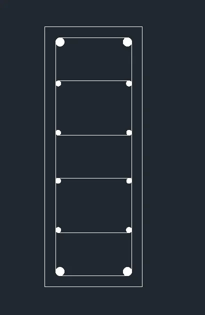
- make rectangle of length 9" and width of 10"
- take offset of 1.5"
- take line command and join the mid point of lines so that rect will create inside the rec
- use circle command select tan-tan radius and make corner circle of having 0.23" radius
-
step-7
- finally keep ortho mode off
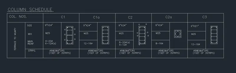
- move all this object in table
- paste it as shown in figure.
RESULT :
thus, we created column schedule using dtext command.
2.
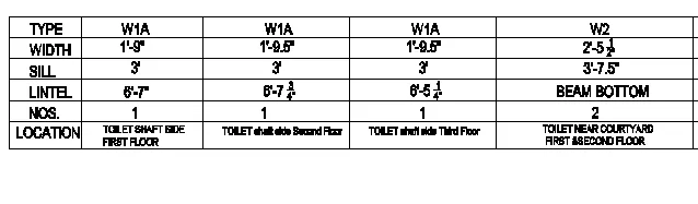
AIM : create window schedule
INTRODUCTION :
in this window schedule we are going to show detailing of windows such as type, width, sill height, lintel height, etc. we will used table and text command to draw it.
PROCEDURE :
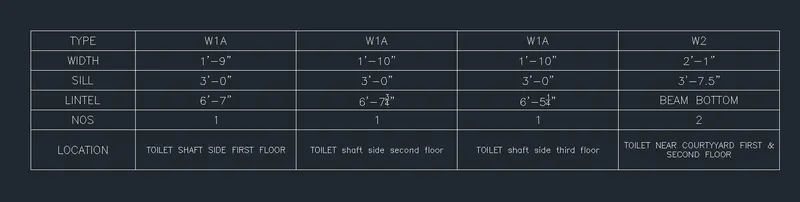
- type tab for table, set row-6 and column-5 set and cell style to data in all box.
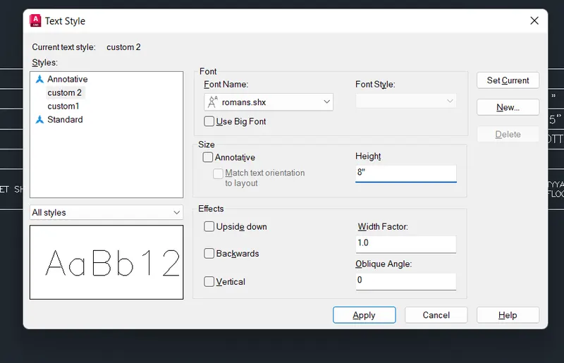
- type ST for text style
- font name select romans shx, height 8", press ok
-type everything as given in table with the justification middle mc.
RESULT :
thus, we created window schedule
3.
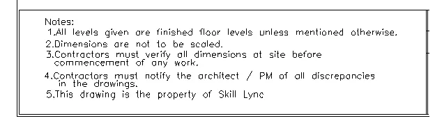
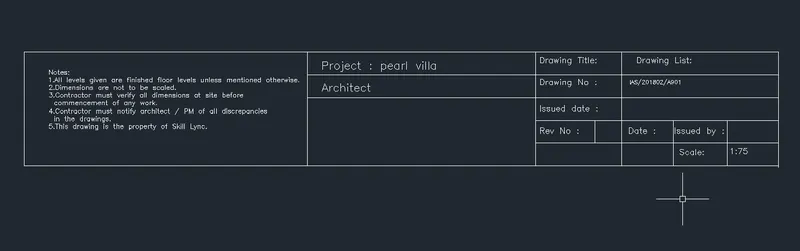
AIM : Create the drawing template as shown in the figure:< Use the Notes as in the figure>

INTRODUCTION :
notes concern the overall work information of the drawings. it render supplemental data. notes make sure no discrepancies arise between the architect and contractor engaged in the project. this table contains project name, architect name, drawing no., issued date etc.
PROCEDURE :
- Type L for line and make table as shown
- use offset and trim tools.
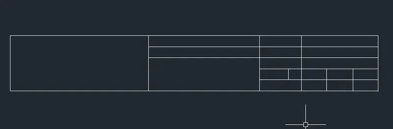
- type ST for text style
- use romans. shx as font name and set text height
- type Mtext for multiline text
- type data as given in the table.
RESULT :
hence, we created drawing template as given.
4.
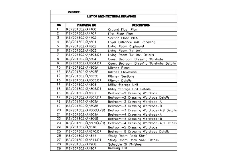
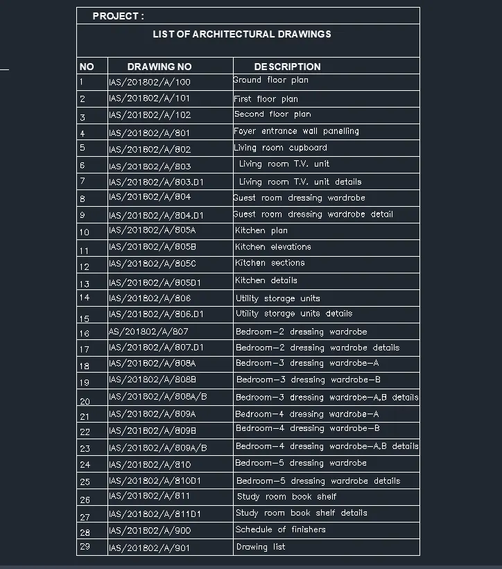
AIM: Create the list of drawing schedule as shown in the figure
INTRODUCTION:
schedule drawing is itemised list of drawings required for building projects. schedule of drawings may include all the drawings required for project . it may be specifically prepared for certain discipline or for particular aspect of the work.
PROCEDURE :
- first make table
- type tab for table format
- select no of column required 3
- select no of rows required 32
- select header data and title for it.
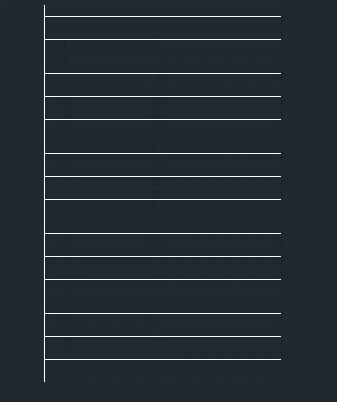
- use mtext for multiline text and type data as given.
RESULT :
Thus we Create the list of drawing schedule as shown in the figure
5.
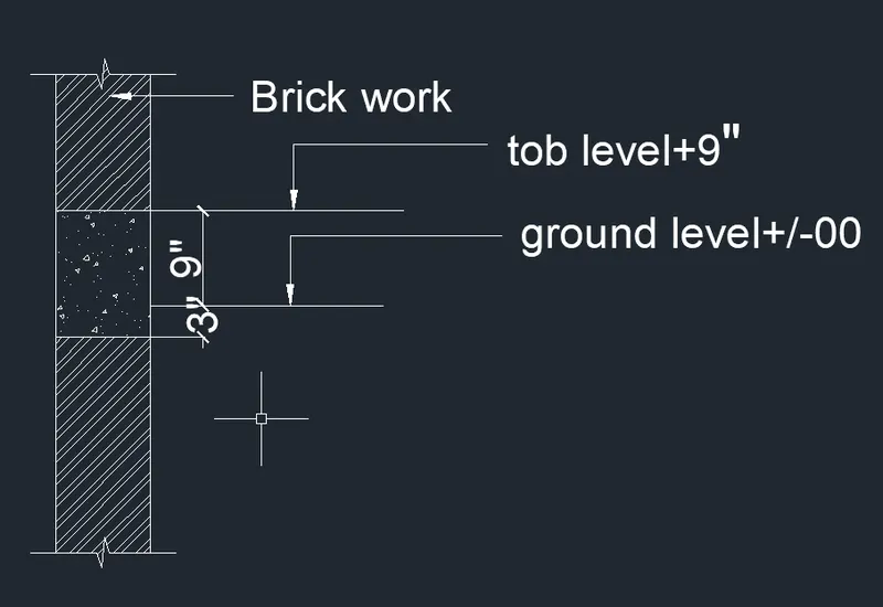
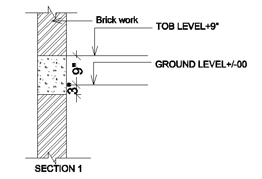
AIM : Create the Beam detail as shown in the figure and provide text wherever given.
PROCEDURE :
- type line command make a vertical line
- make offset of 9"
- type breakline make two breakline
- make offset of bottom line 2' offset
- then 1' offset
- then 1' offset
- we will get 3 sections
- hatch this sections using hatch tools
- scale it by hatch edit option
- use Mleader with two point to write ' brickwork'
- use Mleader with three point to write other data.
- using DImlin give the dimensions
RESULT :
thus, we create beam detail as shown in figure.