Creation of Column Schedule and Drawing Template using AutoCad
INTRODUCTION- This challenge (5) is based on the creation of window schedule,column schedule,hatching the drawings.
AIM-To design window schedule,column schedule, and drawing templates in AutoCAD 2019 version.
COMMANDS USED-Offset,rectangle,line,erase,trim,dimension,DIMS,units,limits.
-:STEPS FOR Ist diagram:-
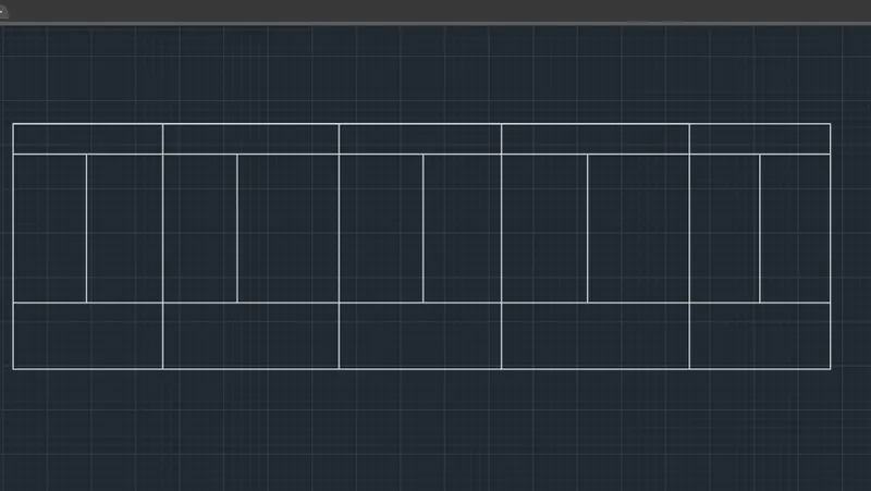
- Create a rectangle of (50'*20') and provide 5 columns in this rectangle of length 20' and width of 10' and now from upper left corner of this rectangle drop 2' line in -ve y-axis let it pass another line at the point created similarlyfrom 4' draw another line to intersect the rectangle and draw line in each rectangle to create sub -columns.
- Create rectangles of 9"824",9"*25" and 9"10" and create another rectangles inside of each rectangles by using offset tool for C1,provide 3 lines in sub rectangles draw mini circles in each corner points created.
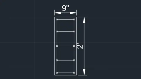
- Provide 4 lines at equal gaps in sub rectangles of 9"*24".
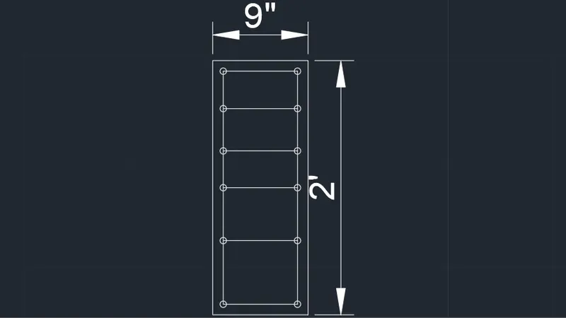
- For C2-same like C1.
- For C2a-Create mid-points of sub-rectangles and join lines to each connecting points draw mini circles to all points of the sub-rectangle.

- FOR C3-here,we will draw same rectangle in same manner like C1 just put length of 25' in place of 24".

- (II)
- Type M25 as strength for each ,provide main reinforcement as 4-20diaand 6-12 dia for C1,12-16dia for C1a,for C2 provide 9-20dia,4-12dia,for C2a provide 8-16dia and for C3 provide 12-16 dia dia reinforcement provide 1 set of strips of dia 8@3" and of CSR 8".
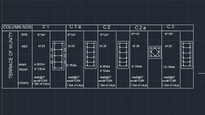
STEPS FOR (IInd diagram)
- Create (50'*20') rectangle and create sub columns at 10' gap horizontally,create vertical rows at 1.5' gap vetically.
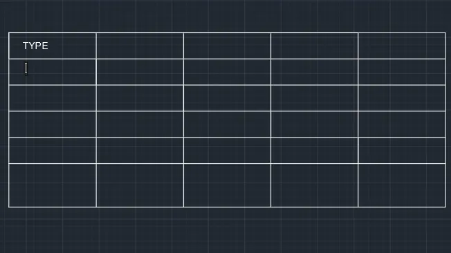
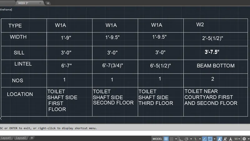
- Type sill,width,location,lintel,numbers in left-most column and fill 1st row -W1A,W1A,W1A AND W2,fill in width in second row as-1'-9",1'-9.5",1'-9.5" and 2'-5.5",
- Fill SILL as -3'0',3'0",3'0" and3'0.75",fill lintel as-6'7",6'-7(3/4)",6'-5.5",beam bottom, numbers as-1,1,1,2 ,fill location as toilet shaft side first
STEPS FOR (IIIrd diagram)
- Create (110'*20') rectangle and divide this rectangle into 4 columns at 15',15',15' ,65' spacings and creating 2 rows in 2nd column,5 rows in 3rd column and 4th column.
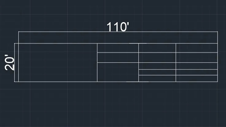
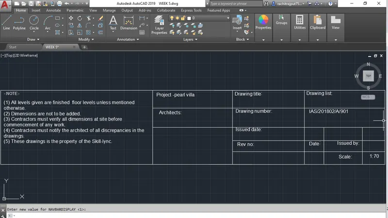
- Fill all the details as per the question in 1st column,2nd column,3rd column and 4th columngiven as per the question to get the desired final result.
STEPS FOR 4TH DIAGRAM
- Draw rectangle and provide length of 28' here we will provide 3 columns,one mini column for writing serial numbers,one for designation and 3rd column for writing all floor plans,house plan details.
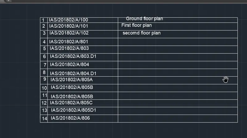
- Finally, we will fill all the details in 28 serial numbers as per the question such as IAS/201802/A/100......IAS/20/802/A/900 and in 3rd column fill all the housing details to get the desired result.
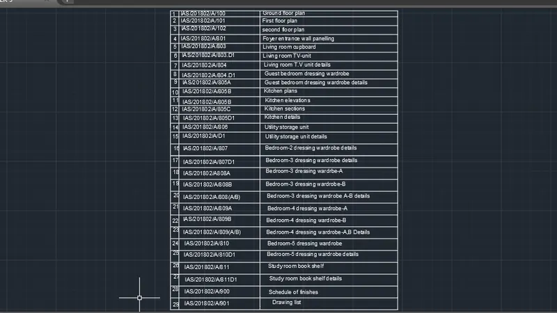
STEPS FOR 5TH DIAGRAM
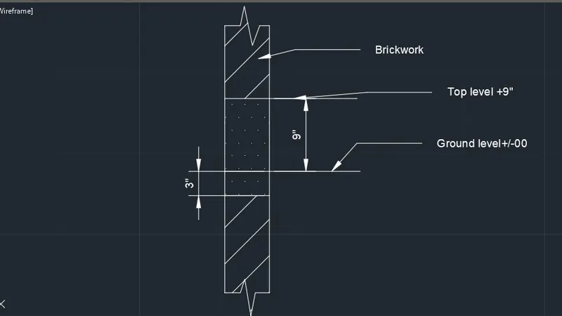
- Draw rectangle of 32"*3" and in between the rectangle provide9" length in between top level and ground level,below G.L ,give 3" line length and above top level provide brick work,create zig-zag pattern in top and bottom lengths and finally provide hatching to the 3 components of the rectangle by using hatching tool.
-:RESULT:-
- We have drawn column schedule,window schedule and drawing templates sucessfullyin AutoCAD 2019 version.
-