Creating a Floor plan, Footing detail and Isometric view using AutoCad
INTRODUCTION-TO DRAW THE FLOOR PLAN,FOOTINGS AND ISOMETRIC DETAILS IN AutoCAD 2019.
AIM-TO DRAW THE C1,C2,C3,C4,C5,C6 GEOMETRIES IN AUTOCAD USING LINE ,RECTANGLE PROPERTIES.
COMMANDS-LINE,RECTANGLE,TRIM,ERASE,LIMITS,GRID,UNITS,ISOMETRIC COMMANDS.
COMMON STEPS
- Specify units,sets limits,specify grid.
STEPS FOR C1
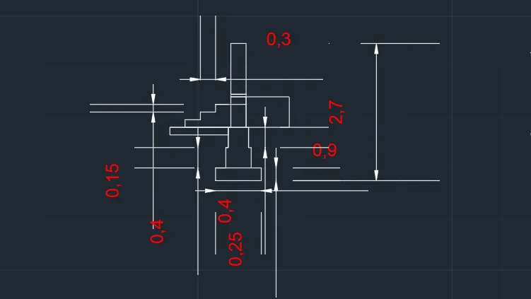
- Specify first point as (1,1) and draw a rectangle of 0.9*0.25,similarly drawing rectangles from top length of each rectangles i.e from 0.9*0.25 and at 0.2 distance from left point of top length draw rectangles of 0.5 and 0.4 and similarly drawing (0.4 * 0.4),(0.3*0.6),(1.05*0.3) to complete the half the drawing.
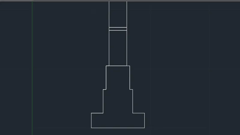
- At rectangle (0.3*0.6) ,from right side of rectangle draw another rectangle of length 0.6 and from (0.3*0.4) rectangle at bottom point towards left side give line command of 1.2m and by adopting coordinate system method complete the styairs of (0.3 and 0.15) lengths.
STEPS FOR C2
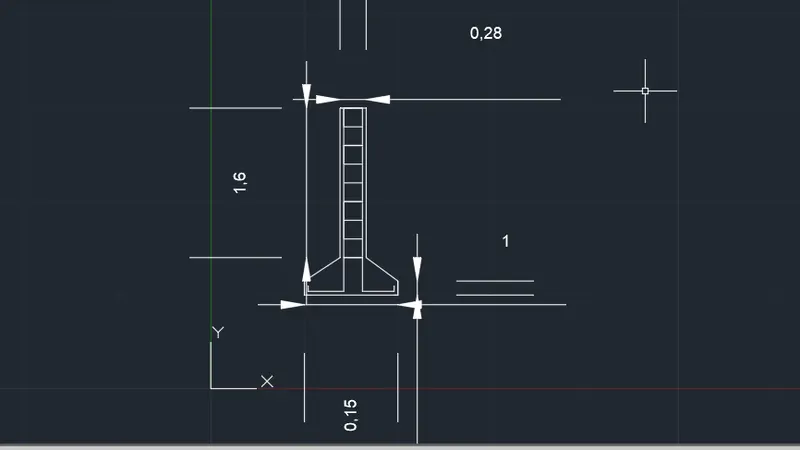
- Specify first point as (1,1),thenk draw a rectangle of (1*0.4),using coordinate system at 0.38 draw vertical rectangle at middle of top length i.e. of (1.6*0.24),again use C/S method at 0.04 of top length of 12st rectangle draw another rectangle of (1.6*0.16).
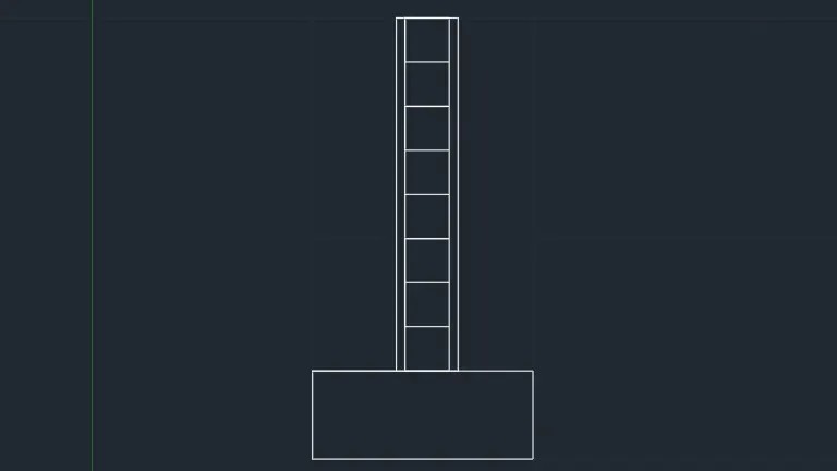
- Using trim command and C/S method we will shape the diagram,at lowestr point at distnce of 0.04 join the length to comp,ete the isolated footing.
STEPS FOR C3
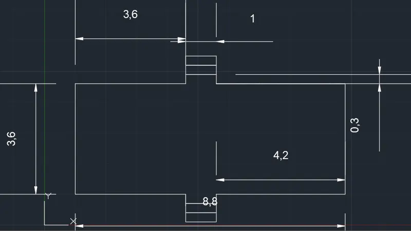
- Specify first point as (1,1),then draw a rectangle of (8.8*3.6),at 4.2 distance from ryight top corner at length of 8.8 draw another rectangle of (0.3*1) and same at lower left corner at 3.6 distance draw rectangle of (0.3*1).
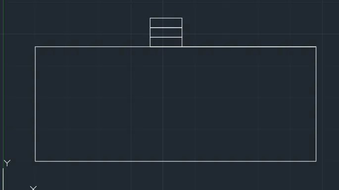
- Using copy selection command proceed the diagram and trim the lines of rectangles to complete the figure.
STEPS FOR C4
- Specify first point as (1,1) then draw rectangle of (0.9*0.45) then at 0.15 from top left corner of rectangle specify another point and draw rectangle of (0.6*0.4) similarly at 0.05 from topmost left corner draw rectangles.
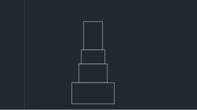
- Finally after drawing specify dimensions.
STEPS FOR C5
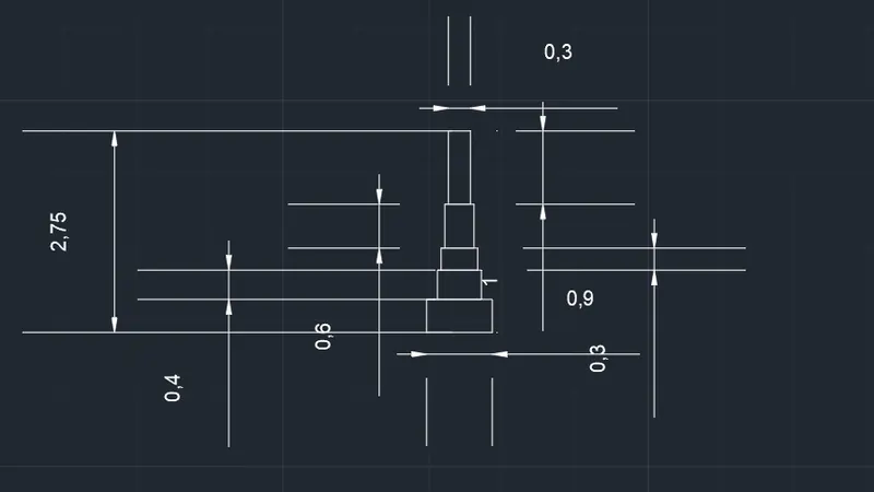
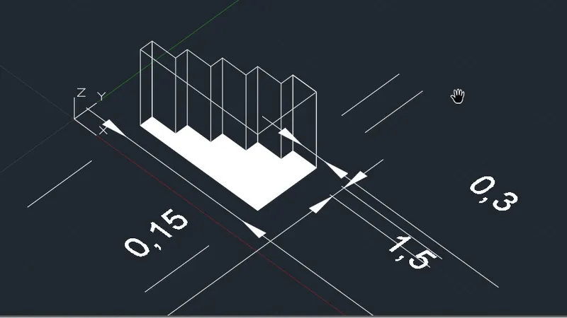
- Draw rectangle of (0.75 and 0.15) specify thickness of 1 dist,now form bottom right point towards (-ve x-axis) ,draw rectangles of thickness 1 disti.e. of (0.3*0.45),(0.3*0.3),and(0.3*0.15).
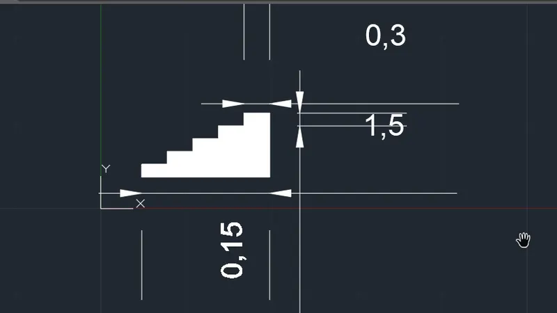
- Now,view the diagram in isometric manner ,trim the sides and specify the dimensions also provide hatching in top view.
STEPS FOR C6
- Draw rectangle of (3*3) and of thickness 0.3 a,again at 1 dist from bottom left point of rectangle draw rectangle of (2.42*1) having same thickness.
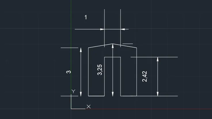
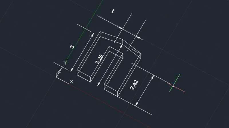
- View this diagram in isometric we get 3-d diagram pu8tr rectangle thickness zero and at 1.5 from top left of 3-d rectangle,dtraw lines of 0.25 from both sides of rectangle from top most points join lines to enclose the diagram.
- Note
- We have done 2nd step in 3-d view manner and created lines lines and distances as p5ervthe diagram.
RESULTS
- We have drawn floor plans,footings and isometric drawings in AutoCAD 2019 sucessfully