Creation of Column Schedule and Drawing Template using AutoCad
1. Aim: To create the column schedule of the building the Auto cad using engineering system.
- In a particular building various number of coumns and beams are provided with various sizes and shapes. In the design we need to specify the deatails like size and reinforcement details. so we need to prepare a schedule for the columns and beams separately.
- By using this schedule we can get know the details of the reinforcement details each.
Procedure :
- Click on new File and create the new template for potting the drawing.
- Now enter units (un) command and select the engineering system in the units and also set the precision of the units and insertion scale to inches and click on ok.
- Firstly we need to plot the plan or elevation of the building and locate the positions of the columns at the specified points.
- The column schedule can be prepared by the using the table,text and block command.
- The table can be crated from the annotation in the ribbon bar the table can be created by clicking the new option and the properties of the table can be modified as we required according to the schedule.
- The table mainly consists of Title,header and data.The table consists of the size of column and size of the row, text of the data. The boundaries of the table can be modified as we required and we need to mention the required column and rows and we can get the table in the model space.
- The title cell is used to mention the title of the schedule like schedule of columns or beams or doors etc.
- The addition of rows and columns can be modified according to the situtaion in the model space.
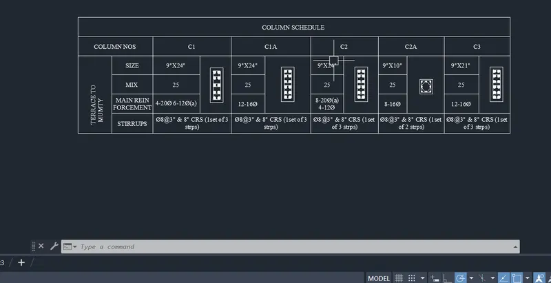
- Now using the Mtext or by clicking in the required cell we can mention the title,Size and mix proportion of the concrete.
- The schedule also gives the details of the main rein forcement, stirrups or hellical reinforcement along with the sizes.
- The model type of column or beam can be mentioned using the Block command.
- Now using the layers command assign layers to the table as we required.
- The final result of the schedule of columns is obtained as shown inthe below.
2. Aim: To create the window schedule of the building in the Auto cad using engineering system.
- In a particular building various number of doors and windows are provided with various sizes and shapes. In the design we need to specify the deatails like size and level . so we need to prepare a schedule for the doors and windows separately.
- By using this schedule we can get know the details of the doors or windows.
Procedure :
- Click on new File and create the new template for potting the drawing.
- Now enter units (un) command and select the engineering system in the units and also set the precision of the units and insertion scale to inches and click on ok.
- Firstly we need to plot the plan or elevation of the building and locate the positions of the doors and windows at the specified points.
- The window schedule can be prepared by the using the table,text and block command.
- The table can be crated from the annotation in the ribbon bar the table can be created by clicking the new option and the properties of the table can be modified as we required according to the schedule.
- The table mainly consists of Title,header and data.The table consists of the size of column and size of the row, text of the data. The boundaries of the table can be modified as we required and we need to mention the required column and rows and we can get the table in the model space.
- The title cell is used to mention the title of the schedule like schedule of doors or windows etc.
- The addition of rows and columns can be modified according to the situtaion in the model space.
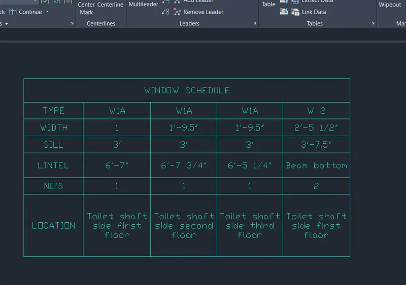
- Now using the Mtext or by clicking in the required cell we can mention the title,Size material, make and sill level of the window.
- The model type of door or window can mentioned using the Block command.
- Now using the layers command assign layers to the table as we required.
- The final result of the schedule of columns is obtained as shown inthe below.
3. Aim: To create the template and title block of the plan of the building the Auto cad using engineering system.
- For everey project or plan of the building we need to create the title block which consists of the name of organisation,architect scale of the drawing and other details of the building.
- The title block also mention about the revision of the drawing.
Procedure :
- Click on new File and create the new template for potting the drawing.
- Now enter units (un) command and select the engineering system in the units and also set the precision of the units and insertion scale to inches and click on ok.
- Firstly we need to plot the plan or elevation of the building and locate the positions of the columns at the specified points.
- The title block and template is prepared by the using the table command in th model space or by default we can create the template using the layout option and we need to edit the title block as we required.
- The template is prepared using the table command and using the merge option we can merge the cells and the details are emcomprised in the table.
- After creation of the template in the modelspace it is created with a view port and it is inserted in the layout option and it will be ready to plot.
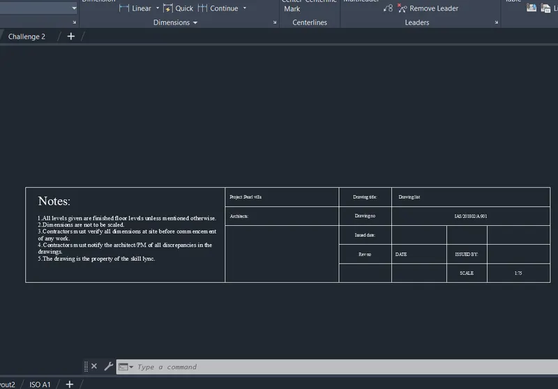
- The title template is very much useful and mandatory to get to know about the title of the project,scale, revisionnumber, name of the architect etc.
- The title template also contains the special notes which are not mentioned inthe plan or section or elevation etc.
- The final result of the template obtained is shown inthe below.
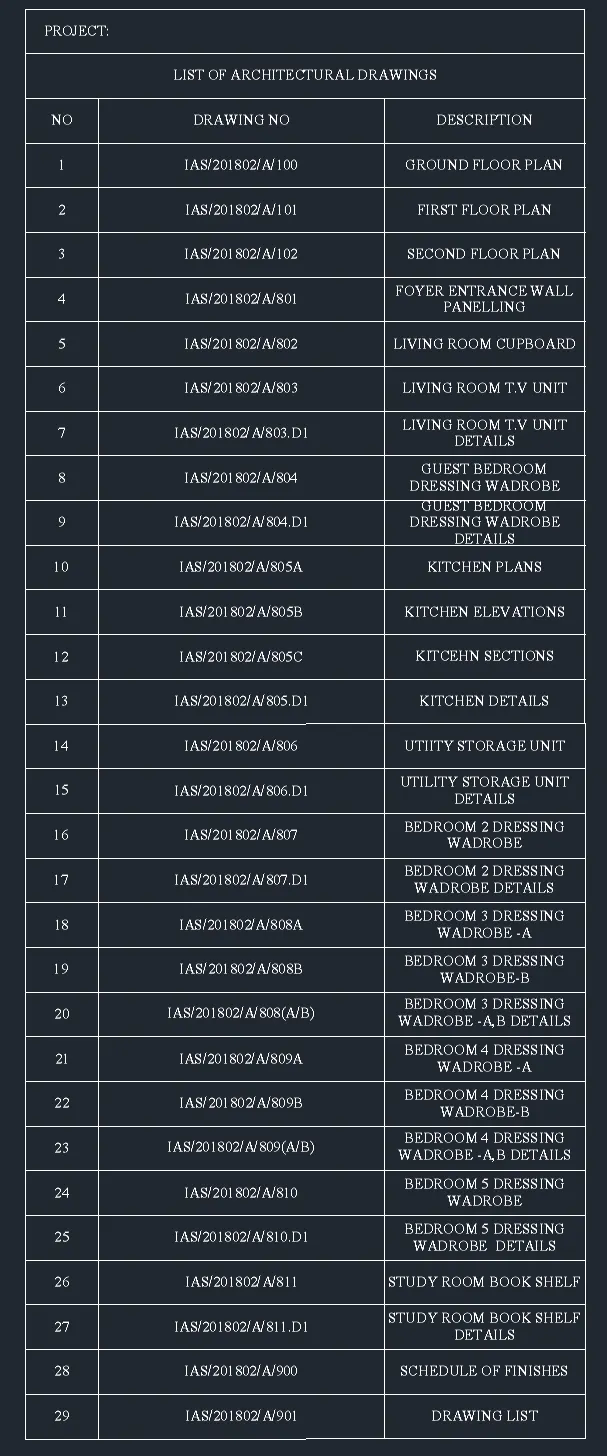
4. Aim: To create the schedule of the drawings of the building in the the Auto cad using engineering system.
- In a particular building various number of drawings are plotted for specifying the different details of the building.
- It may contain foundation drawing ,plinth beam drawing,electrical layout,plumbing layout ,furniture drawingetc. All these drawings are created to avoid the disturbance of the construction.
- By using this schedule we can get know the details of the foundation,plinth beam,plumbing,electrical,furniyure and other layout of the building.
Procedure :
- Click on new File and create the new template for potting the drawing.
- Now enter units (un) command and select the engineering system in the units and also set the precision of the units and insertion scale to inches and click on ok.
- Firstly we need to plot the plan,elevation of the building, the plan may contain plumbing,foundation,electrical,furniture roof beam plan,slab plan etc.
- A schedule is prepared for all the above drawings which gives the reference number and unique identity which can be easily identified for the checking and as well as execution.
- The drawing schedule can be prepared by the using the table,text and block command.
- The table can be crated from the annotation in the ribbon bar the table can be created by clicking the new option and the properties of the table can be modified as we required according to the schedule.
- The table mainly consists of Title,header and data.The table consists of the size of column and size of the row, text of the data. The boundaries of the table can be modified as we required and we need to mention the required column and rows and we can get the table in the model space.
- The title cell is used to mention the title of the schedule like schedule of drawings etc.
- The addition of rows and columns can be modified according to the situtaion in the model space.
- Now using the Mtext or by clicking in the required cell we can mention the title,name of the respective drawing,reference number for the drawing.
- Now using the layers command assign layers to the table as we required.
- The final result of the schedule of drawing is obtained as shown inthe below.
5. Aim: To create the beam in detail in the Auto cad using engineering system.
- In a particular building various number of columns and beams windows are provided with various sizes and shapes. In the design we need to specify the deatails like size and level and rein forcementg details.so we can get to know the details and internal strata of the any unit by plotting the sectional view of the unit.
- By using the sectional view we can get know the internal strata of the beam,column,door and window.
Procedure :
- Click on new File and create the new template for potting the drawing.
- Now enter units (un) command and select the engineering system in the units and also set the precision of the units and insertion scale to inches and click on ok.
- Firstly we need to plot the plan or elevation of the building the sectinal view can be plotted by cutting the plan or elevation either x or y axis of the columns and beams.
- The sectional beam can be plotted by cuuting in the y axis of the wall.
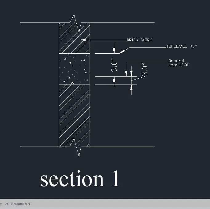
- Enter line or poly lline command plot the wall witht he thickness and height of the wall now using the off set commnad we can plot the beam by entering the bottom level and top level of the beam as offset distances.
- Now the internal strata can be mentioned by using the hatching command and we can canget know the strat according to the hatching done to the respective unit.
- Enter hatching in the command bar and select the hatch pattern which we required for a unit and it displays to pick the point and as we click on the area we can get the hactch pattern on the unit.
- Hatching can be done only to the close boundary of the unit .
- The hatching can be scaled according to the visibility and transparency of the hatch pattern we required, by using the hatch edit command.
- By using the dimlinear command we can measure the dimension of the wall.
- Uing the quick leader command we can mention the top and bottom level of the beam.
- The final result of the sectional view of the beam is obtained as shown inthe below.