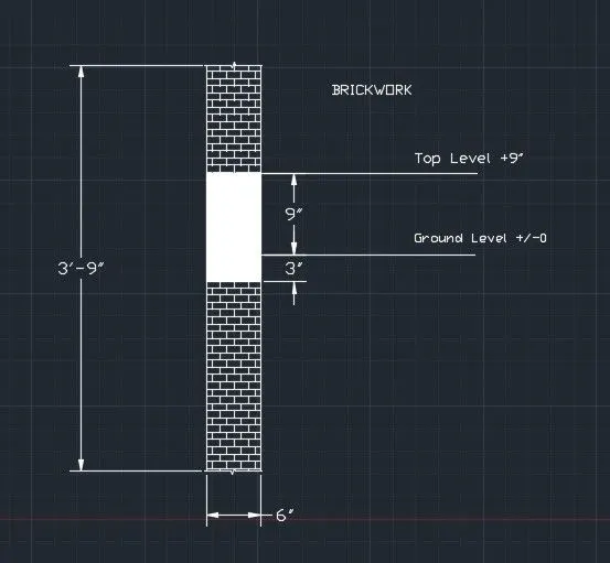
Creation of Column Schedule and Drawing Template using AutoCad
1.
Aim :-
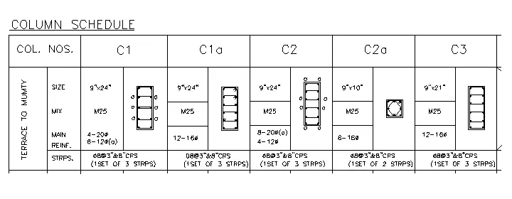
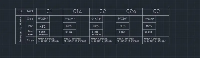
Creating a column schedule as shown in the figure.
Introduction :-
- There are 5 column schedules are diven in the table.
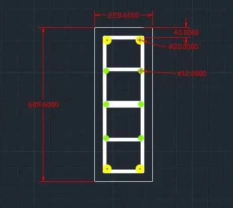
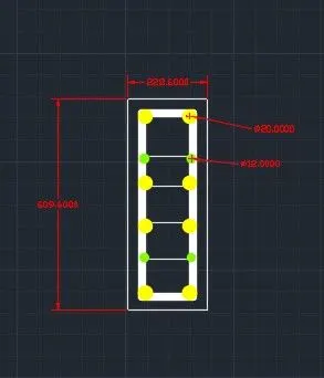
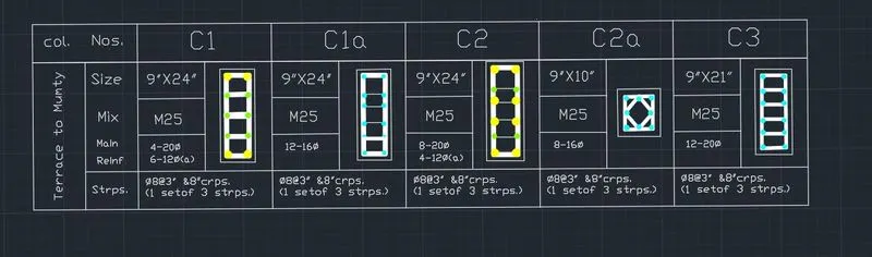
- Column C1 has size 9"X24", 4 nos. of 20 mm dia. and 6 no. of 12 mm dia. and 12 mm dia. bars are denoted as 'a'.
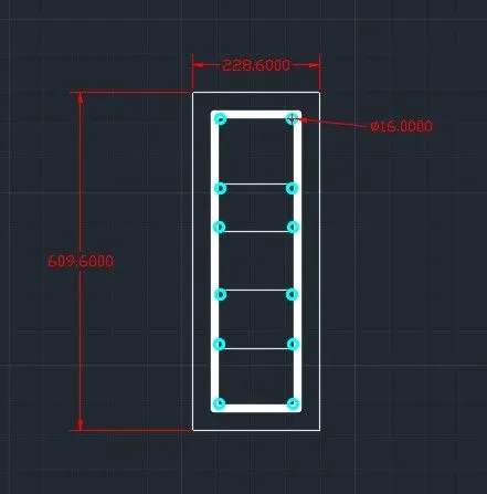
- Column C1a has size 9"X24", 12 nos. of 16 mm dia.
- Column C2 has size 9"X24", 8 nos. of 20 mm dia. and 4 no. of 12 mm dia. and 4 mm dia. bars are denoted as 'a'.
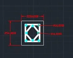
- Column C2a has size 9"X10", 8 nos. of 16 mm dia.
- Column C3 has size 9"X21", 12 nos. of 16 mm dia.
- All columns are provided with 8 mm dia. stirupps and 3" cc spacing near the ends and 8" in the middle.
- Approx 40 mm cover is to be assumed.
Procedure :-
- Convert every units in mm and draw the drawing as take unit of mm.
Values in Inches Values in mm
9 228.6
24 609.6
21 533.4
10 254
Drawing C1 :-
Drawing C1a :-
Drawing C2 :-
Drawing C2a :-
Drawing C3 :-
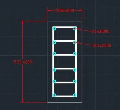
Table :-
- Using line command make a table as per drawing.
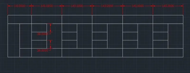
- Input the text as per the drawing.
- Input the Drawings as per drawing.
2.
Aim :-
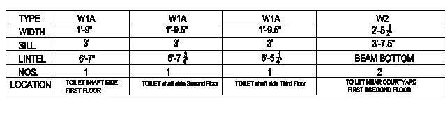
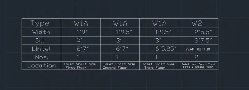
- Creating a window schedule as shown in the figures.
Result :-
- Using Line command make table and add text in the table.
3.
Aim :-
- Creating the drawing template as shown in the figure.
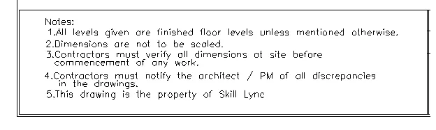

Result :-
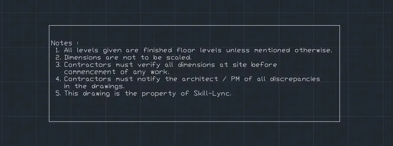
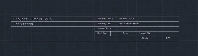
4.
Aim :-
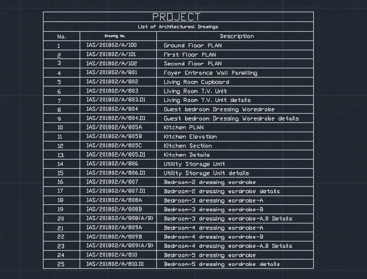
- Creating the list of drawing schedule as shown in the figure:
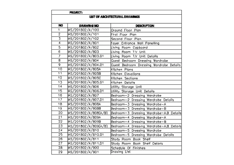
Result :-
- Open the table Command.
- Create a table style as per the drawing requirement.
- Enter the No. of rows and columns.
- Plot the Table.
- Add the text as the in the drawing.
5.
Aim :-
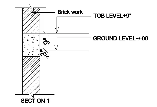
- Creating the Beam detail as shown in the figure and provided text wherever given.
Result :-
- MAke two lines parallel to 45" at a distane of 6".
- Use breakline command at both ends.
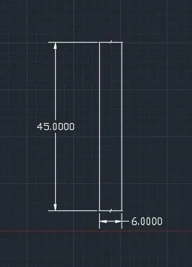
- Give required labelling using dimension.
- Give the hatching of brickwork and concrete.