Creation of Column Schedule and Drawing Template using AutoCad
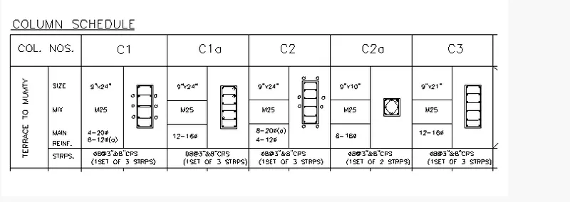
Aim - To create the Column Schedule as shown in figure .
Introduction -
i) The details of Column Schedule drawing is helpful for contractor as well as structural engineer to
understand details about size of column , reinforcement etc
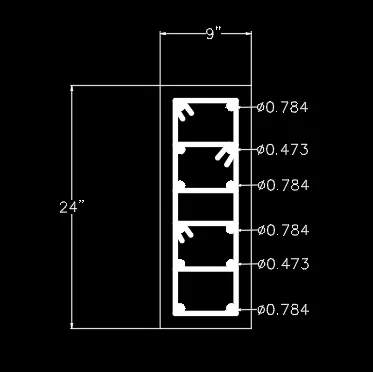
ii) In given fig Column C1 is provided with 4 bars of 12mm dia . and 6 bars of 20mm dia . Size of column is
9" x 24" .
iii) In given fig Column C1a and C3 is provided with 4 bars of 12mm dia . and 6 bars of 20mm dia . Size of
column is 9" x 24" and 9" x 21" respectively .
iv) In given fig Column C2 is provided with 4 bars of 12mm dia . and 8 bars of 20mm dia . Size of column is
9" x 24" .
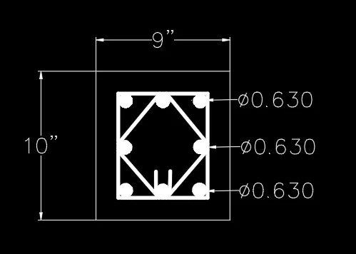
v) In given fig Column C2 a is provided with 8 bars of 16 mm dia . Size of column is 9" x 10" .
vi) Consider clear cover for column as 40 mm ( 1.5")
| Values in mm | Values in Inches |
| 12 | 0.473 |
| 16 | 0.630 |
| 20 | 0.787 |
Procedure -
i) Open a New autocad file (Cntrl N) in Imperical Units
ii) Change the Units to Engineering and Inches .
iii) Conver the diameter of bars into mm by dividing ( 25.4) .
Step 1) Detail of Reinforcement of Column C1
i) USe the Line tool As per given in note .
ii) Specify base point for rg (5,5)
iii) Specify next point (@9",0)
iv) Specify next point (@0 .24")
v) Specify next point (@-9",0)
vi) Close .
vii) Take the offset from all side as 1.5" (40 mm cover)
viii) Show the main reinforcement and longitudinal reinforcement as shown in fig .
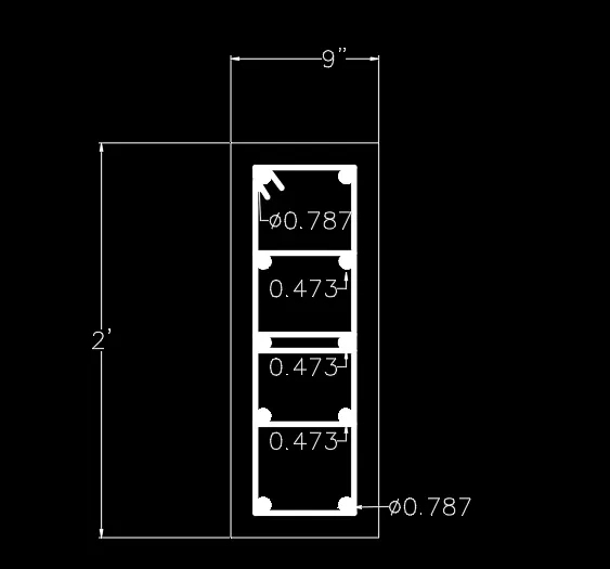
Step 2) Detail of Reinforcement of Column C1 a and C3 -
i) USe the Line tool As per given in note .
ii) Specify base point for rg (5,5)
iii) Specify next point (@9",0)
iv) Specify next point (@0 .24")
v) Specify next point (@-9",0)
vi) Close .
vii) Take the offset from all side as 1.5" (40 mm cover)
viii) Show the main reinforcement and longitudinal reinforcement as shown in fig . (12 - 16mm)
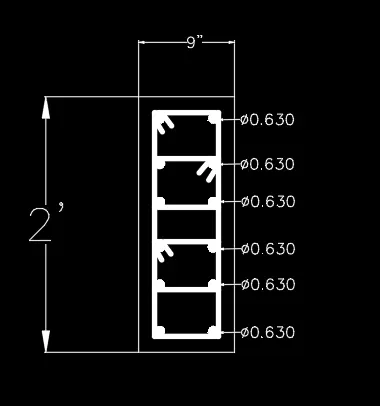
For C3 -
i) Repeat the same procedure
ii) Give the size as 9" x 21"
iii) No of bars will be same . (12 - 16mm)
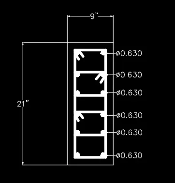
Step 3) Detail of Reinforcement of Column C2 -
i) USe the Line tool As per given in note .
ii) Specify base point for rg (5,5)
iii) Specify next point (@9",0)
iv) Specify next point (@0 .24")
v) Specify next point (@-9",0)
vi) Close .
vii) Take the offset from all side as 1.5" (40 mm cover)
viii) Show the main reinforcement and longitudinal reinforcement as shown in fig (4 - 12mm) and ( 8-20mm)
Step 4 ) Detail of Reinforcement of Column C2a -
i) USe the Line tool As per given in note .
ii) Specify base point for rg (5,5)
iii) Specify next point (@9",0)
iv) Specify next point (@0 .10")
v) Specify next point (@-9",0)
vi) Close .
vii) Take the offset from all side as 1.5" (40 mm cover)
viii) Show the main reinforcement and longitudinal reinforcement as shown in fig . (8 - 16mm)
Step 5) Make a chart as per given in fig .
i) Draw a table using line tool .
ii) Give Command DText .
iii) Select Font style Roman .shx
iv) Select Text hright - 8"
v) Justify - Left .
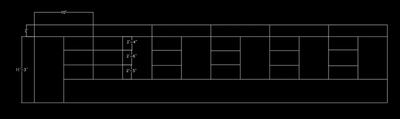
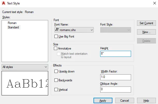
Draw a chart with the help of this settings .
Note - Scale the detail reinforcement of all columns to fit in the table
Command Scale - Specify base point and Give Scale factor 3.
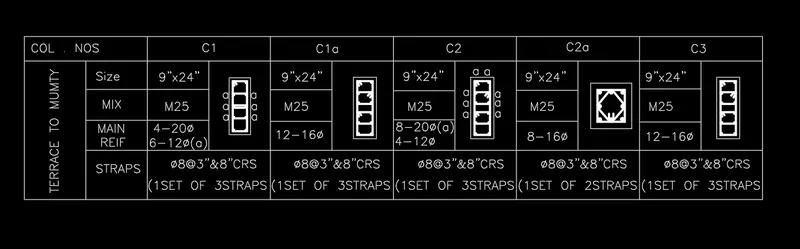
Results - Column Schedule is drawn as per given fig .
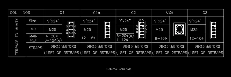
2)
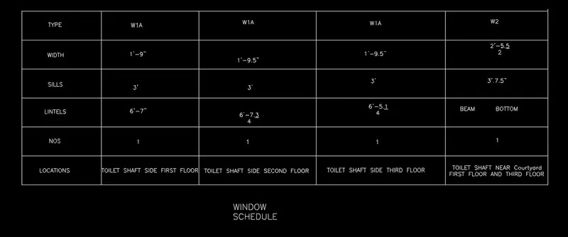
Aim - To create the Window Schedule
Introduction - i) The detail of window schedule is given .
ii) It contains the width of window , silt level , No of window and position of windows .
Procedure -
i) Open a New autocad file (Cntrl N) in Imperical Units
ii) Change the Units to Engineering and Inches .
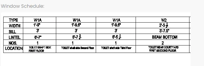
Step by Step procedure -
Step 1)
i) Give the command table .
ii) Select no of columns as = 5
iii) No of rows = 6
iv) Command DText .
iv) Select Font - Romans.shx
v) Text height = 8".
vi) Make the chart as per given figure .
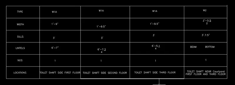
RESULTS - Window Schedule is drawn as per given in fig .
3)
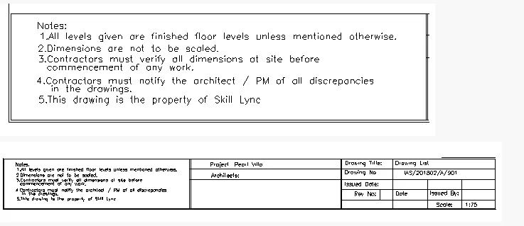
Aim - To draw the template as shown in fig .
Introduction - i) Template is given to identify whaterver notes given by architecture .
ii) In template profile like its name of the designer , address , Notes etc are given
Procedure -
i) Open a New autocad file (Cntrl N) in Imperical Units .
Step by Step procedure -
Step 1)
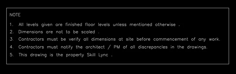
i) Command Multi Text
ii) Select font - Roman .shx
iii) Select text height = 10"
iv) Write a Note which is given in fig .
Step 2)
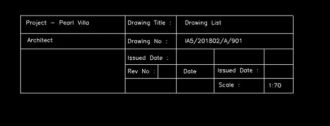
i) Make the remaining part of given fig .
ii) Make a table by using line command .
iii) Write the data as shown in fig .
iv) Select the font as Roman
v) Select text height = 10"
Step 3)
i) Join above two table by moving command .

Results - The given template is drawn as per given in fig
4)
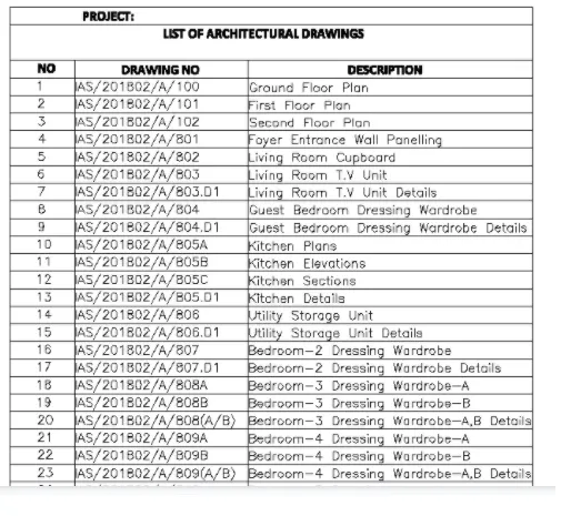
Aim - To create a list of drawing schedule .
Introduction - i) Detail List of drawinsgs is given in figure .
Procedure -
i) Open a New autocad file (Cntrl N) in Imperical Units .
Step by step Procedure -
Step 1)
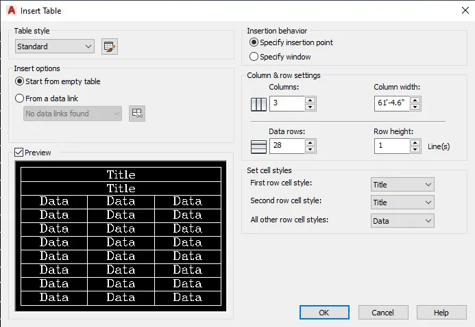
i) Create a table by giving command Table .
ii) Select a font style - Roman.shx
iii) Select text height = 8"
iv) Select no of columns =3
v) Select rows = 28
Step 2)
i) Enter the data as given in fig .
ii) Enter the Title and fill the data
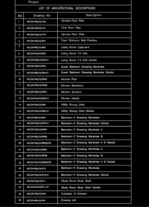
Results - The given List of drawings is drawn .
5)
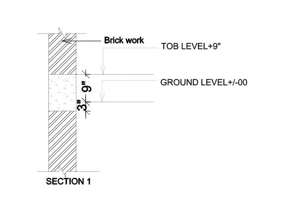
Aim - To create beam details as shown in figure .
Introduction - i) Details drawing of beam is given in figure .
Procedure -
i) Open a New autocad file (Cntrl N) in Imperical Units
ii) Change the Units to Engineering and Inches .
iii) Use relative coordinate system
Step by Step Procedure -
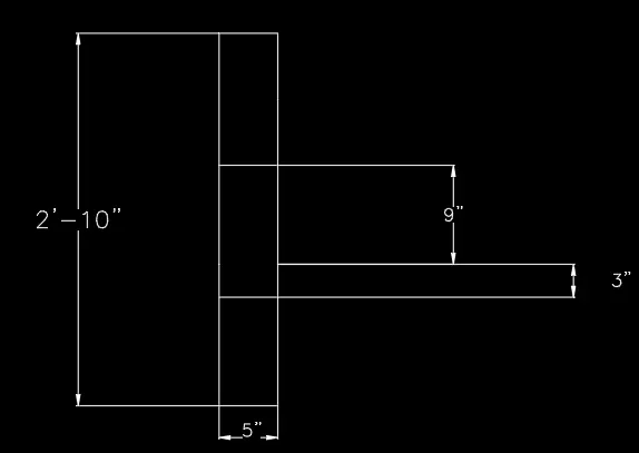
Step 1)
i) Give the command Line (L)
ii) Specify 1st point (1,1)
iii) Specify next point ( @1',0)
iv) Specify next point ( @0,1.5')
v) Draw offset of 3" from above point in positive y direction .
vi) Again draw offset of 9" from above point in positive y directions .
Step 2)
i) Use break line command and break the line at top and botom .
ii) Give the hatching by giving command Hatch . to shpw the brickwork
iii) Select Hatch - ANS134
iv) Select area and apply hatching command .
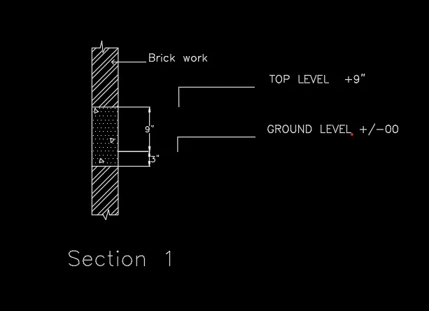
Results - The given beam details is drawn