Creation of Column Schedule and Drawing Template using AutoCad
1.Aim & Introduction:
Aim:
This challenge aims utilize the introduced advanced tools in the AutoCAD software in the different areas of the civil engineering industry. It gives the opportunity to provide detail drawings and specifications done in a civil project. These challenge aims to practice the challenger in the use of different text commands by utilizing the text and mtext tools in AutoCAD. The specifications of next height, width factor, text style, rotation of text and spacing consumptions are included in this challenge.
Introduction:
The AutoCAD software provides different tools. The tools used in this challenge is as described below:
Line- creates line object
Trim- Cut unwanted lines or shapes with the provided cutting edges
Move-move objects to particular locations
Copy-copy objects to particular locations
Dimlinear-Provides vertical or horizontal linear/ straight dimensions
Leader-Creates an arrowhead line
Units-Open "Drawing Units" WIndow to specify the drawings units
Dimstyle-Open "Dimension style Manager" window to modify the dimension properties
Dtext-Creates text object
Mtext-Creates a multiline text
Scale-scale objects to a specified percentage or length
Hatch-Creates hatch patterns in a selected objects or internal point
2. Sketch and Procedure:
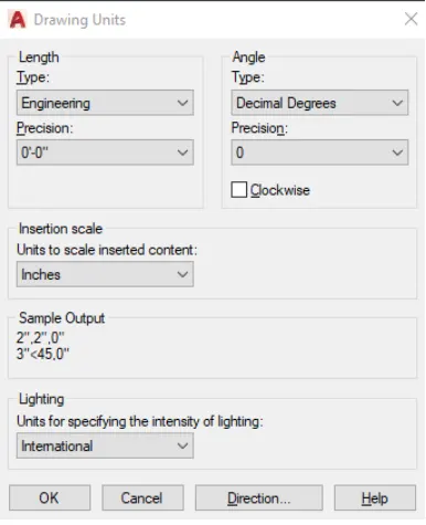
Most of the challenge are in english units. The Autocad units should be set to either inches or feet. The "Engineering" unit type is used in the challenge. To specify the units, "units" is typed in the command prompt so that the "Drawing Units" window will appear.
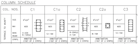
A.SKETCH 1- COLUMN SCHEDULE
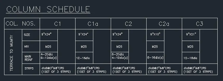
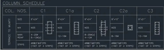
CHALLENGE 1- Create a column schedule as shown in the figure.
Note: Create a column schedule with the help of lines. Also, insert text with the help of Dtext command or single line text
Hint: Use font name: romans.shx: Height:8", Justify: Left
PROCEDURE:
Set Text Style:
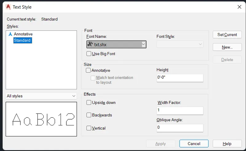
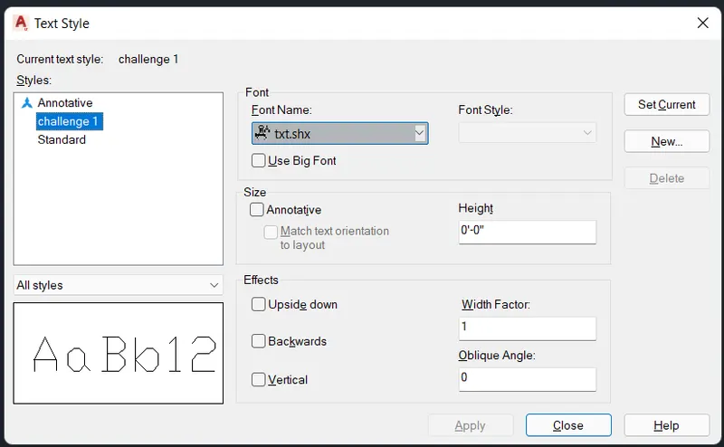
- First, set the text style and height using the syle comammd in AutoCAD. Type St in the command prompt. The "Text Style" window will appear
- Click "New" button to add a new text style. Specify the style name and press OK
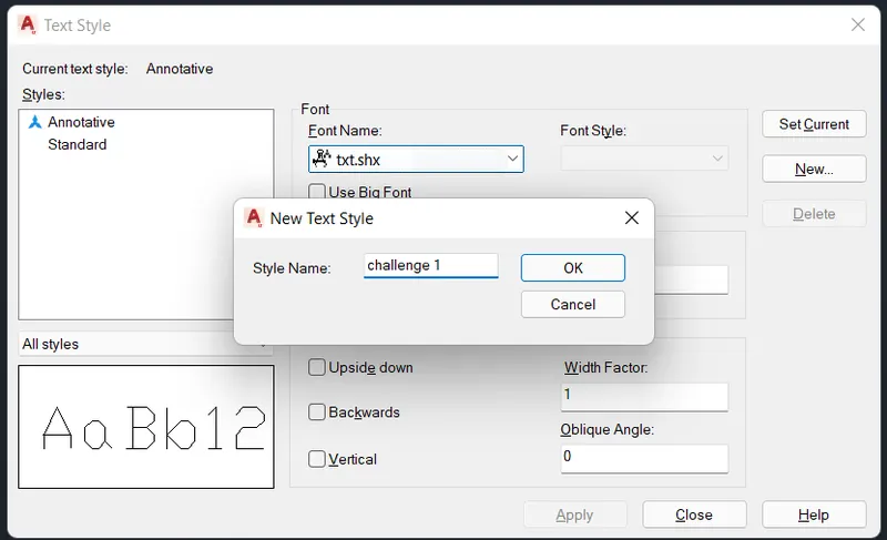
- Specify the font name and text height for standard size and style. Select the text style in the styles window and press "Set Current" button to activate the text style
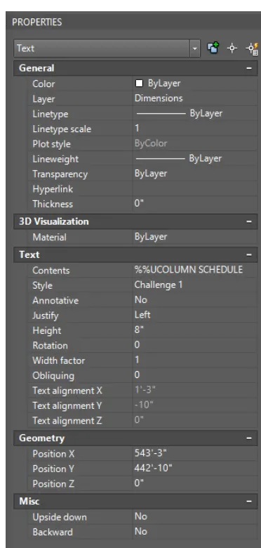
- To check the text justification, select any created text object and open the properties tab. This can be managed in the "justify"
Proceed with the column schedule:
Note: Dimensions used in the challenges for spacing of the boxes are approximate only. Adjustments ccan be made while creating the sketch to accommodate the spaces.
- Using the XLINE command, create a vertical and horizontal line.

- Use thefillet cemmand with radius 0 to make a corner.
- Select the offset tool. Specify offset distance to 48". select multiple to offset multiple times, create 5 horozontal lines downward
- Now for the vertical lines. Select the offset tool. Specify offset distance to 75". Select multiple to offset multiple times, create 4 vertical lines to the right.
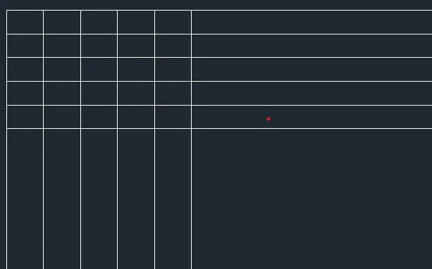
- Use the "Trim" command to delete excess lines. Select all as cutting edges. Follow the image below
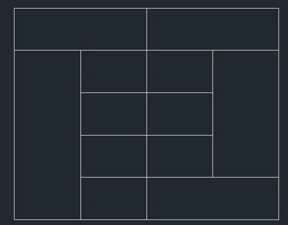
- Create the texts using the DTEXT command. Specify the base point at the lower left corner of the rectangle. Set rotation angle to 0. The text height need not be specified as the height of the text is alreadly set in the style. Move the text in the appropriate spaces. Cureent text height is 8".
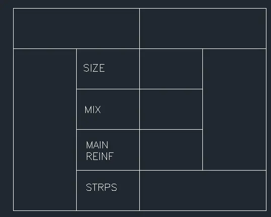
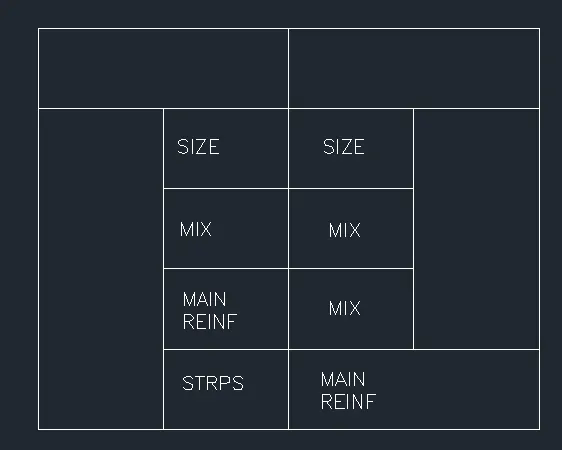
- Do the same on the right side. You can copy all the text from one position to another and change the content by double clicking the text. This will prompt the textedit mode.
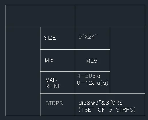
- Create the title of each column. select the DTEXT command and enter thecontent "COL.NOS" Use teh lower left corner of the rectangles as base points. The current text height is 8", use the scale tool to double the size of the text. To scale, use the"SCale" tool. Set the insertion points as the base points.
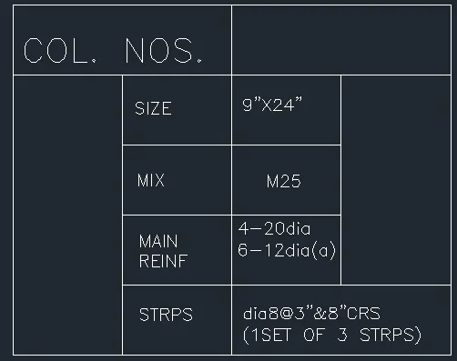
- To center the text, open the properties tab (it can be accessed by typing "Properties" in the command prompt) set the "Justify" option to "Middle"
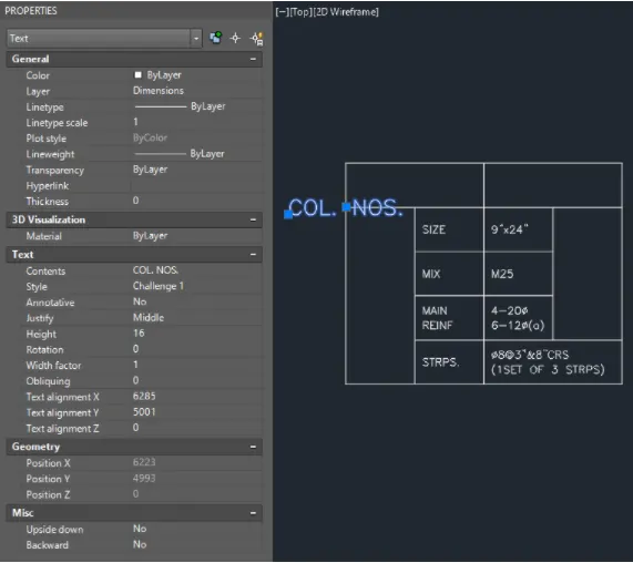
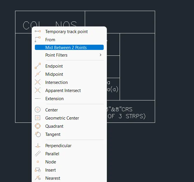
- Move the text to the middle of the space provided. Select the move tool. Specify the insertion point of the text as base point. When specifying teh econd point, click "Shift+Right click" and select "Mid between 2 points" . Select the corner points of the space provided to specify the center.
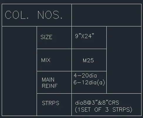
- Do this on the other Title text. To create the rotated text, select the DTEXT command. Specify the lower left corner of the whole rectangle as base points. Set the rotation angle as 90. Specify the content.
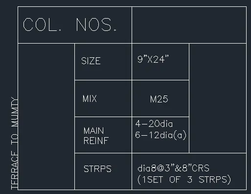
- Scale the text to 1.25 and move to the middle of the space provided. Then create the title for C1.
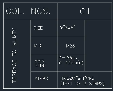
- Duplicate C1 detail and rename as C1a
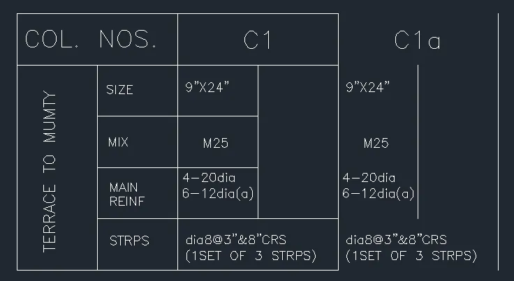
- Extend the lines using the extend tool. Use right most vertical line as boundary edges
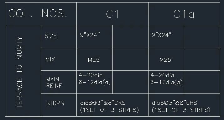
- Use the trim tool to delete the unnecessary lines. Replace the text content with the correct content as per the data.
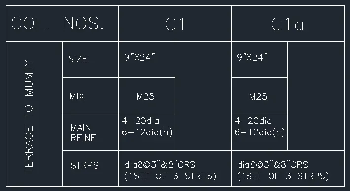
- Do the same steps until you reach the last rectangle
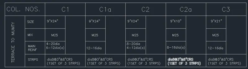
- Create the "Column Schedule" title. Select DTEXT command and set the upper left of the schedule as base point. Set rotaion angle to 0. Scale th text to 2.0 and move up by certain space. To make the underline, double click the text object to center the textedit mode. Once all text are selected, press CTRL+U to underlinethe text.
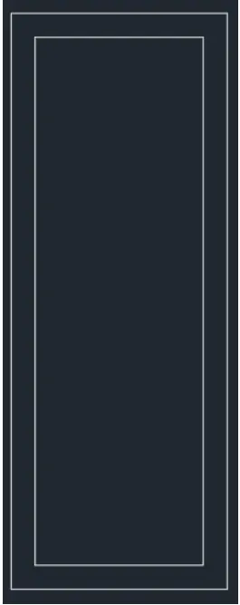
Create thecolumn details. Follow the dimesions given. Scale to 3x the original actual size to accommodate the spaced provided.
- Select the rectangle tool, specify the dimensions. Offset the rectangle inward to specify thr concrete cover and strirrups.
- Create circle with appropriate diameters to identify the rebars . Use the fillet tool to fillet the edges.
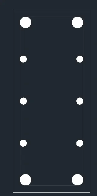
- Use th rectangle tool to identify the stirrups
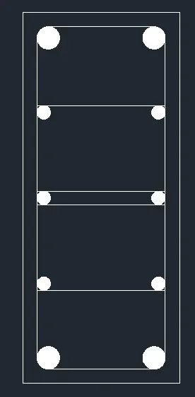
- Fillet the edges for better representation. Now create the hooks. The hoops can be created using the ellipse tool.
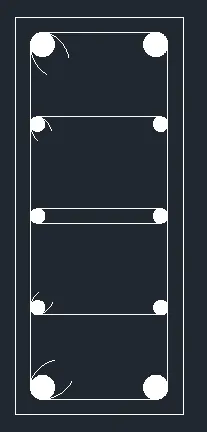
- The created column is the C1. select the whole object. Select the copy tool. When Specifying the base point, press CTRL+Right click, select the "Mid between 2 points" and specify the corners of the rectangle. For the second point, do the same procedure then specify the corner points of the spece provided as second point.
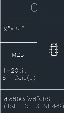
- Scale the object 3X its size using the scale tool. Specify the center of the object as base point. Add the "a" text to identify the different bar size.
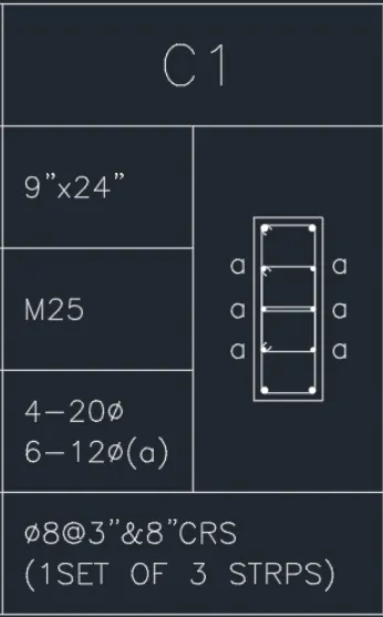
RESULT:
FINAL PRODUCT
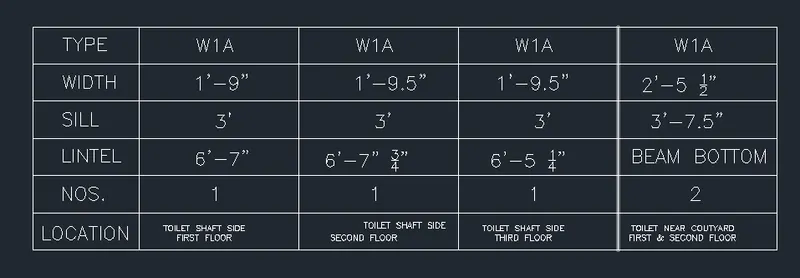
B.SKETCH 2- WINDOW SCHEDULE
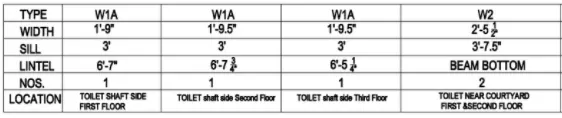
CHALLENGE 2- Create a window schedule as shown in the figures
- Using the XLINE command, create a vertical and horizontal line.
- Use the fillet tool to make the corners. Fillet radius is 0
- Offset the horizontal line downward 6 times at a certain space. Use the offset tool or copy tool
- Copy the vertical line horizontally to a desired space. Lets say 70units to the right. Use the copy tool or offset tool to do this
- After adding the line, trim theexcess vertical line at th bottom. Use the last line as cutting edges
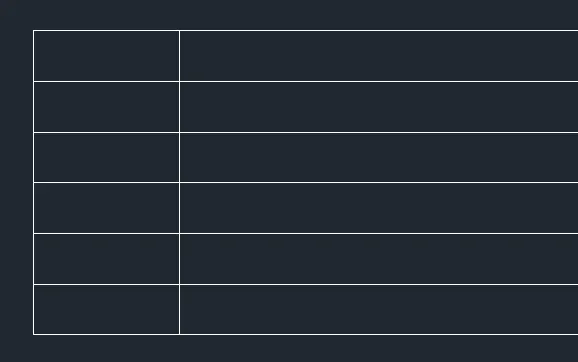
- Add a text at teh 1st rectangle using the text command. Change the justify to middle and center the text. Do this to compelete the text on the first column
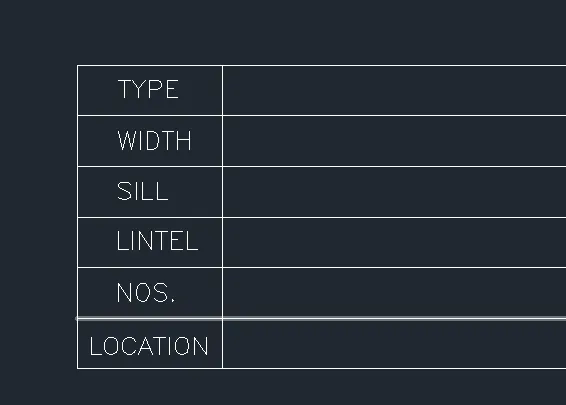
- Copy the rightmost vertical line to right in a desired space. Lets say 100units
- Add the text on the second except on the last row. use the dtext command. You can also copy the text on the first row to maintain the same alignment
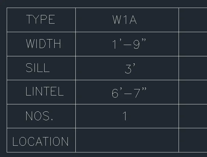
- For the text on the last row, create a text using the lower left corner as the base point. Type the content "First Floor". Scale the text object by 2/3 or 0.6666 to make it smaller. Justify used is left
- Move the text object by 4 units upward. Move those 2 objects 8units to the right or at a desired space.
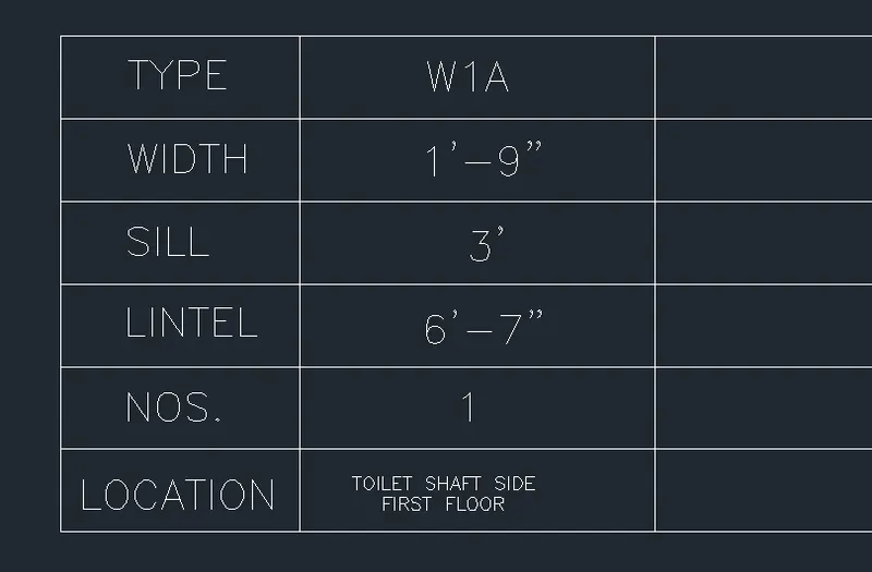
- Copy the text on the 2nd row 3 times to the ight using the copy tool. Use the upper most left corner of teh 2nd row as base point and use the upper right corner as second point.
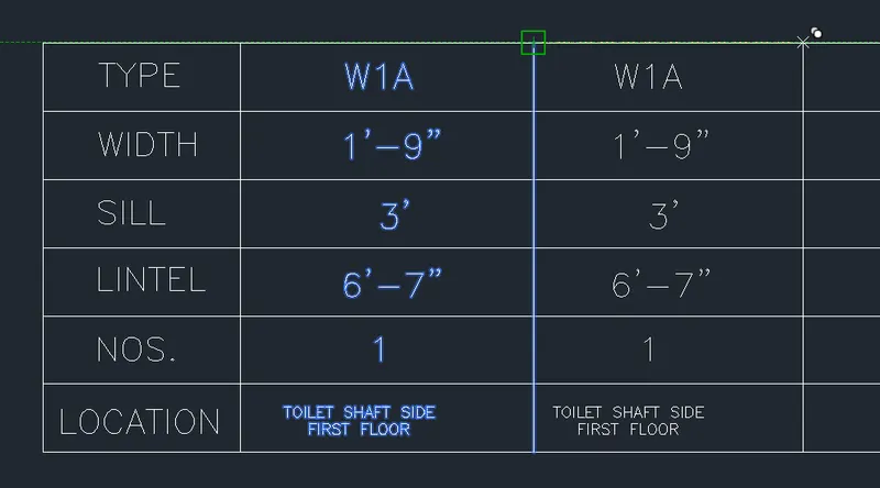
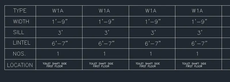
- Trim the excess horizontal lines using the right most vertical line as a cutting edge. You can always create new columns by coping text object and vertical line object to the right then extending the horizontal lines
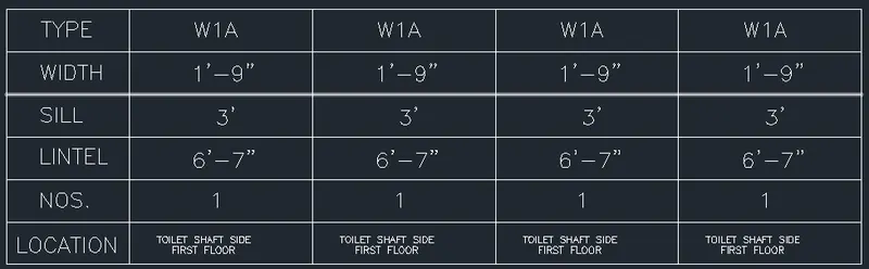
- Double click thetext to enter textedit mode and change the text content to the correct one
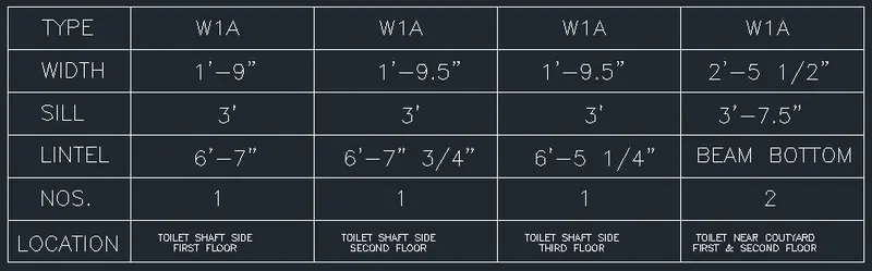
- Notice that there are text outside the box and the fraction is not the same as the image. To revise the text going outside the space provided, change the justify to fit. Open the properties tab. Select the text object and change the justify option to fit. Grip the text inside the provided space.
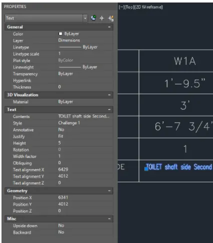
- Do these for the other texts
- DO change the fraction image, change the text object into a MTEXT object. Select the TXT2MTXT command and select the desired text
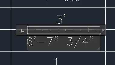
- Select the fraction text and select the STACK option in the MTEXT Editor
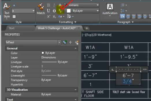
- The text will look like the image below. Do this for the other texts
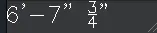
RESULTS:
FINAL PRODUCT:
C. SKETCH 3- DRAWING TEMPLATE:
CHALLENGE 3- Create the drawing template as shown in the figure. Use the notes as in the figure
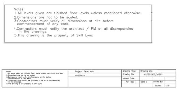
PROCEDURE:
- Create the border using the XLINE command. one vertical line and one horizontal line

- Fillet the corner and copy teh horizontal line below to a desired space. THis can ne adjustable later. Radius of fillet is zero.

- Create a text using the MTEXT command. Write the content on the first column as paragraph. The MTEXT command allows you to do this like a word file
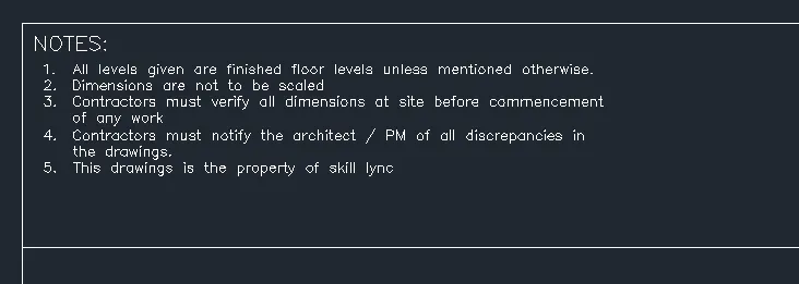
- Position the created text to a desired location. Use the move tool
- Position the bottom horizontal line to accomodate the space desired and trim the excess vertical line afterwords
- Copy the trimmed vertical line to the right enclosing the text
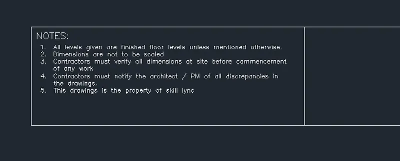
- Divide the right most space into 5equal spaces. To do this, either measure the distance between the lines and divide by 5 or divide the line by 5 using the divide command
- Using the distance command, measure the vertical line
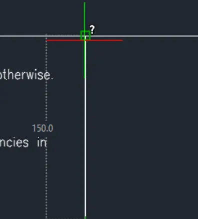
- the space will be divided into 5 so 150/5 spaces is 30 units. Copy theupper vertical line downward by 30units you create the 4 lines
- trim the extended lines on the left using the vertical line as cuttingedges
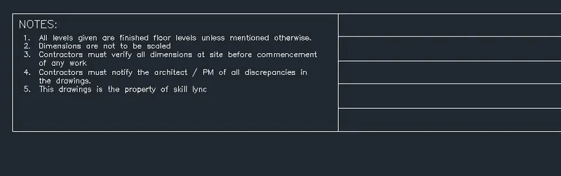
- Create the text on the second column using the dtext command
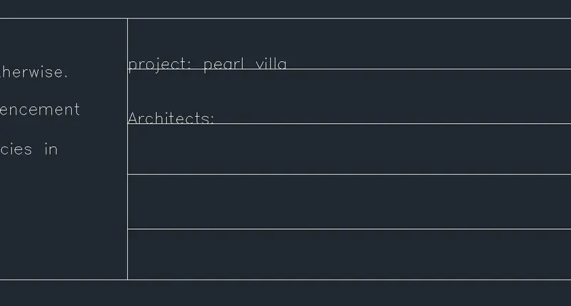
- Move it to the desired location within the given space and use the sacle command to increase the size to correct height within teh given space. You can alsojust simple change teh text height at the properties tab to control the size of teh text
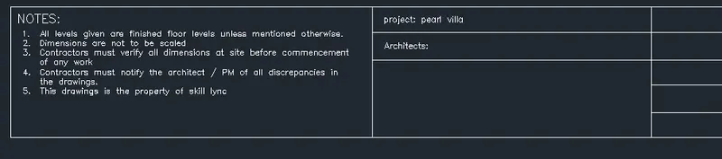
- Copy the vertical line to right and trim the unnecessary horizontal lines to the left
- Open the text style window by typing style on the command prompt. Use the properties of the created text on th second column so that creating texts for the other columns does not require to change its size
- Current text height is 12units, width factor is 0.8
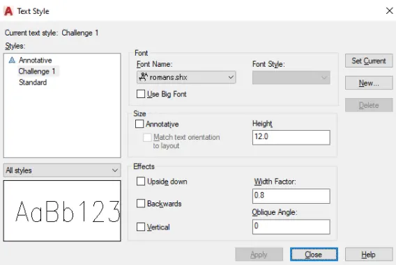
- Creat the text on the 3rd column using the dtext command
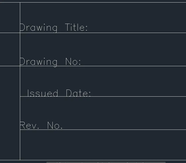
- Move the text to the desired location within the space using the move tool
- The n, copy the vertical line twice to the right to enclose the texts
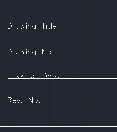
- trim the unnecessary lines using the trim tool
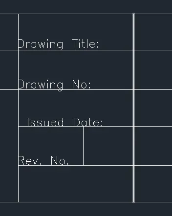
- Create the text on the first 2 rows of the last column using the DTEXT command. Use teh lower left corner of the row as base point
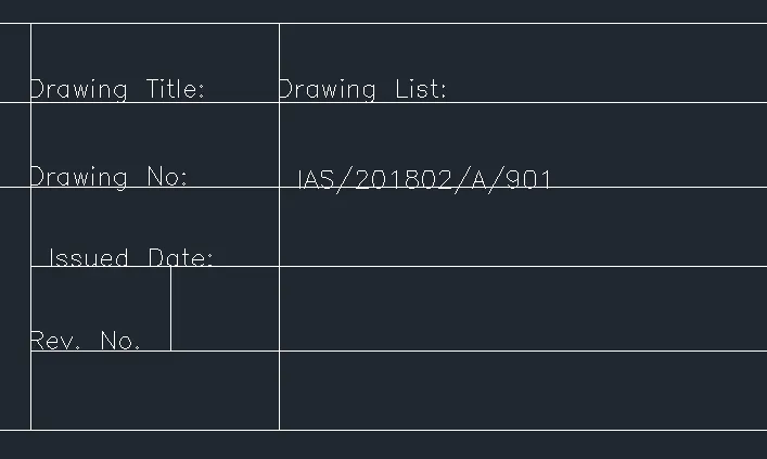
- Move it to desired location using the move tool
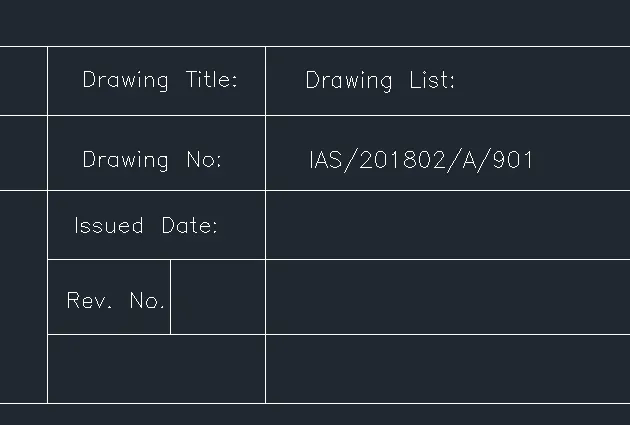
- Create the text "Date" on the fourth row. Use the DTEXT command. The n move it to the desired location within th row
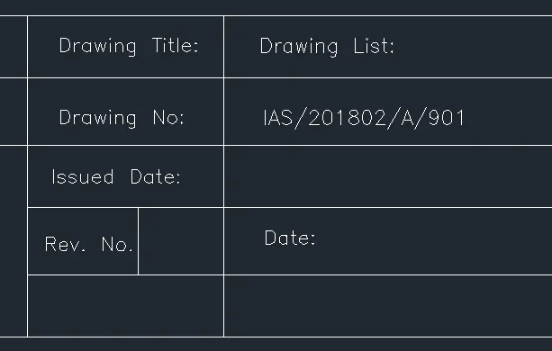
- Enclose the fourth row by copying the vertical line to the right use the trim tool to cut the vertical line within the 1st and 2nd row
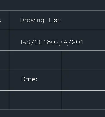
- Copy the created vertical line twice to the right, Ti make it equal, use the lower left corner as base point and the endpoint of the created vertical line as second point.Do this twice using the copy tool.
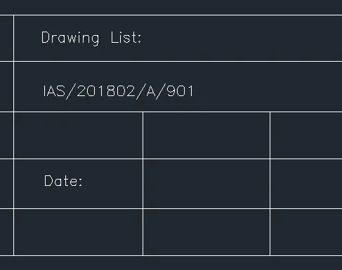
- Extend the last vertical line to the top most line
- then trim the excess horizontal line to right
RESULTS:
FINAL PRODUCT:

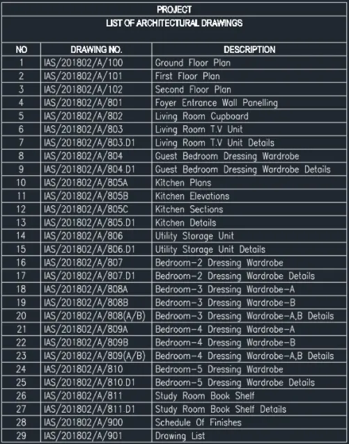
D. SKETCH 4- LIST OF ARCHITECTURAL DRAWINGS
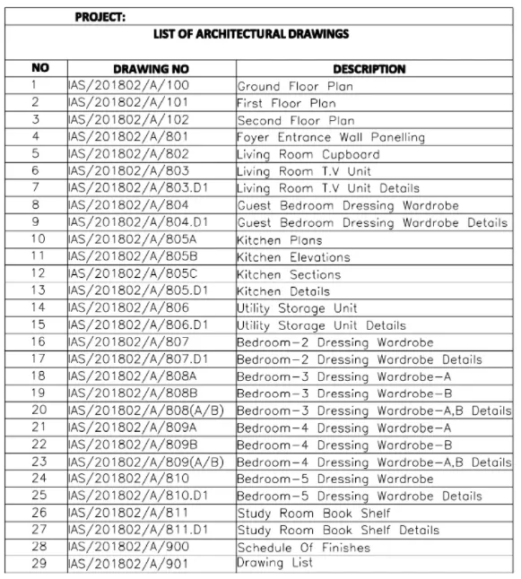
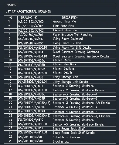
CHALLENG 4- Create the list of drawing schedule as shown in the figure
PROCEDURE:
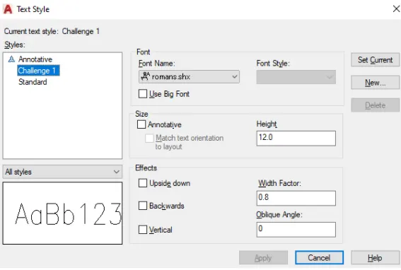
Text height used is 12units. Justify is left align. To set this settings, open the text style window using the ST(STYLE) command. Text style name is challenge 1. For the title texts, text style "Title is created with a different font name. Font style is Arial. Other properties are the same
- Create the border line using the Xline command
- Fillet the corners using the fillet command. Use radius=0
- Copy the horizontal line 24units downward to accommodate the text height
- Create the text on the first row using the dtext command. Use the start point of the 2nd line as base point

- Move the text 6 units upward to center the text
- Offset the bottom horizontal line 33times downward.specify offset distance as 24units. Select the Multiple option and offset away until you get 33 horizontal lines
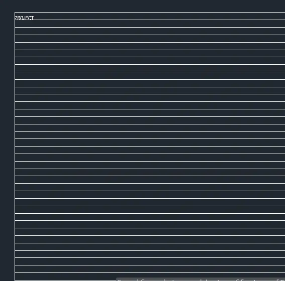
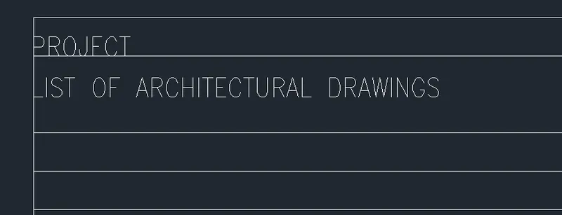
- Create the text on the 2nd row (LIST OF ARCHITECTURAL DRAWINGS). Use the start pint of the 3rd line as base point position it in the 2nd row and delete the 3rd line
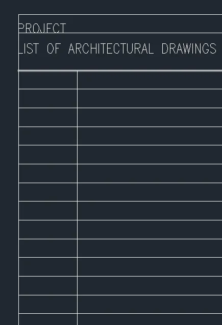
- Create the 1st column. Copy the vertical line to any desired units and trim the excess vertical line on top
- Create the txt on first row on the first column. Use the dtext command
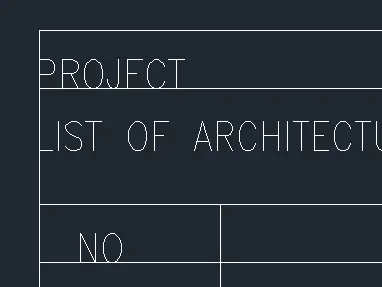
- Open the properties tab and set justify option of the created text (NO) to middle. position it on middle of the cell. use the "Mid between two points" when moving the text
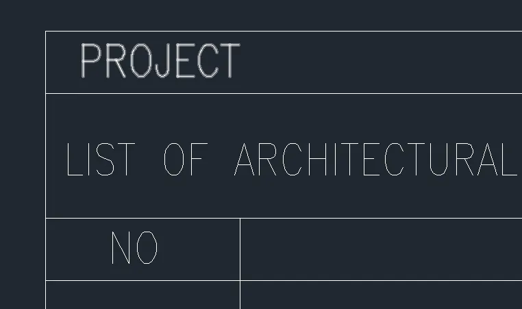
- Create all txt in the first row on the first column using the dtext command.Use the same procedure with the text "NO"
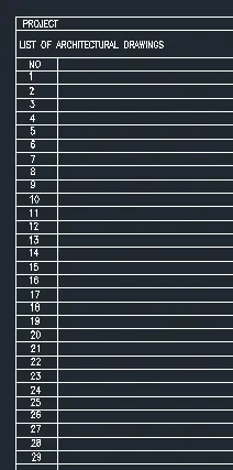
- Trim the excess vertical line at the bottom
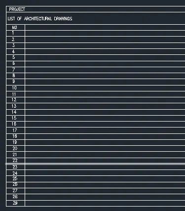
- Create the second column by copying the 2nd vertical line to the right. Distance are as per desired. This line can be adjusted as you create the text.
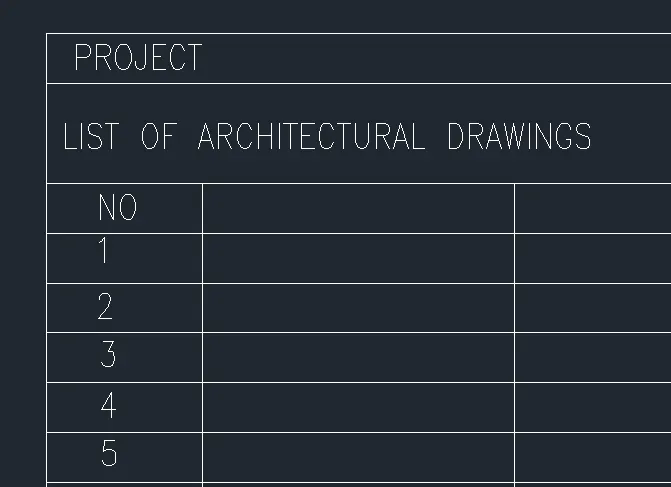
- Create the text for 2nd column. Start on the 2nd row so the vertical line can be adjusted afterwards. Use justify=left. Move the text 6units upward to create the text in the cell. Move all the text 6units to the right and finalize the position of the 3rd vertical line
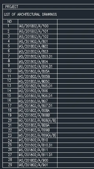
- Add the title text for teh 2nd column. Use lower left corners as base points. Change the text justify to "Middle " then move it to the center align using the "mid between two point" option.
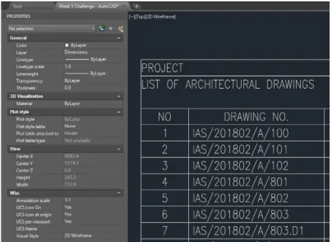
- Do the same procedure for the third column. first create teh texts fom the 2nd row. Move 6units up nad 6units right then finalize the location of last vertical line by copying the vertical line on the left to the desired position on the right
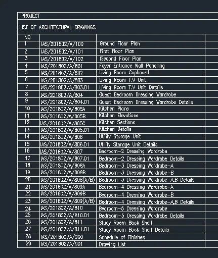
- Create the title texxt of the 3rd column using the dtext command. Use the lower left corner as the base point. set justify to middle. The n move to the center of the cell using the "Mid between two point" option
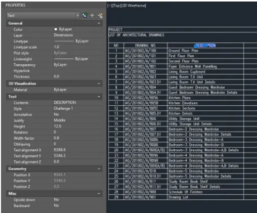
- Fillet the rightmost vertical line and topmost horizontal line to enclose the boundary. a=Fillet radius should be 0
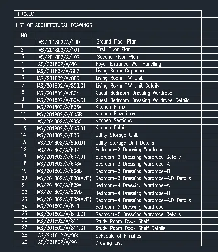
- Trim the excess horizontal line outside the border line. Use the rightmost vertical line as cutting edge
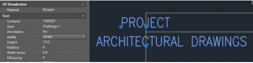
- Center the title text above. select teh text, change teh justify to center on the properties tab
- Move the text to the cenyter of the cell. Specify the start point of the upper line as base point and the midpoint of the line as second point
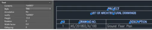
- Change the text style of teh tiltle text in the properties tab. USe the "Title" text style specified above
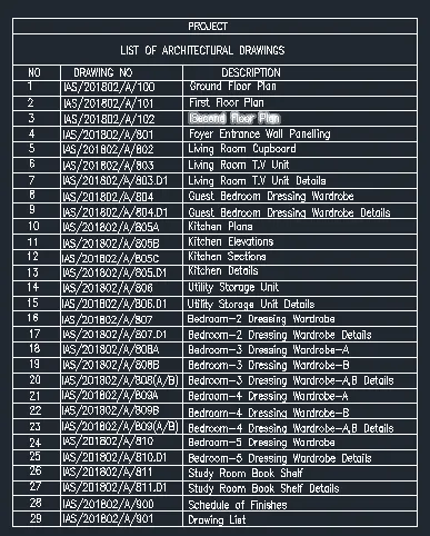
RESULTS:
FINAL PRODUCT:
5. SKETCH 5- BEAM DETAIL
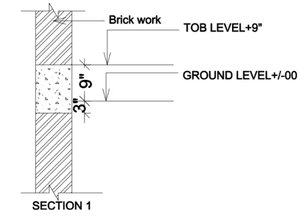
CHALLENGE 5- create the beam detail as shown in the figure and provide text whenever given
PROCEDURE:
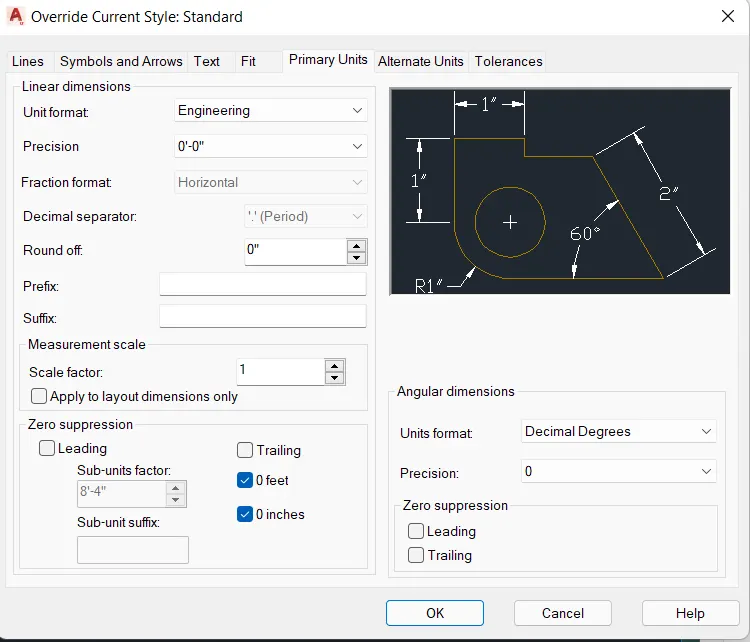
Engineering units are used in this challenge. Modify the dimension style in the dimension style manager. Open the dimension style manager by typing dimstyle in the command prompt. Select modify at the selected dimension to edit the style
note: some dimensions are assumed
- Craete 2 vertical line with any distance spaced at 12" (1')
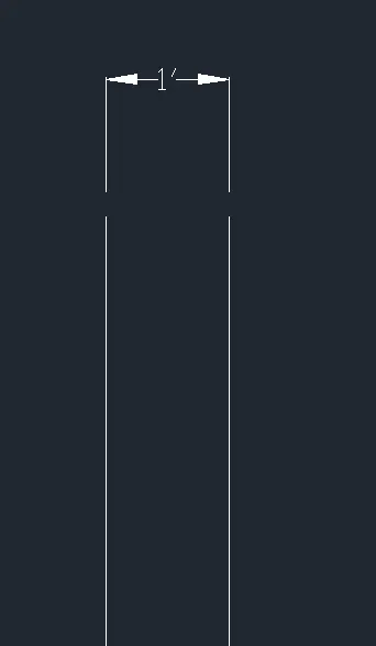
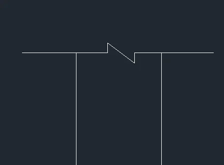
- Enclose the top part of teh vertical lines by creating a enclosemenet symbol. Use teh line tool
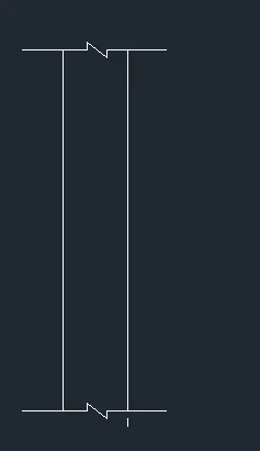
- Copy the symbol to the bottom part
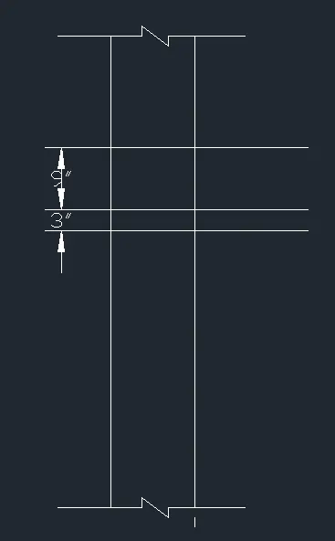
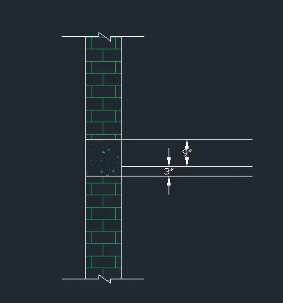
- Create 3 horizontal lines at any lenght using teh line tool spaced at 9" and 3"
- Trim teh lines at teh unnecessary locations
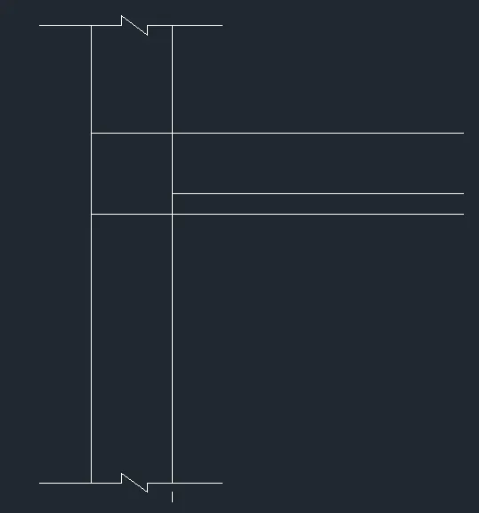
- Move teh horizontal lines around the center location
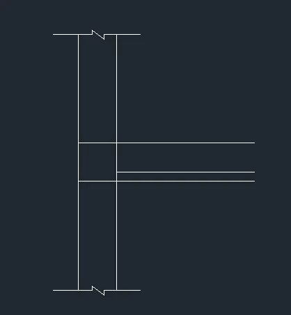
- Provide the hatching for the drawing. Select option by typing "Hatch" in the command prompt

- Select "Pick internal points" and select teh upper most space
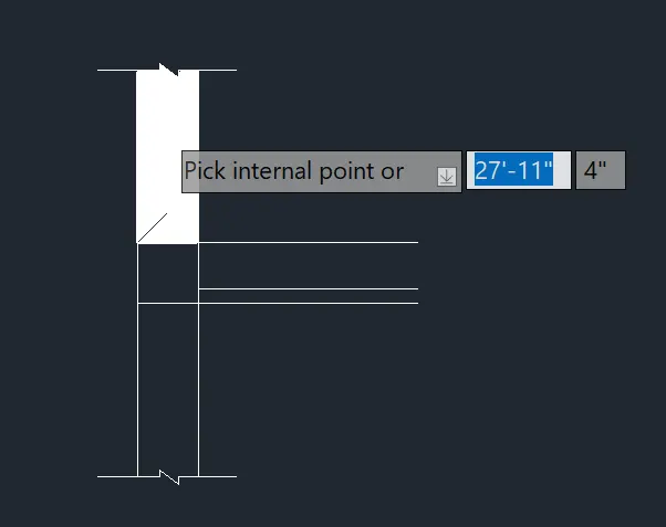
- Do this again for the other twi spaces. You should have three separate hatches
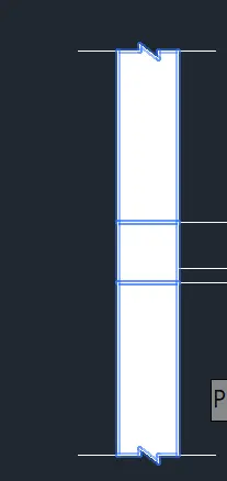
- Change the hatch style by selecting teh hatch and editing on the tool bars above the AutoCAD interface

- Change the pattern accordingly to the sketch. Select teh hatch pattern and select from there
- Hatch pattern used- Brick and Ar-Conc
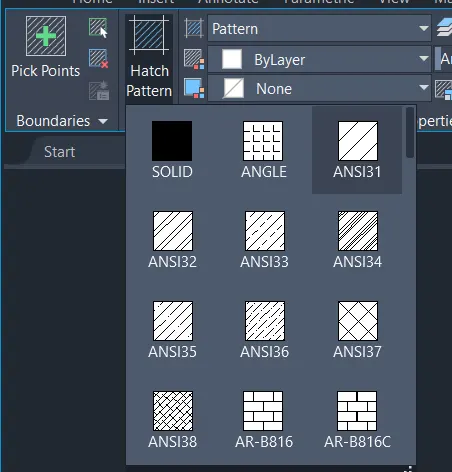
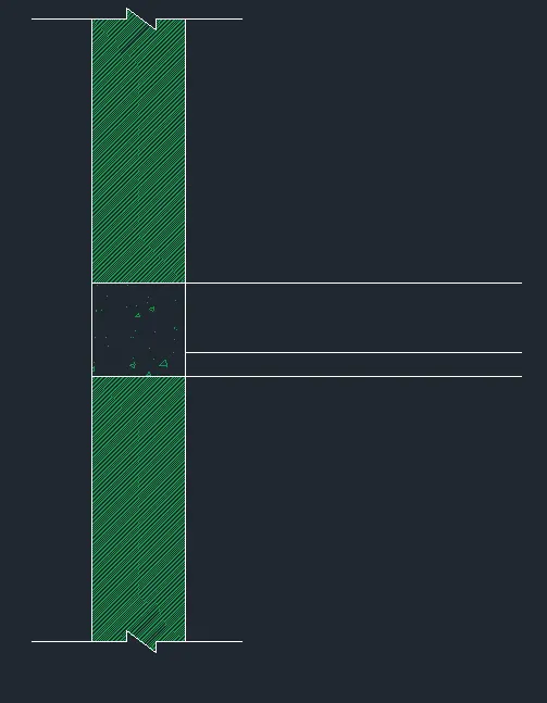
- Open teh properties tab to change teh scale of the hatch for a better view
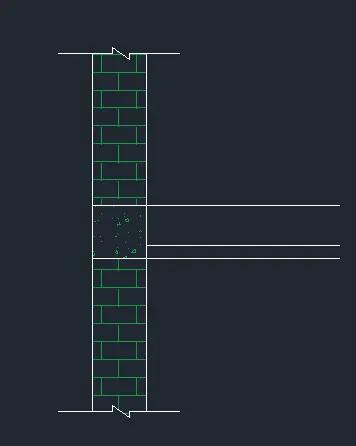
- Use teh dimlinear command to add the dimensions of the sketch
- Stretch the the top part and lower part of the sketch inward for better view
- Select teh bottom part of the text using the green selection
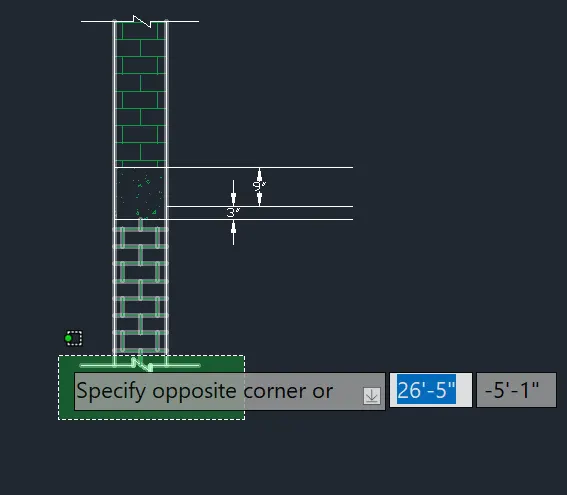
- Add the text for the the ground level. Select theleader tool. Create a leader line at the appropriate location
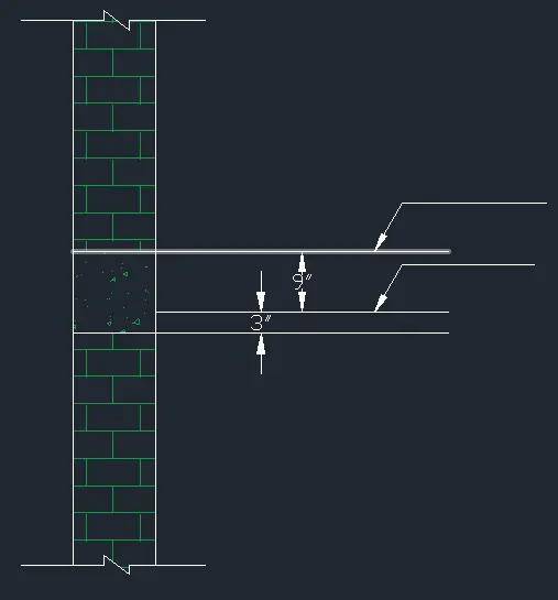
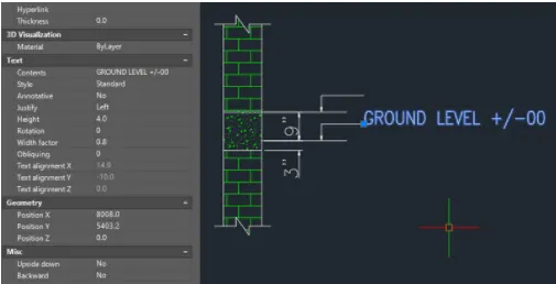
- Add the text using the dtext command. Use the end of the leader line as base point. Text height is 4. Justify is left and width factor is 0.8 and ad text "Brick work" using the dtext command
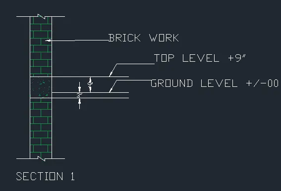
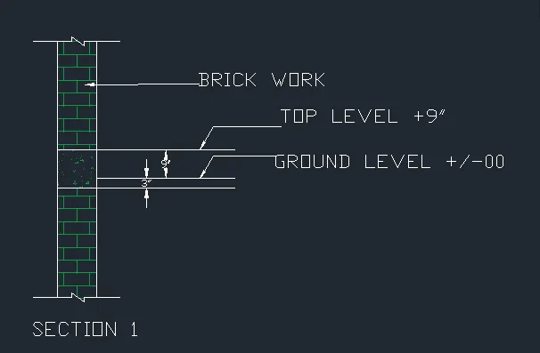
RESULTS:
FINAL PRODUCT:
3.CONCLUSION:
The AutoCAD software provides a complete interface where the user can sketch a given object as well as described it or identity its part using the text command and other annotations. The AutoCAD software does not allow the user to only sketch the given object but also provide measurements needed to understand the object. By describing the object using texts, the civil drawing will be more understandable and specifications can be identification in all the drawings.