Creating various 3D Models like Furniture, Footing, Girder, Column drop with panel and Gable Wall in AutoCad
1. Create a 3D Furniture element as shown in the Figure. Assume dimensions which are missing.
AIM: To create 3D model and view of:
- Furniture element
- Isolated footing
- AASTHO type girder
- Drop column with panel
- A wall
Commands used:
- Extrude.
- Offset.
- UCS.
- Box.
- Union.
- Subtract.
- Move.
- 3d orbit.
- Loft.
- Sweep.
- Cone.
- Region.
- Boundary.
PROCEDURE:
Open the AutoCAD, click on workspace switching and change it to 3d modelling and click on the home button near the view cube.Set the limits and zoom - all.
1. Create a 3D Furniture element as shown in the Figure. Assume dimensions that are missing.
Aim
To create a 3D furniture element as shown in the figure:
Procedure:
- Initially open the AutoCAD and go to 3D modelling in the settings and change the wokspace to 3D modelling.
- Now set the units as Engineering (feet and inches).
- Then set the limits of the drawing
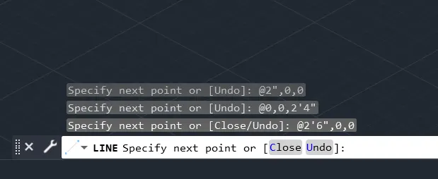
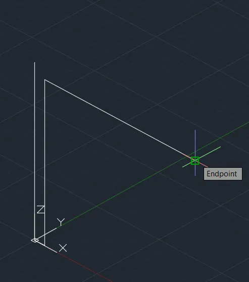

- Now, using line command draw the box structure:
- Specify the first point : 0',0',0'
- Specify the next point: @0',0',2'6"
- Specify the next point: @0',3',0'
- Specify the next point: @0',0',-2'6"
- Then close it.
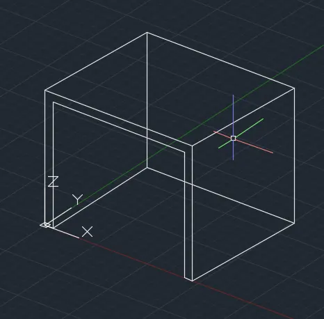

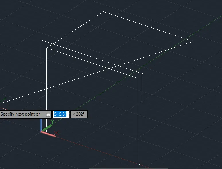
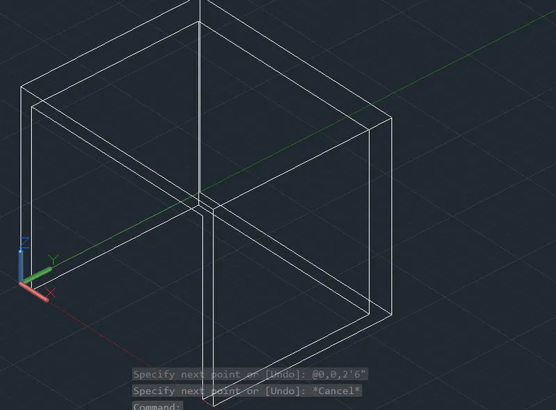
- Now, make it hidden.
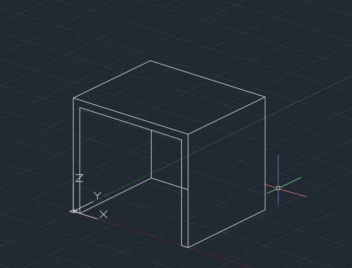
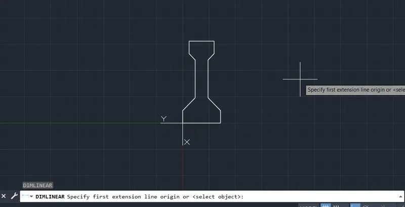
- Now, using dimlin command dimensioning is done to complete the object.
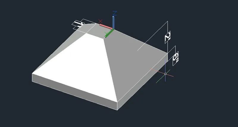
2. Create the 3d Model of an Isolated footing as shown in Figure.
Aim:
To create the 3D model of an isolated footing as shown below:
Procedure:
- Initially open the AutoCAD and go to 3D modelling in the settings and change the wokspace to 3D modelling.
- Now set the units as Engineering (feet and inches).
- Then set the limits of the drawing:
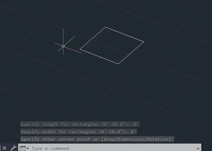
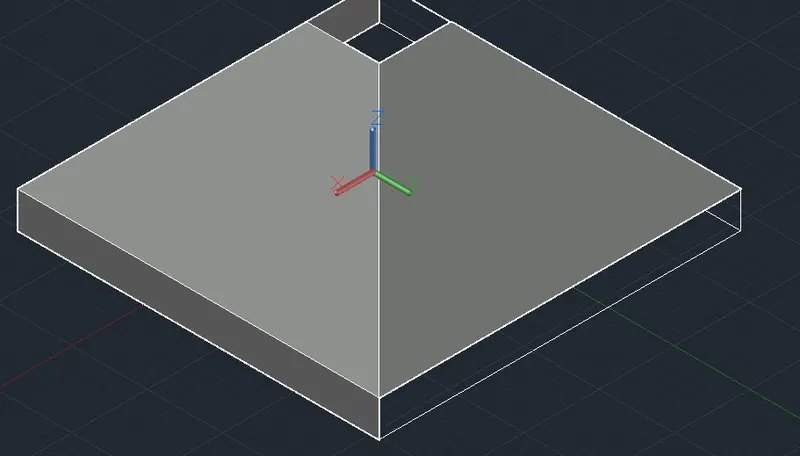
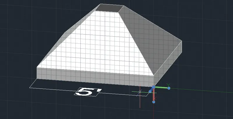
- Now again choose line command and draw a rectangle at the bottom of the tapered section and then convert it to a region.
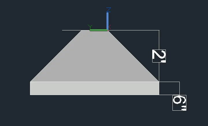
- Then extrude the rectangle downwards at a depth of 6".
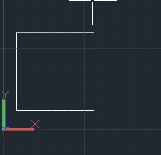
- Choose the line command and draw a square of side 1'.
- Then, convert it into a region and then extrude it downwards at a depth of 2' with tapering angle of 45 degrees.
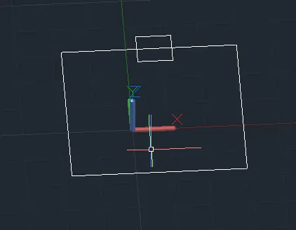
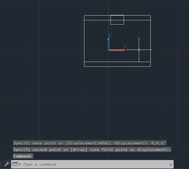
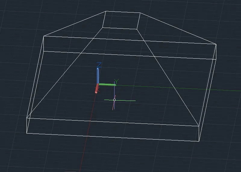
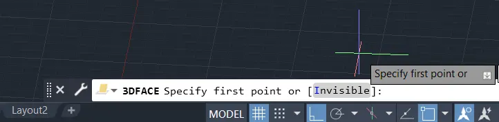
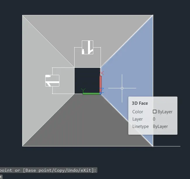
- Using 3Dface command give proper face component to the drawing.
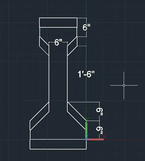
- After completion of drawing, give proper dimensions using the UCS and Dim command.
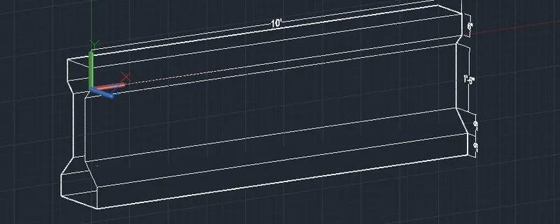
3. Create the 3D view of the AASTHO Type Girder.
Aim:
To create the 3D view of the AASTHO type girder
Procedure:
- Initially open the AutoCAD and go to 3D modelling in the settings and change the wokspace to 3D modelling.
- Now set the units as Engineering (feet and inches).
- Then set the limits of the drawing:
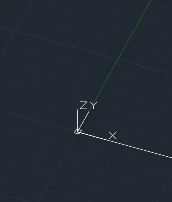
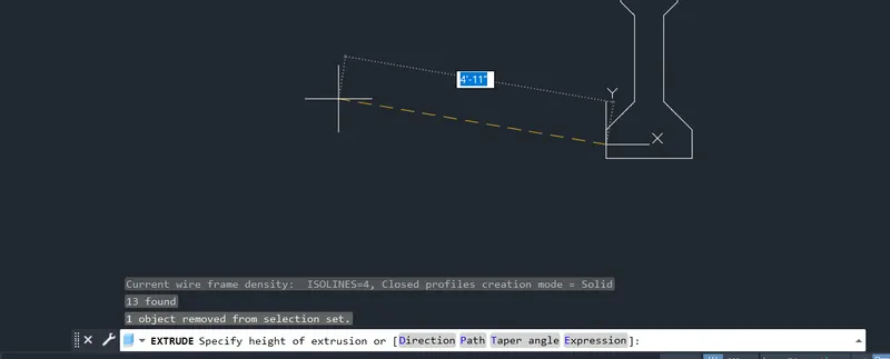
- Now using the line command drawn an I section as given in the question:
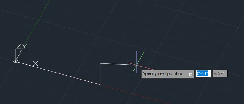
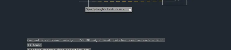
- Now, convert this figure to a region so that it can be extruded.
- Then the figure is extruded at height of 10'.
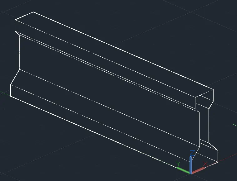
- Now, make the visibility to hidden.
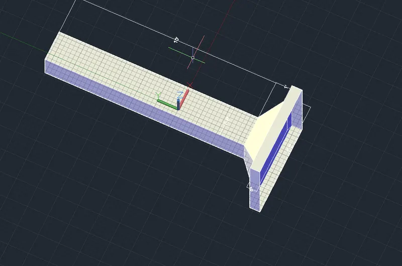
4. Create a 3d Model of a drop column with panel as shown in section and isometric view.
Aim:
To create a 3D model of a drop column with panel as shown in the section and isometric view:
- Initially open the AutoCAD and go to 3D modelling in the settings and change the wokspace to 3D modelling.
- Now set the units as Engineering (feet and inches).
- Then set the limits of the drawing:
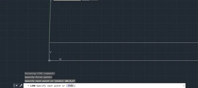
- Initially in the 3D modelling window, a square having side of 4'6" is constructed in the SW view.
- It is then converted to a region and is extruded at an extrusion height of 6".
- Then it is changed to hidden.
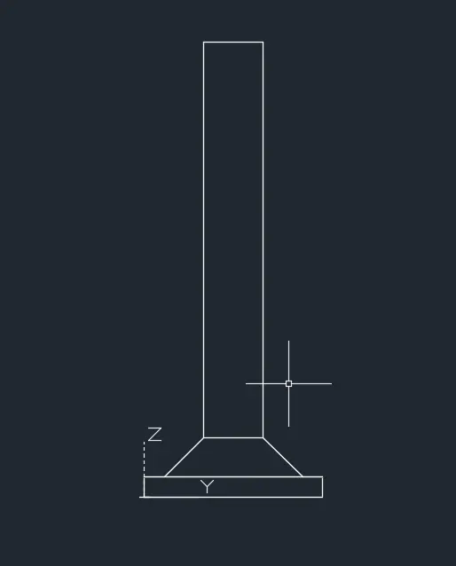
- Explode the tapered portion and the top circle is converted to a region and is then extruded at an extrusion height of 10'.
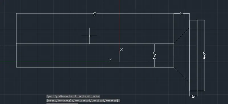
- Now, in the command prompt type 3D orbit and change its view conveniently.
5. Create the 3d model of a wall as shown in Figure. Consider wall thickness as 9”.
Aim:
To create 3D model of a wall as shown in figure:
Procedure:
- Initially open the AutoCAD and go to 3D modelling in the settings and change the wokspace to 3D modelling.
- Now set the units as Engineering (feet and inches).
- Then set the limits of the drawing:
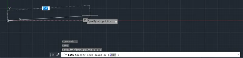
Step 1:
Draw a rectangle of 10' x 9".Create a line in the center and offset 1.5" on both sides as 3" is the width of door opening.
Step 2:
Use the command "BO" for boundary and create the region i.e., both the region on either side of the door opening.
Step 3: Extrude the region to a height of 12'6" total height.
Step 4:Create a rectangle in place of door in the top view.Move the rectangle in z axis at a height of 7' from the bottom
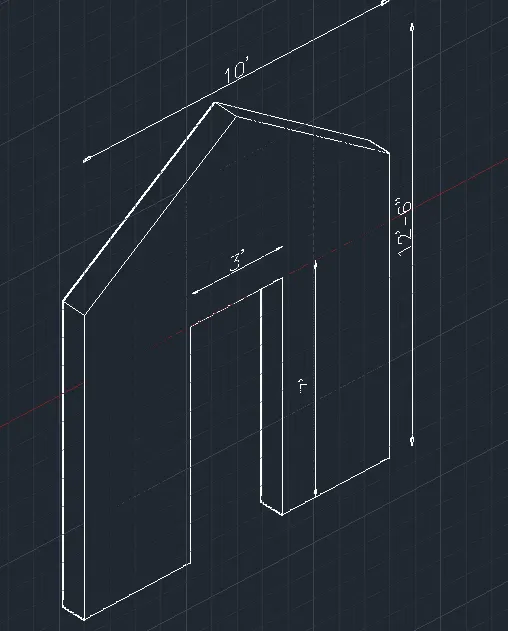
- Now, dimensioning is done with the help of UCS origin option.
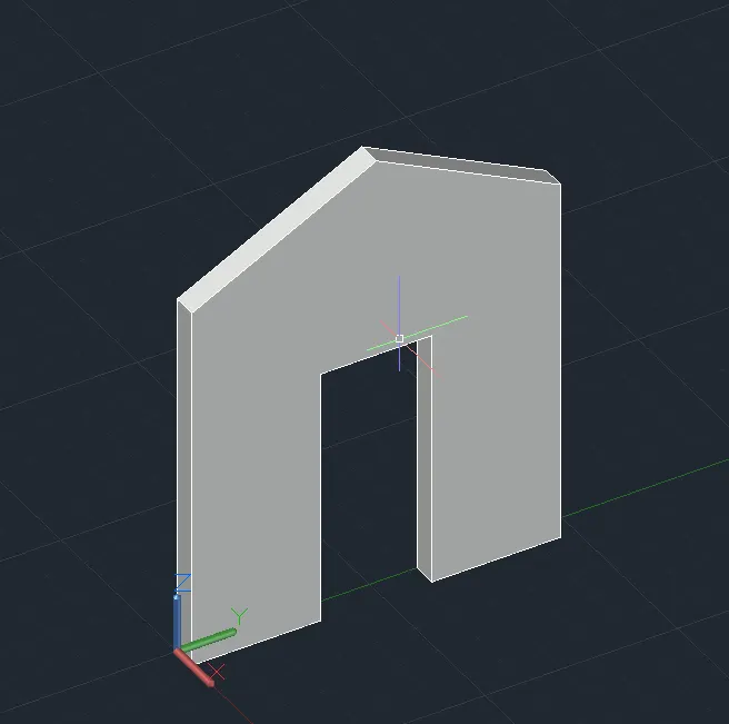
RESULT:
All the drawings are drawn using the proper commands and with the given specifications. Mainly 3Dface, ucs and 3Dorbit is used in this drawing to technically specify the different components in the drawing.