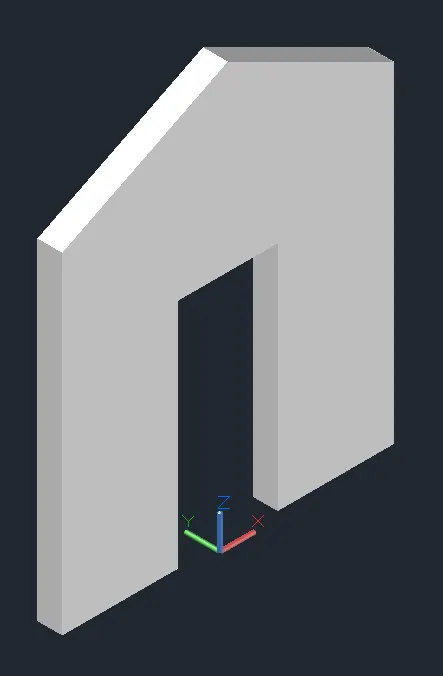
Creating various 3D Models like Furniture, Footing, Girder, Column drop with panel and Gable Wall in AutoCad
AIM:
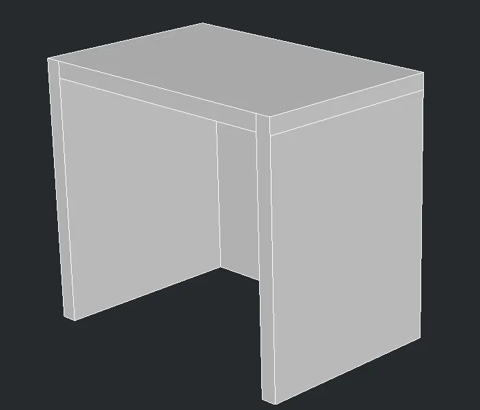
To Create a 3D Furniture element using 3d modelling in autocad.
PROCEDURE:
- To create a new sheet from application of Auto CAD.
- Go to the setting and to change the view of the page from Drafting to 3D modeling.
- Type UN to set the units of current format of measure.( feet and inches).
- Type LIMITS to set the maximum dimension limits on the particular page.
- First we take the top view of the page.
- Type REC to create a rectangle with a dimension of 2’0” x 3’0”.
- And then we take to a 3D custom view.
- To cretae the Z direction of 2'6" of both side of the table leg and add the thickness also 2" thick.
- Type extrude to create a surface or solid of a 2D surface.
- Then, we have to change the view of 2D Wire, Shaded, Conceptional,,etc.
RESULTS:
The diagram of 3D furniture elements is drawn as per dimensions using the software of Auto.
DIAGRAM:
AIM:
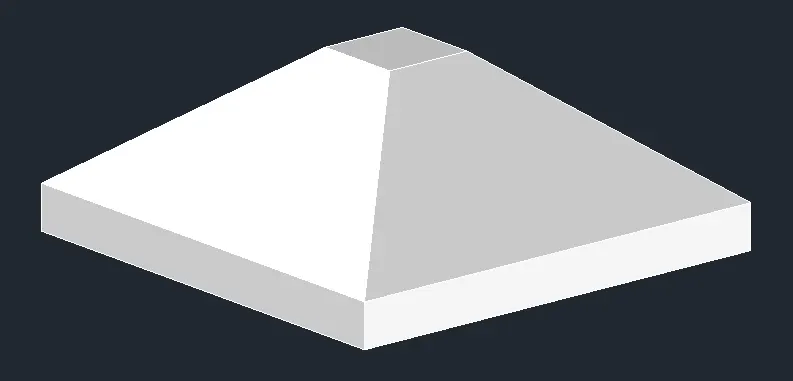
To create a 3D Model of an isolated footings using the various commands in Auto CAD
PROCEDURE:
- To create a new sheet from application of Auto CAD.
- Go to the setting and to change the view of the page from Drafting to 3D modeling.
- Type UN to set the units of current format of measure.( feet and inches).
- Type LIMITS to set the maximum dimension limits on the particular page.
- First we take the top view of the page.
- Type REC to create a rectangle with a given dimensions.
- And then we take to a 3D custom view.
- The footing dimension is 4’0” x 4’0”.
- The depth of footing is 6” and reduced to the depth of 2” and width is 1’0”.
- COPY – this commands is used to selected objects from a given square.
- MOVE – moves the objects to the destination place from the source place.
- And then to join the all lines .
- Type 3D ORBIT to view a 3D orbit viewport in the current viewport.
RESULTS:
The diagram of 3D Model of an isolated footing is drawn as per dimensions using the software of Auto.
DIAGRAM:
AIM:
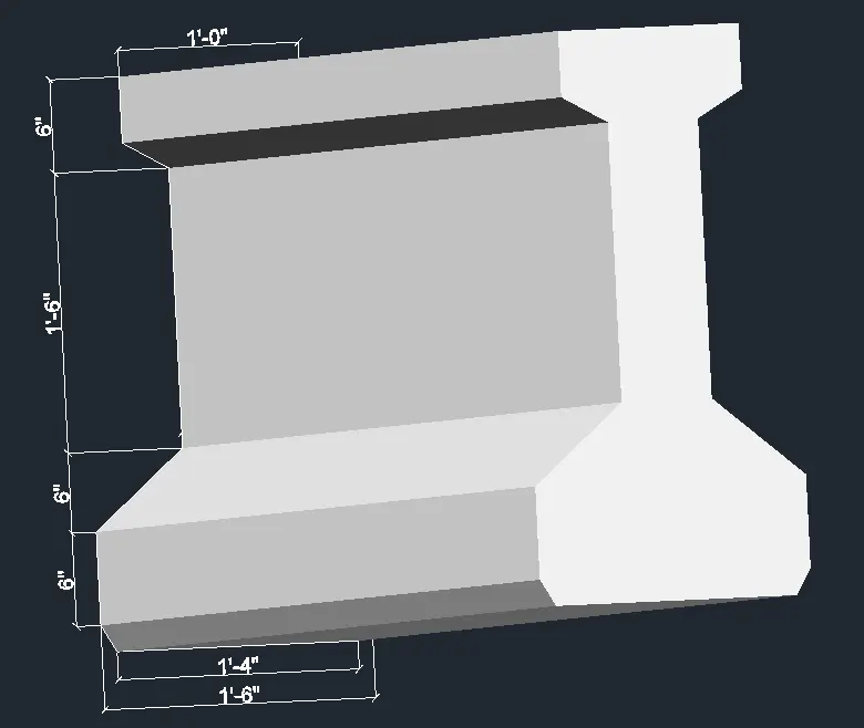
To create a 3D View of the AASTHO type girder using the various commands in Auto CAD.
PROCEDURE:
- To create a new sheet from application of Auto CAD.
- Go to the setting and to change the view of the page from Drafting to 3D modeling.
- Type UN to set the units of current format of measure.( feet and inches).
- Type LIMITS to set the maximum dimension limits on the particular page.
- First we take the top view of the page.
- To take L to create a line to draw the I section using given dimention.
- Then using 3D routate to rotate the object.
- Type REGION to converts objects.
- Type EXTRUDE to create a surface or solid of a 2D surface or a 3D curve.
- The extruded length of the section Girder is 10 feet.
- Then we have to change the view of 2D Wire, Shaded, Conceptional,,etc.
RESULTS:
The diagram of 3D type of AASTHO girder type is drawn as per dimensions using the software of Auto CAD.
DIAGRAM:
AIM:
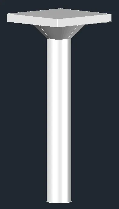
To create a 3D Model of a drop column with panel using the various commands in Auto CAD.
PROCEDURE:
- To create a new sheet from application of Auto CAD.
- Go to the setting and to change the view of the page from Drafting to 3D modeling.
- Type UN to set the units of current format of measure.( feet and inches).
- Type LIMITS to set the maximum dimension limits on the particular page.
- First we take the top view of the page.
- Type REC to create a rectangle with a given dimensions.
- And then we take to a 3D custom view.
- To choose the Top view of page.
- The rectangular size is 4’6”.
- Type C to create a circle options.
- The column cap height id 1 feet.
- The column head thickness is 6 inch,
- The height of the column is 10 feet.
- Extrude and Revalue the object using to create.
RESULTS:
The diagram of 3D model of a column with drop panel is drawn as per dimensions using the software of Auto CAD.
DIAGRAM:
AIM:
To create a 3D model of a wall using the various commands in Auto CAD.
PROCEDURE:
- To create a new sheet from application of Auto CAD.
- Go to the setting and to change the view of the page from Drafting to 3D modeling.
- Type UN to set the units of current format of measure.( feet and inches).
- Type LIMITS to set the maximum dimension limits on the particular page.
- First we take the top view of the page.
- To create the rectange 10 x 10 feet and door open 3 x 7 feet.
- Then top of the portion create using line and object.
- Both of the object to be 3d routate using to routate.
- Using Region to apply the object.
- Then extrude the object 9" wall thickness of the object.
RESULTS:
The diagram of 3D model of a wall is drawn as per dimensions using the software of Auto CAD.
DIAGRAM: