Creating 3D Isometric view of various structural elements in AutoCAD
Project-I
AIM:
To Create a 3D Isometric View of the building with plan and elevation using 3d Moduling in AutoCAD.
COMMANDS USED:
- Line command
- Rectangle command
- UCS command
- Dimlinear command
- Region command
- Extrude command
- Substract command
- Box command
- Units command
- Dimstyle command
- 3Dface command
- 3Dorbit command
- Hide command
- Explode command
- Move command
- Copy command
- Dist command
- Solidedit command
- Union command
- Boundary command
- 3Dmirror command
- 3Drotate command
- Erase command
PROCEDURE:
- First we have to open the autocad and the set the units and maximum limit and minimum limit on the screen and to change the workspace 3d modelling.
- Then first have to draw the plan of rectangle using the rectangle command dimention of 10'-9" and 10'-9".
- Then adding wall thickness of 9" view of both side wall.
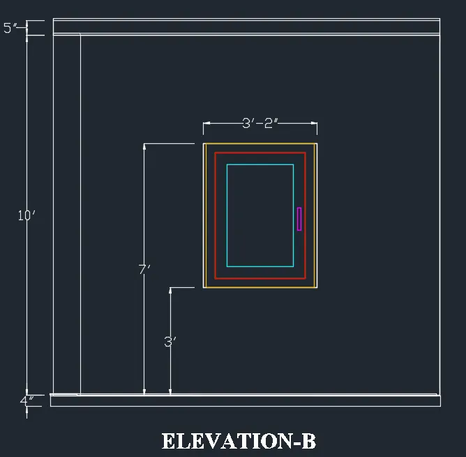
- To draw the window marking in the center of the wall window of 3'-3" and 3'-0" and draw the floor area using rectangle.
- And give the dimention of the wall and window distences.
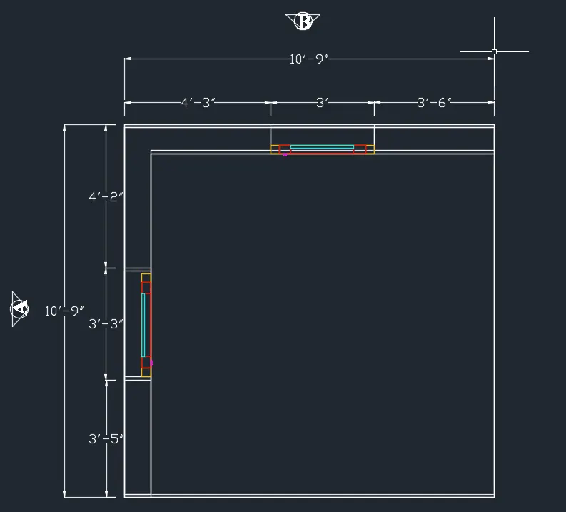
- Then to make region on wall for extrude the height of 10'-0" and window sill be draw the rectange and make region and extrude 3'-0" height and above lintel leavel be to extrude.
- To draw the window on top view and using 3d-rotate to change the plain extrude one by one of frame and door frame and glass using subract command and to apply the layyer properties colour.
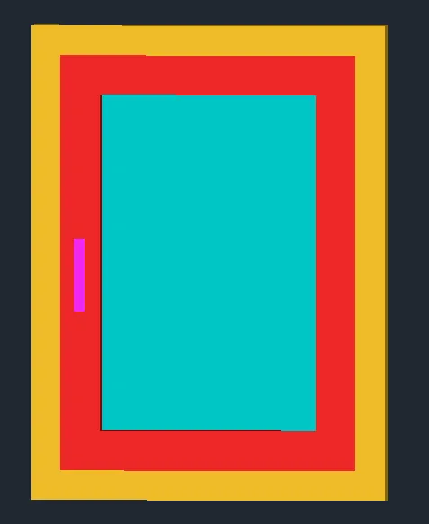
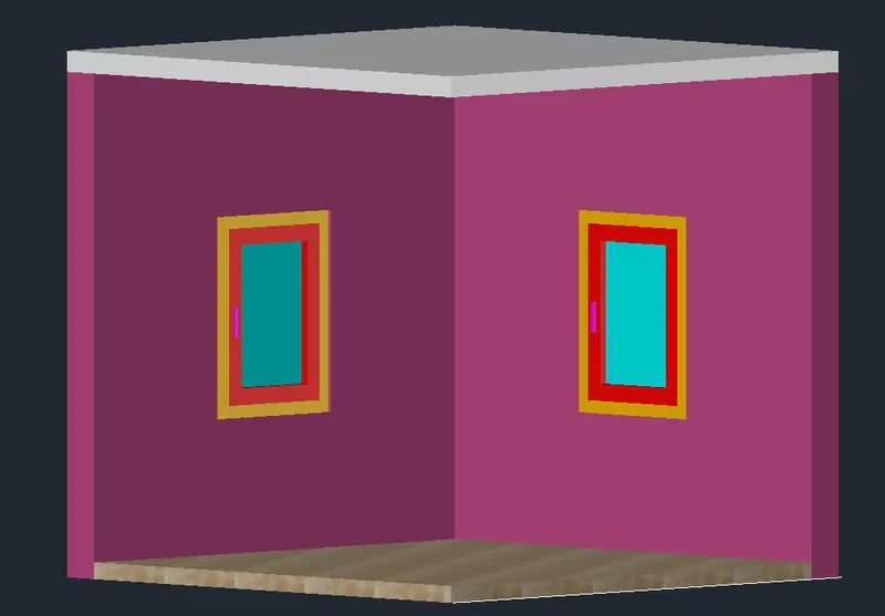
- Then to place the window on the extrude wall of elevation-a amd elevation-b.
- To apply the layer properties colour on the walls and material using apply the floor tiles.
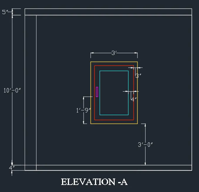
- Then do marking the elevation dimention of the A-B
RESULT:
The 3D isometric building with plan view and elevation view are draw successfully using AutoCAD.
Project-II
AIM:
To Create the 3D View of the Building Facade as given in the plan and elevation and need to create the window using the given dimensions using AutoCAD.
COMMANDS USED:
- Line command
- Rectangle command
- UCS command
- Dimlinear command
- Region command
- Extrude command
- Substract command
- Box command
- Units command
- Dimstyle command
- 3Dface command
- 3Dorbit command
- Hide command
- Explode command
- Move command
- Copy command
- Dist command
- Solidedit command
- Union command
- Boundary command
- 3Dmirror command
- 3Drotate command
- Erase command
- Plan command
PROCEDURE:
- First we have to open the autocad and the set the units and maximum limit and minimum limit on the screen and to change the workspace 3d modelling.
- To draw the plan view of draw the rectangle 10'9" x 6'-9".
- Offset to the wall thickness 9" in the inner side of the wall and to draw the window on the front portion to be crateed.
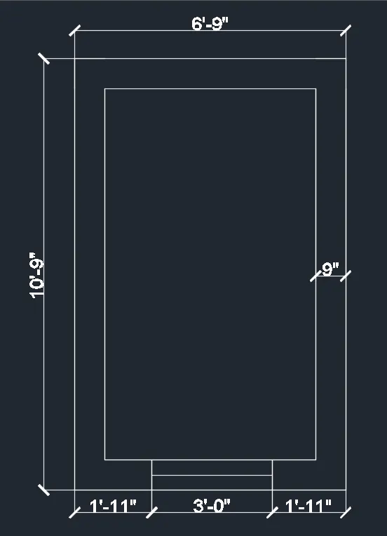
- Then to make region on wall for extrude the height of 10'-0" and window sill be draw the rectange and make region and extrude 4'-6" height and above lintel leavel be to extrude.
- To draw the window on top view and using 3d-rotate to change the plain extrude one by one of frame and door frame and glass using subract command and to apply the layyer properties colour.
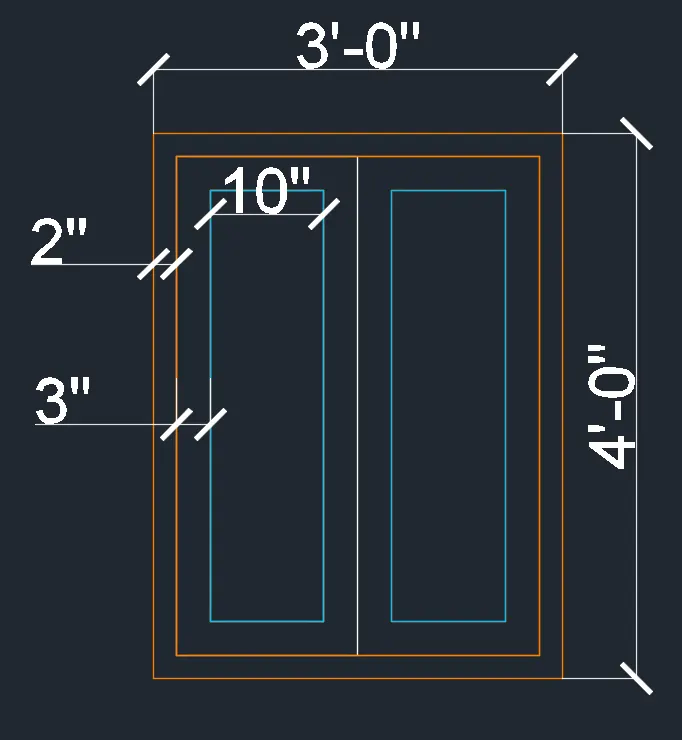
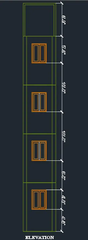
- Then to draw the elevation using array command to give the column value 1 and row value 1 level value of 4 in between distance for the 10feet to each floor to given.
- To change the view of draw on rectangle by 4" x 9" to region and extrude height of 6'-9".
- To apply the layer properties of the front elevation objects.
RESULT:
The 3D View of the Building Facade as given in the plan and elevation and window are drawn successfully using AutoCAD.
Project-III
AIM:
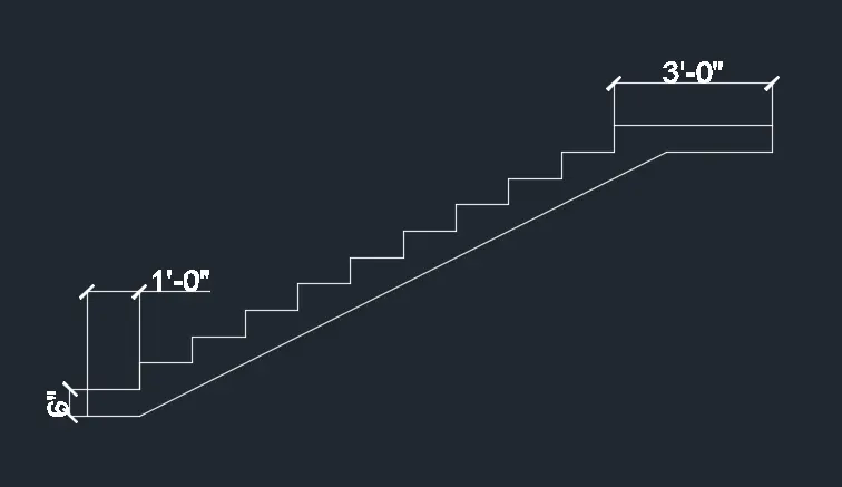
To create the ismoteric 3d view of a stair with railing as shown in the plan and elevation using AutoCAD.
COMMANDS USED:
- Line command
- Rectangle command
- UCS command
- Dimlinear command
- Region command
- Extrude command
- Substract command
- Box command
- Units command
- Dimstyle command
- 3Dface command
- 3Dorbit command
- Hide command
- Explode command
- Move command
- Copy command
- Dist command
- Solidedit command
- Union command
- Boundary command
- 3Dmirror command
- 3Drotate command
- Erase command
- Plan command
PROCEDURE:
- First we have to open the autocad and the set the units and maximum limit and minimum limit on the screen and to change the workspace 3d modelling.
- Using poly-line to draw the riser&thread of 6"-12" respectivlly draw on top view landing of 3 feet and weist slab be drawn.
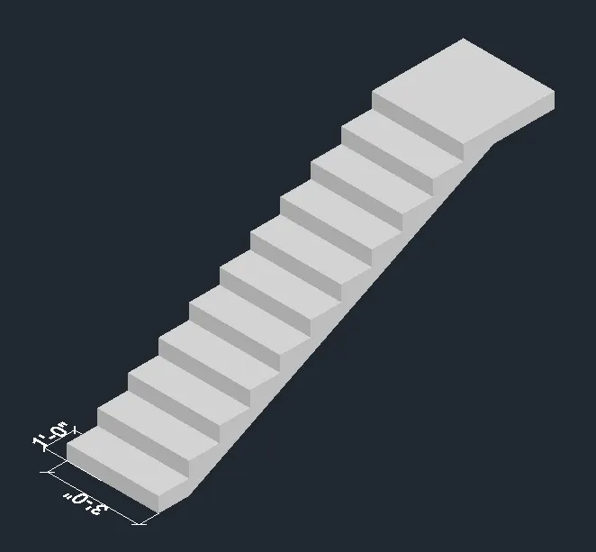
- Using 3d rotate to change the x direction into 90 degree.
- Rgion to make the object in boundary line then to extrude the staircase width of 3 feet.
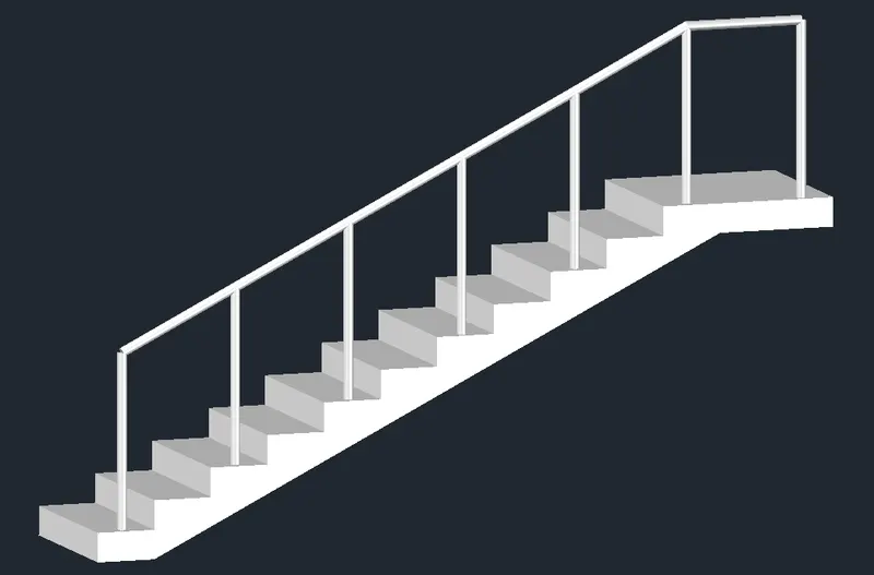
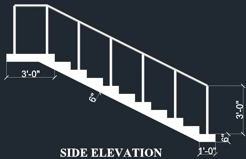
- To draw the handrail of bulster using circle command to draw the 1" dia on thread on center and to make region it and extrude the bulster height of 3 feet.
- Then the bulster to copy to the stair thread then using polyline to connect the edges of the bulster center to connected the all and reference handrail circle is draw for sweep.
- Sweep command using to handrail drawn entire bulsters.
RESULT:
The ismoteric 3d view of a stair with railing plan and elevation drawn successfully using AutoCAD.
Project-IV
AIM:
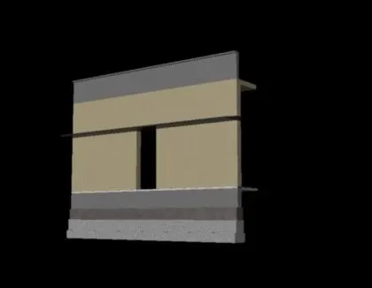
To draw the 3D view of a Wall with spread footing as shown in the plan and elevation.
COMMANDS USED:
- Line command
- Rectangle command
- UCS command
- Dimlinear command
- Region command
- Extrude command
- Substract command
- Box command
- Units command
- Dimstyle command
- 3Dface command
- 3Dorbit command
- Hide command
- Explode command
- Move command
- Copy command
- Dist command
- Solidedit command
- Union command
- Boundary command
- 3Dmirror command
- 3Drotate command
- Erase command
- Plan command
PROCEDURE:
- First we have to open the autocad and the set the units and maximum limit and minimum limit on the screen and to change the workspace 3d modelling.
- To draw the section view of steped footing using given dimentions.
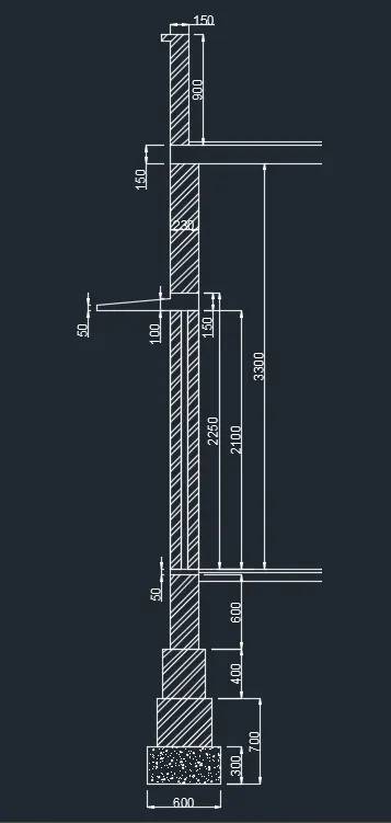
- To hatched the seprated object to highlight the object and copy to the make it region on each element of object.
- Then Using 3drotate to change the x direction into 90degree.
- Using Extrude to 7500mm in the wall length.
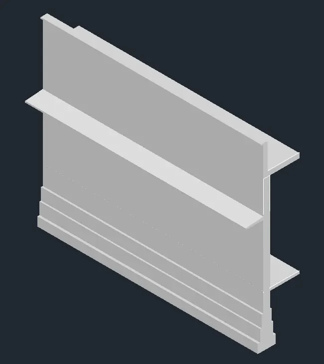
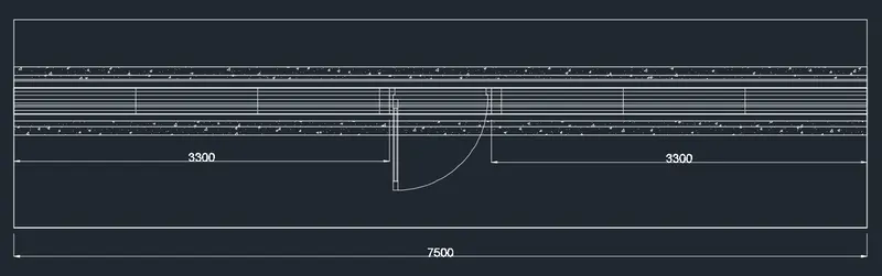
- To apply the material properties of the object like concrete,wall painting,highlight the elements.
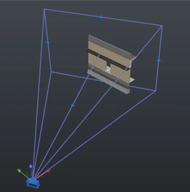
- To set the camera for rendering the object height of cam 5.25' feet.
RESULT:
the 3D view of a Wall with spread footing plan and elevation drawn successfully using AutoCAD.